
Installation Guide

Installing the Data Module, Hardware Key, and Remote Maintenance Line
Chapter 3
Installing the Data Module 3-7
Power Up 3
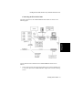
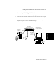
When you first apply power to the 7400B/7400B Plus, the unit carries out a self-test
to determine that it is in working order. The progression of the self-test is indicated
by the sequential left-to-right lighting of the front-panel LEDs. When the self-test
completes, the LEDs labeled POWER/TEST and TR will remain lit and all other
LEDs will go out.
If the unit is not configured correctly, the POWER/TEST and DATA LEDs will
flash.
See the 7400B/7400B Plus Data Module User Guide to resolve configuration
problems.
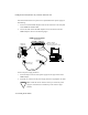
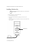
Installing an 8400B Plus Data Module with a Telephone 3
This section describes the equipment you need to install an 8400B Plus Data
Module with a telephone and the steps you must follow to prepare it to operate. The
8400B Plus comes with the default option set to be used with a telephone.
To install an 8400B Plus Data Module, you will need the following:
• One 8400B Plus Data Module.
• One EIA-232 cable.
• One D8W cord.
• If Data Module power is not available through the phone jack, you will also
need one 8400B Plus Data Module power supply.
• If a KS-22911 power supply is used, you will need a 400B2 adapter.
• If an MSP-1 power supply is required, you will also need an extra D8W cord.
• If the communications port on the PC has nine pins, you will need an M25/F9
adapter.
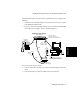
Selecting an EIA-232-D Cable 3
Select an EIA-232-D with a male connector at one end to connect to the Port 1
connector of the 8400B Plus, and a connector of the appropriate gender at the other
end to connect to the communications port of your PC.