
Installation Guide

Installing the Data Module, Hardware Key, and Remote Maintenance Line
3-10 Installing the Data Module
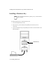
If the data module will receive power from a separate KS-22911 power supply, do
the following:
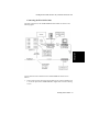
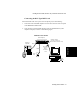
1. Insert one end of the D8W telephone cord into the connector on the rear panel
of the 8400B Plus labeled LINE.
2. Connect the other end of the D8W telephone cord to the lower socket of a
400B2 adapter as shown in the following figure.
.
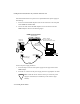
Connect the power supply as follows:
1. Insert the output connector of the power supply into the upper socket of the
400B2 adapter.
2. Insert the AC connector of the power supply unit into an appropriate AC outlet.
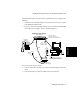
Caution
Make certain that the AC outlet to which you connect the power
supply is unswitched (not controlled by a wall switch or light
dimmer).
PHONE
LINE/
POWER
!
USE ONLY WITH COMMUNICATION
CIRCUIT POWER SO URCE
(use only with 25-pin
(Rear Endplate)
EIA-232-D
D8W
M9/F25 Adapter
8400B Plus Data Module
EIA-232-D Connector Cord)
(9-pin or 25-pin)
Connector Cord
Wall
D8W
D6AP
AC
Outlet
400B2
Adapter
KS-22911, L2
Jack
Power Supply
Telephone
(Optional)