Call Stacker Installation and Use Manual Issue 1, October 1999 © 1999 Bogen Communications, Inc. All rights reserved.
© 1999 Bogen Communications, Inc. All Rights Reserved. Printed in U.S.A. Notice Every effort was made to ensure that the information in this guide was complete and accurate at the time of printing. However, information is subject to change. FCC Statement (Part 15) - Radio Frequency Interference The Call Stacker generates and uses radio frequency energy and if not installed and used in strict accordance with the manufacturer's instructions, may cause interference to radio and television reception.
Contents 1. Overview1-1 Introduction Before You Start n n 2. Installation 2-1 Installation Steps n 3.
This page intentionally left blank.
Overview Contents Introduction 1-2 Before You Start 1-3 Overview 1-1
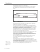
Introduction The Call Stacker is a microprocessor based audio recording and announcement system. The Call Stacker is used in conjunction with a paging system to provide buffered announcement play to the paging system. Figure 1-1. Call Stacker Unit The Call Stacker features 5 Input Station (recording) channels, a single Page Output channel and 3 minutes of recording time.
Before You Start Before installing your system, read and understand the safety instructions on page ii (inside front cover). Be sure you have all the necessary parts, tools, and test equipment, listed below. 1. Read important Safety Information on Page ii. 2. Check Shipping Container Contents. n Call Stacker Unit n Mounting Hardware (screws and brackets) n Power Cord n This Installation and Use Guide 3. Have Required Tools The following tools are required for the installation of the hardware and cabling.
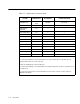
Table 1-1. Call Stacker Connectivity Chart.
Installation Contents Installation Steps 2-2 Installation 2-1
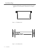
Installation Steps 1. Attach the reversible brackets to the Call Stacker using the 6-32 x 3/8" screws provided, then secure the Call Stacker to a back board or into an equipment rack. Figure 2-1. Wall Mounted Unit Figure 2-2.
2. Set the option switch on the Call Stacker (see Figure 3-1 on page 3-2) for the desired system configuration (refer to Table 2-1). NOTE: When the switch #7 is “OFF”, there will be no delay in time from when the paging system zone is accessed until the time when the message is sent. When the switch #7 in “ON”, there will be a 2 second delay from when the paging system/zone is accessed until the time when the message is sent.
Figure 2-3. Page Output Channel Connection of Call Stacker Figure 2-4. Connection to Lucent LUPCM Zone Paging System Figure 2-5.
4. Connect the detachable power supply cord between a 110/120 VAC outlet and the Call Stacker and verify the Power LED illuminates. 5. Turn the battery switch ON.
This page intentionally left blank.
Operation Contents Operation 3-2 ■ Controls and Indicators 3-2 ■ Recording Announcements 3-3 ■ Announcement Playback 3-4 Maintenance ■ Troubleshooting Specifications 3-5 3-5 3-5 Operation 3-1
Operation Controls and Indicators Figure 3-1. Rear Panel Detail Table 3-1. Rear Panel Description ITEM DESCRIPTION Power On LED Illuminates when power is supplied to the Call Stacker. Pause Override Control Input Enables/disables the Page Output channel. When a contact closure (a short) between the two terminals is detected, the Call Stacker terminates the outgoing announcement (if any), requeues it and disables the Page Output channel.
Recording Announcements Voice Prompts Enabled 1. Dial up the input station connected to the Call Stacker. The Call Stacker answers the trunk and responds “Enter zone code (Marque el codigo de la zona)”. Proceed to step 2.
Voice Prompts Disabled 1. Dial up the input station connected to the Call Stacker and wait for the Call Stacker to answer the trunk and respond with a high tone. Proceed to step 2. NOTE: If the number of digits in the paging zone is set to 0 (see Table 2-1), skip step 2 and proceed to step 3. 2. Enter a DTMF tone sequence using the telephone keypad to select a paging zone. Once the required number of DTMF digits (see table 2-1) are entered, the Call Stacker responds with a high tone. Proceed to step 3.
Maintenance Troubleshooting NOTE: The suggested reliable lifetime of the rechargeable battery used in the equipment is 36 months. To ensure the system has reliable battery backup, it is recommended the battery be replaced every 30 months. There are no serviceable parts in the Call Stacker: If the Call Stacker does not operate during a power failure: n Verify the battery switch is turned ON. n Verify the battery is fully charged. Allow 48 hours to fully charge.