Multi-Zone Microphone Installation and Use Manual Issue 1, October 1999 © 1999 Bogen Communications, Inc. All rights reserved.
© 1999 Bogen Communications, Inc. All Rights Reserved. Printed in U.S.A. Notice Every effort was made to ensure that the information in this guide was complete and accurate at the time of printing. However, information is subject to change. Important Safety Information Always follow these basic safety precautions when installing and using the system: 1. Read and understand all instructions. 2. Follow all warnings and instructions marked on the product. 3.
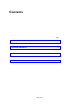
Contents Page DESCRIPTION ................................................................................................................................4 PACKAGE CONTENTS..............................................................................................................4 INSTALLATION & WIRING ....................................................................................................5 OPERATION ..........................................................................................
Description: Your Lucent Technologies' High Fidelity desk microphone provides high quality, low noise, multi-zone paging capability to all existing Lucent paging products. The multi-zone microphone provides a DTMF pad for unlimited zone access, or it can be switched to a dedicated single zone. A cardioid electret element suppresses background noise, and is housed on the end of a flexible tube. You can page through a momentary push-button for short pages, or make a long page with a lock-on button.
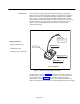
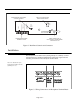
SCREWDRIVER-ACCESSIBLE VOLUME CONTROL SWITCH FOR DEDICATED SINGLE ZONE PAGING Status Line Output + Normally Open Contacts Single Zone Page - + On Mic Level Control Off - COMPRESSION SCREW TERMINAL BLOCK CABLE CONNECTED TO WALL SOCKET TRANSFORMER PROVIDES 12 VAC Figure 2. Back Panel Controls and Connectors Installation The microphone has rubber feet for placing directly on a desktop. Connect the transformer to a standard 120VAC 60 Hz wall socket.
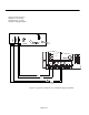
Figure 4 shows the wiring diagram for connecting microphones to a Lucent Telephone Paging Amplifier. MIC VOLUME TEL VOLUME ALC TEL CONTROLS COM MIC BRIDGING MUSIC IN APHEX MIC BAL + GND TEL BAL T R CONTACT RING TEL RING Figure 4.
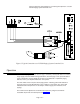
Figure 5 shows the wiring diagram for connecting microphones to a Lucent LUPCM Paging System Controller Unit. I Figure 5. Typical Connections to a LUPCM Paging System Controller Unit Operation To make a short page, press and hold the larger, momentary contact push-button. To make a longer page, press the smaller locking push-button; when the page is over, press this button again to deactivate.