Telephone Paging Amplifier 250-Watt Model Installation and Use Manual Issue 2, January 2000 © 1999 Bogen Communications, Inc. All rights reserved.
© 1999 Bogen Communications, Inc. All Rights Reserved. Printed in Korea. Notice Every effort was made to ensure that the information in this guide was complete and accurate at the time of printing. However, information is subject to change. Important Safety Information Always follow these basic safety precautions when installing and using the unit: 1. Read and understand all instructions. 2. Follow all warnings and instructions marked on the product. 3.
Contents Page INTRODUCTION ..........................................................................................................................4 PACKAGE CONTENTS..............................................................................................................4 INSTALLATION..............................................................................................................................5 Mounting ...................................................................................
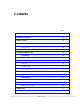
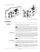
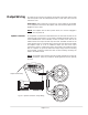
Telephone Paging Amplifier POWER PEAK LEVEL APHEX REF TREBLE REF BASS RINGER VOLUME MUSIC MUTE MUSIC VOLUME REF 250 WATT AMPLIFIER MIC VOLUME REF TEL VOLUME LUCENT TECHNOLOGIES REF ALC BRIDGING MUSIC IN TEL CONTROLS COM MIC MIC BAL + GND TEL BAL T CONTACT RING R T TEL RING R 70V 25V COM GND Figure 1: Telephone Paging Amplifier Introduction This document describes the Lucent 250-watt Telephone Paging Amplifier.
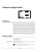
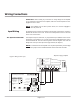
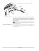
Figure 2: Wall Mounting the Amplifier SCREW #8 x 5/8" (M4 x 16 mm) WITH TEFRON WASHER 1/8 x 5/16 (3 x 8 MM) TYP 4 PCS WER L PO VE AK LE PE HEX AP LE EB TR SS WER BA L PO VE .... LE AK PE ER RING X HE AP LE SIC EB SS ME MUS .... ME .... .... VO .... MIC .... . .... .... .... . .... .... ME VO ME L VO .... ME LU VO .... .... LU E MUT SIC MU .... .... LU .... LU ER RING MUS .... TE LU VO IC BA IC ME LU VO MU MU TR TE .... .... ...
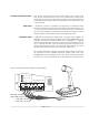
Wiring Connections IMPORTANT: Before making any connections or wiring changes to the amplifier or any equipment connected to the amplifier, make sure that the amplifier is NOT plugged into an AC outlet. NOTE: The amplifier does not have a power switch, so it must be unplugged in order to turn the power off. Input Wiring All signal input and control wiring is made to the terminal strip and RCA connectors beneath the left side access cover.
Tel Input to Universal Coupler After properly connecting your Universal Coupler (909) to your auxiliary trunk port, set your switches as follows: C1/C2 to C2; Rocker Switch 3 closed; and all others open. Coming out of the J2 Jack of the Coupler, connect the blue/white pair to the amplifier Tip and Ring. Connect the brown/white pair to Tel and Com on the control terminals. Music Input A single RCA connector is provided for the connection of a background music source.
Night Ringer Connection Either a standard telephone (analog) ring signal (90 - 105 V AC, 20 - 30 Hz) or an external contact closure activates the night ringer function of the amplifier. To activate the night ringer using standard telephone (analog) ring, connect the analog station's tip lead to the TEL RING "T" terminal and connect the ring lead to the "R" terminal. If using an external contact closure, connect the closure pair across the CONTACT RING terminals (not polarized).
Output Wiring All output wiring connections are made to the terminal strip located under the right side access panel. Loosen the 2 Phillips-head screws on each side of the cover and remove the cover. IMPORTANT: Before making any connections or wiring changes to the amplifier or any equipment connected to the amplifier, make sure that the amplifier is NOT plugged into an AC outlet. NOTE: The amplifier does not have a power switch, so it must be unplugged in order to turn the power off.
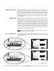
Figure 8 : LUWMT1A Connection to RCA Jack on Amplifier RCA Jack BLE . .... A EPT CC G A ... .. IRIN 2W SS ... .. CLA . .... T-..A WM LUWMT1A Amplifier LUWMT1A Connector An RCA jack is provided near the output terminal strip for connection to an LUWMT1A impedance matching transformer (Com Code 405891680). A 600-ohm, telephone level output signal can be obtained by plugging the RCA connector of the LUWMT1A into this jack and taking the output signal off of the LUWMT1A screw terminals (see Figure 8).
Operation IMPORTANT: Before plugging the amplifier into an AC outlet, turn all volume controls to their full counterclockwise positions and all other controls to their reference position or to mid rotation. Indicators POWER IND The POWER IND LED illuminates whenever AC power is applied to the amplifier (there is no power switch on the amplifier). PEAK LEVEL The PEAK LEVEL LED illuminates whenever the speaker output signal level approaches its maximum level.
MUSIC VOLUME This control adjusts the level of the background music output. No reference level setting position is provided. The background music level should be set to an acceptable level without overdriving the system. When adjusting this level, the PEAK LEVEL indicator should be observed to ensure that the amplifier signal is not distorted. MUSIC MUTE This control adjusts the level of the background music heard during a paging announcement. No reference level setting position is provided.