Universal Paging Access Module Installation and Use Manual Issue 1, October 1999 © 1999 Bogen Communications, Inc. All rights reserved.
© 1999 Bogen Communications, Inc. All Rights Reserved. Printed in U.S.A. Notice Every effort was made to ensure that the information in this guide was complete and accurate at the time of printing. However, information is subject to change. Federal Communications Commission (FCC) Statement (Part 68) This equipment is component registered with the Federal Communications Commission (FCC) in accordance with Part 68 of its rules.
Contents 1. Product Identification ..................................................................................5 UPAM Universal Paging Access Module ............................................................................5 Overview................................................................................................................................5 Features ..................................................................................................................................
This page left blank intentionally.
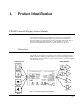
1. Product Identification UPAM Universal Paging Access Module The UPAM Universal Paging Access Module is designed to provide telephone access to most commonly available paging systems. It works with PBX loop, ground start trunk ports, and station ports and is compatible with the full range of currently available telephone equipment, i.e., PBX, stand-alone 1A2-Key, Electronic Key, Hybrid Electronic Key, or CO and Centrex.
Features 24V or 48V Operation (Trunk Port Operation) MODE switches let you select 24V (not included) or 48V (included) power supply. A 48-volt power supply is included to provide 48-volt trunk port operation. Pre-announce and Confirmation Tones A pre-announce tone (heard at the telephone and the loudspeakers) or confirmation tone (heard only at the telephone) can be selected with MODE switches. (One of these modes must be selected for the unit to operate properly.
2. Connection to the Telephone System General Instructions Overview Required Tools Select Location and Physical Installation This section contains installation procedures for connection to the telephone system. You should first follow the General Instructions and then refer to the Specific Instructions for the type of telephone switch to be connected (loop or ground start trunk port, station port, or page port). Refer to Section 3 for connections to the paging system.
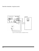
General Instructions (cont’d) MODE Switches (on front of unit) A set of 5 MODE switches (S1 through S5, see Figure 1 on page 5) is included to set the power supply voltage, confirmation or pre-announce tone, and VOX operation. These switches are accessible through an opening in the front cover and can be moved with a pointed tool, such as the tip of a ballpoint pen. Set the switches as described in the Specific Instructions (pages 9 - 18).
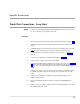
Specific Instructions Trunk Port Connections - Loop Start NOTE: Controls for VOX DELAY, PAGING TIME, MODE Switch S5 and AUX switches S1, S2, S3, and S5 are not operable in this mode. Procedure 1. Mount and ground the UPAM as described in the General Instructions (pages 7-8). 2. Set MODE switches S1 and S2 to OFF position for use with the 48-volt power supply. 3. Set MODE switches S3 and S4 for Pre-announce or Confirmation tone (as desired).
Trunk Port Connections - Loop Start (cont'd) Figure 2: Trunk Port Connection: Loop Start Trunk Port [10]
Specific Instructions Trunk Port Connections - Ground Start NOTE: Controls for VOX DELAY, PAGING TIME, MODE Switch S5 and AUX switches S1, S2, S3, and S5 are not operable in this mode. Procedure 1. Mount and ground the UPAM as described in General Instructions (pages 7 - 8). 2. Set MODE switches S1 and S2 to OFF position for use with the 48-volt power supply (or ON position if a 24-volt supply is used). 3. Set MODE switch S3 to ON position and S4 to OFF position.
Trunk Port Connections - Ground Start (cont'd) 9. NOTE: Connect UPAM +24/48V terminal to PBX ground. Usually the AC GND terminal on the included 48-volt power supply can be used to provide this connection. 10. Connect power supply + and - terminals to +24V/48V and -24V/48V terminals on UPAM, respectively. Plug the power supply into a grounded 110V AC wall outlet. 11. Call the system and adjust the volume of the page using the paging system's amplifier volume control. 12.
Specific Instructions Station Port / Centrex Connections Disconnect Methods IMPORTANT In station port operation, the UPAM provides CPC (calling-party-controlled) [loop current interruption] disconnect, default timer disconnect, or optional voiceoperated (VOX) disconnect. The calling-party-controlled disconnect recognizes a line-issued disconnect signal and immediately disengages the UPAM from the line (this feature cannot be adjusted or inhibited).
Station Port / Centrex Connections (cont’d) 5. Connect "Tip" of station port to T terminal of UPAM (see Figure 5). 6. Connect "Ring" of station port to R terminal of UPAM. 7. Connect PT and PR terminals on UPAM to the paging system, as shown in Section 3. Connect the N.O. and COM terminals to the control pair of the amplifier, if required. Also, connect any background music source to the BGM IN jack on the UPAM. 8.
Station Port/Centrex Connections (cont'd) Important Centrex Settings Some phone systems (in particular, Centrex-type systems) may produce openswitch-intervals (OSIs) when the UPAM first answers the line. OSIs are short breaks in loop current resulting when the central office switches equipment on and off the line. The UPAM may misinterpret these OSIs as disconnect signals.
Station Port/Centrex Connections (cont'd) Inhibit Default Timer An option is available to inhibit the default timer. Do not inhibit the timer if AUX switches S4 and S5 are in the OFF position (outlined in Important Centrex Settings on page 15) and the VOX DELAY timer has been disabled (MODE switch S5 is OFF). This situation may cause the UPAM to remain off-hook indefinitely. Also, do not inhibit both the default and VOX timers unless the station line has CPC capability.
Specific Instructions Trunk Port Connections - Page Port NOTE: Controls for VOX DELAY, PAGING TIME, MODE Switch S5 and AUX switches S1, S2, S3, and S5 are not operable in this mode. Procedure 1. Mount and ground the UPAM as described in the General Instructions (pages 7 - 8). 2. Set MODE switches S1 and S2 to OFF position for use with the 48-volt power supply (or ON position if a 24-volt power supply is used). 3. Set MODE switches S3 and S4 for Pre-announce or Confirmation tone (as desired).
Trunk Port Connections - Page Port (cont'd) 7. Connect PT and PR terminals and contact closure on UPAM to the paging system, as shown in Section 3. Connect the N.O. and COM terminals to the control pair of the amplifier, if required. Also, connect any background music source to the BGM IN jack on the UPAM. 8. Connect power supply + and - terminals to the +24V/48V and -24V/48V terminals on UPAM, respectively. Plug the power supply into a grounded 110V AC wall outlet. 9.
3. Connection to the Paging System General Guidelines The UPAM is designed to connect to typical central-amplified and self-amplified paging and sound systems. Central-amplified systems generally use one amplifier to distribute the page audio to large numbers of speakers. Self-amplified systems generally rely on small amplifiers, built-in on each speaker or horn.
Connecting the UPAM to an Amplifier's Lo-Z/600-ohm Input (cont’d) 1. Make sure that the amplifier is turned off or unplugged. 2. Connect one side of the amplifier’s input to the UPAM PT terminal. 3 Connect the other side of the amplifier’s input to the UPAM PR terminal. 4. Connect any background music source to the BGM IN jack (RCA-type) on UPAM. 5. Connect the N.O. and COM terminals to the control pair of the amplifier, if required. CAUTION 6.
Connecting the UPAM to an Amplifier’s Lo-Z/600-ohm Input (cont'd) Figure 7.
Typical Installation: Connecting the UPAM to an Amplifier’s Hi-Z AUX Input You can connect the UPAM to an amplifier's Hi-Z input by using the LUWMT1A transformer (included) to match the UPAM output to the amplifier input (see Figure 8). Make sure the LUWMT1A is set for line level operation (see the instructions included with the transformer for connection details). [22] 1. Make sure that the amplifier is turned off or unplugged. 2.
Connecting the UPAM to an Amplifier's Hi-Z AUX Input (cont'd) Figure 8.
Typical Installation: Connecting the UPAM to an Amplifier’s MIC Input Due to the higher sensitivity of Hi-Z microphone inputs, they should be used only as a last resort. Both Hi-Z and Lo-Z inputs can be accomodated. The Lo-Z microphone connection is the more desirable of the two because it is less susceptible to noise pickup. The UPAM connects to the MIC input using the LUWMT1A transformer (see Figure 8). This transformer includes a microphone input modification to provide the proper attenuation. [24] 1.
Connecting the UPAM to an Amplifier's MIC Input (cont'd) Figure 9.
Typical Installation: Connecting the UPAM to a Self-Amplified Paging System Connection to a self-amplified system usually consists of connecting the UPAM output to the line feeding the system's individual amplifiers. In some cases, connection can be made to a small buffer amplifier, which is used in some systems to provide an adequate signal level for multiple speakers. [26] 1. Most self-amplified systems operate at low voltages and do not present a shock hazard.
Connecting the UPAM to a Self-amplified Paging System (cont'd) Figure 10.
4. Troubleshooting Functional Test Guide Use the following chart to verify proper operation after installation. To start the test, pick up a telephone and call the UPAM. Does the UPAM activate? The UPAM is activated if it returns a tone over the telephone, the external contacts close, and relays inside the unit click when paging is accessed. NO YES Check List 1. Double check for correct wiring to voice switch. 2. Make sure wires are making good contact. 3.
Procedure A 1. Disconnect the UPAM from the telephone equipment. 2. Confirm that the power supply is properly connected and that the MODE switches are in the correct positions (make sure MODE switches S3 and S4 are not in the same position). Note: If in station mode, connect the power supply. 3. Connect a test set to T & R terminals on UPAM (test set should be on hook). See Figure 11. 4. Take test set off hook.
Troubleshooting (cont'd) Procedure B 1. Disconnect the UPAM from the paging system. 2. Connect a test set to PT & PR terminals on UPAM (see Figure 12). 3. Place the test set in the monitor position. 4. Make a page from a telephone system phone. Listen to the test set. Audio should be comfortably loud (approximately telephone level) and not distorted. If audio is loud and clear, the paging interface is working correctly. The problem must be in the paging system.