
User's Manual
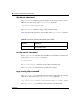
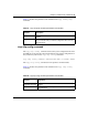
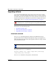
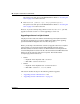
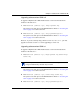
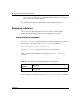
Table Of Contents
- Reference for the Business Policy Switch 2000 Command Line Interface
- Contents
- Figures
- Tables
- Preface
- Chapter 1: CLI Basics
- Stacking compatibility
- Software version 2.0 compatibility with BayStack 450 switches
- New features
- CLI command modes
- Port numbering
- IP notation
- Accessing the CLI
- Setting the CLI password
- Getting help
- Basic navigation
- Managing basic system information
- Managing MAC address forwarding database table
- Displaying and setting stack operational mode
- Chapter 2: General CLI commands
- Setting the terminal
- Pinging
- Automatically loading configuration file
- Assigning and clearing IP addresses
- Assigning and clearing IP addresses for specific units
- Setting Telnet access
- Setting server for Web-based management
- Setting boot parameters
- Setting TFTP parameters
- Upgrading software
- Displaying interfaces
- Setting SNMP parameters
- Setting the system event log
- Displaying port statistics
- Enabling or disabling a port
- Naming ports
- Setting port speed
- Enabling Autopology
- Enabling flow control
- Enabling rate-limiting
- Chapter 3: Security
- Using the IP manager list
- Using MAC address security
- show mac-security command
- show mac-security mac-da-filter command
- mac-security command
- mac-security mac-address-table address command
- mac-security security-list command
- no mac-security command
- no mac-security mac-address-table command
- no mac-security security-list command
- mac-security command for specific ports
- mac-security mac-da-filter command
- Using EAPOL-based security
- Using RADIUS authentication
- Chapter 4: Spanning Tree, MLT, and Port-Mirroring
- Using spanning tree
- show spanning-tree command
- spanning-tree stp create command by STG
- spanning-tree stp delete command by STG
- spanning-tree stp enable command by STG
- spanning-tree stp disable command by STG
- spanning-tree command by STG
- default spanning-tree command by STG
- spanning-tree add-vlan command
- spanning-tree remove-vlan command
- spanning-tree command by port
- default spanning-tree command by port
- no spanning-tree command by port
- Using MLT
- Using port-mirroring
- Using spanning tree
- Chapter 5: VLANs and IGMP
- Increased VLAN support
- Configuring and displaying VLANs
- show vlan interface info command
- show vlan interface vids command
- vlan mgmt command
- default vlan mgmt command
- vlan create command
- vlan delete command
- no vlan command
- vlan name command
- auto-pvid command
- no auto-pvid command
- vlan ports command
- vlan members command
- show vlan mac-address command
- vlan mac-address command
- no vlan mac-address command
- Displaying multicast membership
- Using IGMP snooping
- Chapter 6: Policy-enabled networks and QoS
- Displaying QoS parameters
- Resetting
- Configuring COPS
- Configuring QoS interface groups
- Configuring DSCP and 802.1p and queue associations
- Configuring QoS filters and filter groups
- Configuring QoS actions
- Configuring QoS meters
- Configuring QoS shapers
- Gathering QoS statistics
- Configuring QoS policies
- Reordering packets
- Appendix A: Command List
- Index

Chapter 2 General CLI commands 85
Reference for the Business Policy Switch 2000 Command Line Interface
Upgrading software images
You follow a different procedure depending if you are using a Pure BPS 2000
stack or a Hybrid stack.
The stacking software compatibility requirements are as follows:
• Pure BPS 2000 stack—All units must be running the same software version.
• Pure BayStack 450 stack—All units must be running the same software
version.
• Hybrid stack:
— All BPS 2000 units must be running the same software version.
— All BayStack 410 units must be running the same software version.
— All BayStack 450 units must be running the same software version.
— All software versions must have the identical ISVN.
This section discusses the following topics:
• “Upgrading software in a Pure BPS 2000 stack,” next
• “Upgrading software in a Hybrid stack” on page 86
Upgrading software in a Pure BPS 2000 stack
To download, or upgrade, software in a Pure BPS 2000 stack:
1 Enter
download [address <ip>] image bps2000.img.
3 The switch programs the new
software image into the flash
memory.
100 Mb/s port status LEDs (ports 1 to 8 only): The LEDs begin to
turn on in succession beginning with port 1, which indicates that the
new software image is being programmed into the switch’s flash
memory. When LEDs 1 to 8 are all on, the new software image has
been programmed successfully into the switch’s flash memory.
4 The switch resets automatically. After the reset completes, the new software image initiates the
switch self-test, which comprises various diagnostic routines and
subtests.
The LEDs display various patterns to indicate that the subtests are in
progress.
Table 30 LED Indications during the software download process (continued)
Phase Description LED Indications