
User's Manual


Chapter 1 Device Manager basics 39
Reference for the Business Policy Switch 2000 Management Software Operations
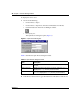
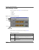
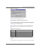
Figure 7 MDA dialog box
Table 6 describes the MDA dialog box fields.
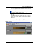
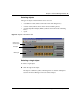
Media dependent adapters and port conventions
The conventions on the graphical representation of the switch are different from
the actual switch. This section explains these conventions and how information is
visually displayed on the MDAs and ports.
Table 6 describes the colors in the graphical representation of the MDA and its
ports. The ports on the chassis representation are color-coded to provide port
status.
A blinking LED on an MDA is not indicated in the graphical representation of the
switch.
For a full description of switch LEDs, refer to the respective switch user manuals.
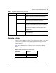
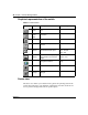
Table 6 MDA and MDA port colors
Color Description
Green The module/port is operating.
Red The module/port is present, but not operating.
Dark blue Port is being tested.
Dark red Port has been manually disabled.
Orange Port has no link.