Part No. 209570-C November 2001 4401 Great America Parkway Santa Clara, CA 95054 Using Web-based Management for the Business Policy Switch 2000 Software Version 2.
Copyright © 2001 Nortel Networks All rights reserved. November 2001. The information in this document is subject to change without notice. The statements, configurations, technical data, and recommendations in this document are believed to be accurate and reliable, but are presented without express or implied warranty. Users must take full responsibility for their applications of any products specified in this document. The information in this document is proprietary to Nortel Networks NA Inc.
USA requirements only Federal Communications Commission (FCC) Compliance Notice: Radio Frequency Notice Note: This equipment has been tested and found to comply with the limits for a Class A digital device, pursuant to Part 15 of the FCC rules. These limits are designed to provide reasonable protection against harmful interference when the equipment is operated in a commercial environment. This equipment generates, uses, and can radiate radio frequency energy.
Japan/Nippon requirements only Voluntary Control Council for Interference (VCCI) statement Taiwan requirements Bureau of Standards, Metrology and Inspection (BSMI) Statement Canada requirements only Canadian Department of Communications Radio Interference Regulations This digital apparatus (Business Policy Switch 2000) does not exceed the Class A limits for radio-noise emissions from digital apparatus as set out in the Radio Interference Regulations of the Canadian Department of Communications.
rights other than those granted to you under this License Agreement. You are responsible for the selection of the Software and for the installation of, use of, and results obtained from the Software. 1. Licensed Use of Software. Nortel Networks grants Customer a nonexclusive license to use a copy of the Software on only one machine at any one time or to the extent of the activation or authorized usage level, whichever is applicable.
e) The terms and conditions of this License Agreement form the complete and exclusive agreement between Customer and Nortel Networks. f) This License Agreement is governed by the laws of the country in which Customer acquires the Software. If the Software is acquired in the United States, then this License Agreement is governed by the laws of the state of New York.
Contents Preface . . . . . . . . . . . . . . . . . . . . . . . . . . . . . . . . . . . . . . . . . . . . . . . . . . . . . . 25 Before you begin . . . . . . . . . . . . . . . . . . . . . . . . . . . . . . . . . . . . . . . . . . . . . . . . . . . . . 25 Text conventions . . . . . . . . . . . . . . . . . . . . . . . . . . . . . . . . . . . . . . . . . . . . . . . . . . . . . 26 Related publications . . . . . . . . . . . . . . . . . . . . . . . . . . . . . . . . . . . . . . . . . . . . . . . . . . .
Contents Resetting the BPS 2000 to system defaults . . . . . . . . . . . . . . . . . . . . . . . . . . . . . . . . . 50 Logging out of the management interface . . . . . . . . . . . . . . . . . . . . . . . . . . . . . . . . . . 51 Chapter 3 Viewing summary information . . . . . . . . . . . . . . . . . . . . . . . . . . . . . . . . . . . 53 Viewing stack information . . . . . . . . . . . . . . . . . . . . . . . . . . . . . . . . . . . . . . . . . . . . . . 53 Viewing summary switch information . . . . . .
Contents 9 Creating an SNMPv3 target address configuration . . . . . . . . . . . . . . . . . . . . . 85 Deleting an SNMPv3 target address configuration . . . . . . . . . . . . . . . . . . . . . 87 Configuring an SNMPv3 management target parameter . . . . . . . . . . . . . . . . . . . 87 Creating an SNMPv3 target parameter configuration . . . . . . . . . . . . . . . . . . . 87 Deleting an SNMPv3 target parameter configuration . . . . . . . . . . . . . . . . . . . 89 Configuring SNMP traps . . . . . . . . . .
Contents Creating an RMON fault threshold . . . . . . . . . . . . . . . . . . . . . . . . . . . . . . . . . . . 130 Deleting an RMON threshold configuration . . . . . . . . . . . . . . . . . . . . . . . . . . . . . 132 Viewing the RMON fault event log . . . . . . . . . . . . . . . . . . . . . . . . . . . . . . . . . . . . . . . 133 Viewing the system log . . . . . . . . . . . . . . . . . . . . . . . . . . . . . . . . . . . . . . . . . . . . . . . 134 Viewing RMON Ethernet statistics . . . . . . . . . . .
Contents 11 Protocol-based VLANs . . . . . . . . . . . . . . . . . . . . . . . . . . . . . . . . . . . . . . . . . . . . 172 MAC SA-based VLANs . . . . . . . . . . . . . . . . . . . . . . . . . . . . . . . . . . . . . . . . . . . . 172 Configuring VLANs . . . . . . . . . . . . . . . . . . . . . . . . . . . . . . . . . . . . . . . . . . . . . . . . . . . 173 Creating a port-based VLAN . . . . . . . . . . . . . . . . . . . . . . . . . . . . . . . . . . . . . . . . 175 Modifying a port-based VLAN . . . . . . .
Contents Configuring QoS Quick Config meters . . . . . . . . . . . . . . . . . . . . . . . . . . . . . 247 Configuring QoS Quick Config shapers . . . . . . . . . . . . . . . . . . . . . . . . . . . . 248 Configuring QoS Quick Config policies . . . . . . . . . . . . . . . . . . . . . . . . . . . . . 250 Chapter 9 Implementing QoS using QoS Advanced . . . . . . . . . . . . . . . . . . . . . . . . . 253 Configuring an interface group . . . . . . . . . . . . . . . . . . . . . . . . . . . . . . . . . . . . .
Contents 13 Creating a shaper . . . . . . . . . . . . . . . . . . . . . . . . . . . . . . . . . . . . . . . . . . . . . . . . 294 Viewing shapers . . . . . . . . . . . . . . . . . . . . . . . . . . . . . . . . . . . . . . . . . . . . . . . . . 296 Deleting a shaper . . . . . . . . . . . . . . . . . . . . . . . . . . . . . . . . . . . . . . . . . . . . . . . . 297 Configuring QoS policies . . . . . . . . . . . . . . . . . . . . . . . . . . . . . . . . . . . . . . . . . . . . . .
Contents 209570-C
Figures Figure 1 Web-based management interface home page . . . . . . . . . . . . . . . . . . . . 35 Figure 2 Web page layout . . . . . . . . . . . . . . . . . . . . . . . . . . . . . . . . . . . . . . . . . . . . 36 Figure 3 Console page . . . . . . . . . . . . . . . . . . . . . . . . . . . . . . . . . . . . . . . . . . . . . . 39 Figure 4 System Information home page . . . . . . . . . . . . . . . . . . . . . . . . . . . . . . . . 42 Figure 5 CPU/Memory Utilization page . . . . . . . . . . . .
Figures Figure 30 EAPOL Security Configuration page (1 of 2) . . . . . . . . . . . . . . . . . . . . . . 92 Figure 31 EAPOL Security Configuration page (2 of 2) . . . . . . . . . . . . . . . . . . . . . . 92 Figure 32 Remote Access page . . . . . . . . . . . . . . . . . . . . . . . . . . . . . . . . . . . . . . . . 95 Figure 33 Security Configuration page . . . . . . . . . . . . . . . . . . . . . . . . . . . . . . . . . . . 98 Figure 34 Port Lists page . . . . . . . . . . . . . . . . . . . . . .
Figures 17 Figure 65 Ethernet Error: Chart in a pie chart format . . . . . . . . . . . . . . . . . . . . . . . 156 Figure 66 Ethernet Error: Chart in a bar graph format . . . . . . . . . . . . . . . . . . . . . . 157 Figure 67 Transparent Bridging page . . . . . . . . . . . . . . . . . . . . . . . . . . . . . . . . . . . 158 Figure 68 Transparent Bridging: Chart in a pie chart format . . . . . . . . . . . . . . . . . . 159 Figure 69 Transparent Bridging: Chart in a bar graph format . . . . . . . .
Figures Figure 100 Meter for VLAN page . . . . . . . . . . . . . . . . . . . . . . . . . . . . . . . . . . . . . . . 214 Figure 101 Meter setting for VLAN page . . . . . . . . . . . . . . . . . . . . . . . . . . . . . . . . . 215 Figure 102 Service Class selection for VLAN page . . . . . . . . . . . . . . . . . . . . . . . . . 216 Figure 103 Shaper for VLAN page . . . . . . . . . . . . . . . . . . . . . . . . . . . . . . . . . . . . . . 217 Figure 104 Setting shaping parameters for VLAN page . . . . . .
Figures 19 Figure 135 QoS Quick Config Policy page (3 of 3) . . . . . . . . . . . . . . . . . . . . . . . . . . 241 Figure 136 QoS Quick Config page for configuring IP filters page (1 of 2) . . . . . . . . 242 Figure 137 QoS Quick Config page for configuring IP filters page (2 of 2) . . . . . . . . 242 Figure 138 QoS Quick Config page for configuring layer 2 filters page (1 of 2) . . . . 244 Figure 139 QoS Quick Config page for configuring layer 2 filters page (2 of 2) . . . .
Figures Figure 170 Policy Statistics page . . . . . . . . . . . . . . . . . . . . . . . . . . . . . . . . . . . . . . . 302 Figure 171 Agent page (1 of 2) . . . . . . . . . . . . . . . . . . . . . . . . . . . . . . . . . . . . . . . . . 304 Figure 172 Agent page (2 of 2) . . . . . . . . . . . . . . . . . . . . . . . . . . . . . . . . . . . . . . . . . 305 Figure 173 Status page . . . . . . . . . . . . . . . . . . . . . . . . . . . . . . . . . . . . . . . . . . . . . . 308 Figure 174 Configuration page .
Tables Table 1 Main headings and options . . . . . . . . . . . . . . . . . . . . . . . . . . . . . . . . . . . . 37 Table 2 Menu icons . . . . . . . . . . . . . . . . . . . . . . . . . . . . . . . . . . . . . . . . . . . . . . . . 38 Table 3 Page buttons and icons . . . . . . . . . . . . . . . . . . . . . . . . . . . . . . . . . . . . . . 40 Table 4 System Information page items . . . . . . . . . . . . . . . . . . . . . . . . . . . . . . . . 43 Table 5 CPU/Memory Utilization page items . . . .
Tables Table 30 Ports Lists page items . . . . . . . . . . . . . . . . . . . . . . . . . . . . . . . . . . . . . . 100 Table 31 Security Table page items . . . . . . . . . . . . . . . . . . . . . . . . . . . . . . . . . . . 103 Table 32 Port Configuration page items . . . . . . . . . . . . . . . . . . . . . . . . . . . . . . . . 105 Table 33 DA MAC Filtering page items . . . . . . . . . . . . . . . . . . . . . . . . . . . . . . . . . 106 Table 34 MAC Address Table page items . . . . . . . . . .
Tables 23 Table 64 VLAN Configuration: Protocol Based setting page items . . . . . . . . . . . . 179 Table 65 Standard protocol-based VLANs and PID types . . . . . . . . . . . . . . . . . . 180 Table 66 Predefined Protocol Identifier (PID) . . . . . . . . . . . . . . . . . . . . . . . . . . . . 181 Table 67 VLAN Configuration: Protocol Based modification page items . . . . . . . . 183 Table 68 VLAN Configuration: MAC SA Based setting page items . . . . . . . . . . . .
Tables Table 99 Shaper Table fields Table 100 Policy page items . . . . . . . . . . . . . . . . . . . . . . . . . . . . . . . . . . . . . . . . . . 300 Table 101 Policy Statistics page items . . . . . . . . . . . . . . . . . . . . . . . . . . . . . . . . . . 302 Table 102 Agent page items . . . . . . . . . . . . . . . . . . . . . . . . . . . . . . . . . . . . . . . . . . 305 Table 103 Status page items . . . . . . . . . . . . . . . . . . . . . . . . . . . . . . . . . . . . . . . . .
Preface Welcome to Using Web-based Management for the Business Policy Switch 2000 Software Version 2.0. This document provides instructions on configuring and managing the Business Policy Switch 2000* through the World Wide Web. The Web-based management interface is one of many tools specifically designed to assist the network manager in creating complex standalone or network configurations.
Text conventions This guide uses the following text conventions: italic text Indicates new terms and book titles. separator ( > ) Shows menu paths. Example: Configuration > Port Management identifies the Port Management option on the Configuration menu. Related publications For more information about using the Web-based management user interface and the BPS 2000, refer to the following publications: • Release Notes for the Business Policy Switch 2000 Software Version 2.
Describes how to use the Java Device Manager to configure and manage the BPS 2000. • Installing Media Dependent Adapters (MDA)s (part number 302403-H) Describes how to install optional MDAs in your Business Policy Switch 2000. • Installing Gigabit Interface Converters and Small Form Factor Pluggable Interface Converters (part number 312865-B) Describes how to install optional GBICs and SFP GBICs into the optional MDA in your Business Policy Switch 2000.
Additionally, you can obtain printed books from Fatbrain.com. Contact Fatbrain.com to order a printed book at http://www1.fatbrain.com/documentation/ nortel. How to get help If you purchased a service contract for your Nortel Networks product from a distributor or authorized reseller, contact the technical support staff for that distributor or reseller for assistance.
Chapter 1 Using the Web-based management interface This chapter describes the requirements for using the Web-based management interface and how to use it as a tool to configure your BPS 2000. This chapter covers: • • • • • • • “New features,” next “Stacking compatibility” on page 30 “Software version 2.
Using the Web-based management interface — — — — — • • QoS Quick Config (refer to Chapter 8) Port naming (refer to Chapter 4) MAC address-based filtering (refer to Chapter 4) Individual IP addresses for each unit in the stack (refer to Chapter 4) Configurable VID for tagged BPDU with multiple spanning tree groups (refer to Chapter 7) — Specifying multiple VLANs in a QoS single filter (refer to Chapters 8 and 9) Introduced with software version 1.
Using the Web-based management interface • 31 Hybrid—This stack has a combination of BPS 2000 switches and BayStack* 450 and/or BayStack 410 switches. It is sometimes referred to as a mixed stack. The stack operational mode for this type of stack is Hybrid Mode. When you work with the BPS 2000 in standalone mode, you should ensure that the stack operational mode shows Pure BPS 2000 Mode, and does not show Hybrid Mode.
Using the Web-based management interface Software version 2.0 compatibility with BayStack 450 switches The BPS 2000 software version 2.0 is compatible with BayStack 450 software version 4.1. When you are using a local console to access the BPS 2000 software version 2.0 features with a Hybrid, or mixed, stack (BPS 2000 and BayStack 450 and 410 switches in the same stack), you must plug your local console into a BPS 2000 unit.
Using the Web-based management interface 33 Also, a mixed, or Hybrid, stack does not support multiple Spanning Tree Groups (STG). You have a single instance of STG when working with a mixed stack. Note: Refer to Using the Business Policy Switch 2000 Software Version 2.0 for complete information on upgrading software for a Pure BPS2000 stack and for a Hybrid stack.
Using the Web-based management interface In some cases, you can use a list of ports, or a port list. In this case, the same unit/ port number notation applies. In addition, you can use hyphens to specify ranges of ports. For example, 1/1-7,2/1-7,2/9,3/1-4,4/12 is a valid unit/port number list.
Using the Web-based management interface 35 Figure 1 Web-based management interface home page Network security does not yet exist the first time you access the Web-based management user interface. As the system administrator, you must create access parameters and passwords to protect the integrity of your network configuration(s). For more information on setting access parameters and system passwords, refer to Chapter 4.
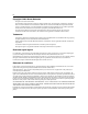
Using the Web-based management interface Figure 2 Web page layout Web browser toolbar Administration > System Information Summary Configuration Fault Statistics Application Administration System Info(option) Security Logout Reset Support Menu Business Policy Switch 2000 BayStack 460 HW:AB3 FW:V0.2E sysDescription SW:v1.0.0.
Using the Web-based management interface 37 Table 1 lists the main headings in the Web-based management user interface and their associated options.
Using the Web-based management interface Table 1 Main headings and options Main menu titles Options Support Help Release Notes Manuals Upgrades *Has additional menus. Tools are provided in the menu to assist you in navigating the Web-based management interface. Caution: Web browser capabilities such as page bookmarking, refresh, and page forward and page back, function as they would in any other Web site.
Using the Web-based management interface 39 Management page When you click a menu option, the corresponding management page opens. Figure 3 shows the page displayed for the Administration > Security > Console option. Figure 3 Console page A page is composed of one or more of the following elements: • Tables and input forms The gray cells in a page are display only, and white cells are input fields. • Check boxes You enable or disable a selection by clicking a check box.
Using the Web-based management interface Table 3 describes the icons that may appear on a pages to assist you in navigation. Table 3 Page buttons and icons Icon Name Description Modify Accesses a modification page for the selected row. View Accesses a view only statistics page for the selected row. Delete Deletes a row. Pie Chart Displays statistics information in a pie chart format. Bar Graph Displays statistics information in a bar graph format.
Chapter 2 Administering the switch The administrative options available to you are: • • • • • • “Viewing general information,” next “Configuring system security” on page 44 “Logging on to the management interface” on page 47 “Resetting the BPS 2000” on page 49 “Resetting the BPS 2000 to system defaults” on page 50 “Logging out of the management interface” on page 51 For more information on the feature discussed in this chapter, refer to Using the Business Policy Switch 2000 Software Version 2.0.
Administering the switch Viewing system information You can view an image of the BPS 2000 switch or an image of your entire stack configuration, information about the host device (or stack) and, if provided, the contact person or manager for the switch. The System Information page is also the Web-based management interface home page. To view system information: ➨ From the main menu, choose Administration > System Information. The System Information page opens (Figure 4).
Administering the switch 43 Table 4 describes the items on the System Information page. Table 4 System Information page items Item Description sysDescription The default description of the Business Policy Switch 2000, including the hardware, firmware, software, and ISVN version numbers. sysUpTime The elapsed time since the last network management portion of the system was last re-initialized. sysName The name created by the network administrator to identify the switch, for example Finance Group.
Administering the switch Table 5 describes the items on the CPU/Memory Utilization page. Table 5 CPU/Memory Utilization page items Section Item Range Description CPU Utilization From System Boot-Up 1....100 Displays percentage of time system has been busy since boot-up. Last 10 Seconds 1..100 Displays percentage of time system has been busy during the last 10 seconds. Last 1 Minute 1..100 Displays percentage of time system has been busy during the last 1 minute. Last 10 Minutes 1..
Administering the switch 45 The selected password page opens (Figure 6). Note: The title of the page corresponds to the menu selection you choose. In Figure 6, the network administrator selected Administration > Security > Console. Figure 6 Console password setting page Note: Console, Telnet, and Web settings share the same switch and stack password type and password. Table 6 describes the items on the Console page.
Administering the switch Table 6 Console page items Section Item Setting Description Read-Only Stack Password 1..15 alphanumeric string Type the read-only password setting for the read-only access user. Read-Write Stack Password 1..15 alphanumeric string Type the read-write password setting for the read-write access user. 2 Type the information, or make a selection from the list. 3 Click Submit.
Administering the switch 47 Table 7 RADIUS page items Item Setting Description UDP RADIUS Port Integer Type the UDP RADIUS port number. RADIUS Shared Secret 1..16 Type a unique character string to create a secret password. 2 Type the information. 3 Click Submit.
Administering the switch 1 In the Username text box, type RO for read-only access or RW for read-write access. 2 In the Password text box, type your password. 3 Click Log On. The System Information home page opens (Figure 9). Figure 9 System Information home page With Web access enabled, the switch can support up to four concurrent Web page users. Two predefined user levels are available, and each user level has a corresponding username and password.
Administering the switch 49 Resetting the BPS 2000 You can reset a standalone switch, a specific unit in a stack configuration, or an entire stack without erasing any configured switch parameters. While resetting, the switch initiates a self-test that comprises various diagnostic routines and subtests. The LEDs display various patterns to indicate that the subtests are in progress. (Resetting means rebooting in this context.
Administering the switch Resetting the BPS 2000 to system defaults You can reset a standalone switch, a specific unit in a stack configuration, or an entire stack, replacing all configured switch parameters with the factory default values. Caution: If you choose reset to default settings, all configured settings are replaced with factory default settings when you click Submit (Stack Operational Mode is not reset to factory default}.
Administering the switch 2 From the list, choose to reset the switch only to system defaults, or the entire stack. 3 Click Submit. 51 Note: If you have not configured system password security, a reset returns you to the home page, as shown in Figure 1 on page 35. If you have configured system password security, a reset returns you to a log on page, as shown in Figure 8 on page 47.
Administering the switch 209570-C
Chapter 3 Viewing summary information The summary information options are: • • • • • “Viewing stack information,” next “Viewing summary switch information” on page 55 “Viewing switch information in real time” on page 57 “Changing stack numbering” on page 60 “Identifying unit numbers” on page 62 Note: To access the software version 2.0 features in a mixed stack, you must access a BPS 2000 unit.
Viewing summary information To view stack information: 1 From the main menu, choose Summary > Stack Information. The Stack Information page opens (Figure 12). Figure 12 Stack Information page Table 9 describes the fields on the Stack Information and Stack Inventory sections of the Stack Information page.
Viewing summary information 55 Table 9 Stack Information page fields (continued) Section Fields Description Software Version The current running software version. Operational State The current operational state of the stack. The operational states are: Other, Not Available, Removed, Disabled, Normal, Reset in Progress, Testing, Warning, Non Fatal Errors, Fatal Error, and Not Configured. 2 In the upper-left corner of the Stack Information page, click the number of the device you want to view.
Viewing summary information Table 10 describes the fields on the Switch Information page. Table 10 Switch Information page fields Item Description Unit Select the number of the device on which to view summary information. The page is updated with information about the selected switch. For more information on stack numbering, see page 60. Module Description The factory set description of the policy switch. MDA Description The factory set description of the sub-component/MDA.
Viewing summary information 57 Viewing switch information in real time You can display the port and LED status information of a selected policy switch in real time. To display a physical view of the policy switch: 1 From the main menu, choose Summary > Switch View. The Switch View page opens in a separate Web browser (Figure 14). Figure 14 Switch View page Using Web-based Management for the Business Policy Switch 2000 Software Version 2.
Viewing summary information Note: You may be presented with a security warning to click on before the switch view appears. Table 11 describes the fields on the Switch View page. Table 11 BPS 2000 switch LED descriptions Label Type Color State Meaning Pwr Power status Green On DC power is available to the switch’s internal circuitry. Off No AC power to switch or power supply failed. On Self-test passed successfully and switch is operational.
Viewing summary information 59 Table 11 BPS 2000 switch LED descriptions (continued) Label Type Color State Meaning Base Base mode Green On The switch is configured as the stack base unit. Off The switch is not configured as the stack base unit (or is in standalone mode). Amber On This unit is operating as the stack configuration’s temporary base unit. This condition occurs automatically if the base unit (directly downstream from this unit) fails.
Viewing summary information Changing stack numbering If your system is set to “stack” operational mode, you can view existing stack numbering information and renumber the devices in your stack framework. For information on how to set your system’s operational mode, see “Setting system operational modes” on page 128. Note: The unit number does not affect the base unit designation. To view or renumber devices within the stack framework: 1 From the main menu, choose Summary > Stack Numbering.
Viewing summary information 61 Table 12 Stack Numbering Setting page fields (continued) Item Range Description MAC Address XX.XX.XX.XX.XX.XX MAC address of the corresponding unit listed in the Current Unit Number field. New Unit Number 1..8, None Choose a new number to assign to your selected policy switch. Note: If you leave the field blank, the system automatically selects the next available number. 2 Choose the new number to assign to your switch. 3 Click Submit.
Viewing summary information Identifying unit numbers You can identify the unit numbers of the switches participating in a stack configuration by viewing the LEDs on the front panel of each switch. To identify unit numbers in your configuration: 1 From the main menu, choose Summary > Identify Unit Numbers. The Identify Unit Numbers page opens (Figure 16).
Chapter 4 Configuring the switch The switch configuration options available to you are: • “Configuring BootP, IP, and gateway settings,” (next) • “Modifying system settings” on page 67 • “About SNMP” on page 68 • “Configuring SNMPv1” on page 69 • “Configuring SNMPv3” on page 70 • “Configuring SNMP traps” on page 89 • “Configuring EAPOL-based security” on page 91 • “Managing remote access by IP address” on page 94 • “Configuring MAC address-based security” on page 96 • “Viewing learned
Configuring the switch Configuring BootP, IP, and gateway settings You can configure your BootP mode settings, create and modify your in-band stack and in-band switch IP addresses and in-band subnet mask parameters, and configure the IP address of your default gateway. Beginning with software version 2.0, you can configure IP addresses for individual units in a stack. Note: Settings take effect immediately when you click Submit.
Configuring the switch 65 Figure 18 IP page for a stack Note: To change the IP information for a specific unit in the stack, choose that unit and enter the desired IP information into the In-Band Switch IP address field. Table 13 describes the items on the IP page.
Configuring the switch Table 13 IP page items Section Item Range Description BootP or Last Address Choose this mode to inform the switch, at each startup, to obtain its IP configuration using BootP. If the BootP request fails, the switch uses the network parameters stored in its non-volatile memory. Note: Valid parameters obtained in using BootP always replace current information stored in the non-volatile memory.
Configuring the switch 67 Modifying system settings You can create or modify the system name, system location, and network manager contact information. Note: The configurable parameters on the System page are displayed in a read only-format on the Web-based management user interface System Information home page (see Figure 1 on page 35). To configure system settings: 1 From the main menu, choose Configuration > System. The System page opens (Figure 19).
Configuring the switch Table 14 describes the items on the System page. Table 14 System page items Item Range System Description Description The factory set description of the hardware and software versions. System Object ID The character string that the vendor created to uniquely identify this device. System Up Time The elapsed time since the last network management portion of the system was last re-initialized. Note: This field is updated only when the screen is redisplayed. System Name 0..
Configuring the switch 69 Configuring SNMPv1 You can configure SNMPv1 read-write and read-only community strings, enable or disable trap mode settings, and/or enable or disable the Autotopology feature. The Autotopology feature, when enabled, performs a process that recognizes any device on the managed network and defines and maps its relation to other network devices in real time.
Configuring the switch Table 15 describes the items on the SNMPv1 page. Table 15 SNMPv1 page items Section Item Community String Read-Only Setting Community String Range Description 1..32 Type a character string to identify the community string for the SNMPv1 read-only community, for example, public or private. The default value is public. Read-Write Community String 1..
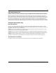
Configuring the switch 71 Figure 21 System Information page Table 16 describes the fields on the System Information section of the SNMPv3 System Information page. Table 16 System Information section fields Item Description SNMP Engine ID The SNMP engine’s identification number. SNMP Engine Boots The number of times that the SNMP engine has re-initialized itself since its initial configuration. SNMP Engine Time The number of seconds since the SNMP engine last incremented the snmpEngineBoots object.
Configuring the switch Table 17 describes the fields on the SNMPv3 Counters section of the SNMPv3 System Information page. Table 17 SNMPv3 Counters section fields Item Description Unavailable Contexts The total number of packets dropped by the SNMP engine because the context contained in the message was unavailable. Unknown Contexts The total number of packets dropped by the SNMP engine because the context contained in the message was unknown.
Configuring the switch 73 Figure 22 User Specification page Table 18 describes the items on the User Specification Table section of the User Specification page. Table 18 User Specification Table section items Item and MIB association Description Deletes the row. User Name (usmUserSecurityName) The name of an existing SNMPv3 user.
Configuring the switch Table 19 describes the items on the User Specification Creation section of the User Specification page. Table 19 User Specification Creation section items Item and MIB association Range Description User Name 1..32 Type a string of characters to create an identity for the user.
Configuring the switch 75 Deleting an SNMPv3 system user configuration To delete an existing SNMPv3 user configuration: 1 From the main menu, choose Configuration > SNMPv3 > User Specification. The User Specification page opens (Figure 22). 2 In the User Specification Table, click the Delete icon for the entry you want to delete. A message opens prompting you to confirm your request. 3 Do one of the following: • • Click Yes to delete the SNMPv3 user configuration.
Configuring the switch Figure 23 Group Membership page Table 20 describes the items on the Group Membership page. Table 20 Group Membership page items Item and MIB association Range Description Deletes the row. Security Name (vacmSecurityToGroupStatus) 1..32 Type a string of character to create a security name for the principal which is mapped by this entry to a group name.
Configuring the switch 2 In the Group Membership Creation section, type information in the text boxes, or select from a list. 3 Click Submit. 77 The new entry appears in the Group Membership Table. Deleting an SNMPv3 group membership configuration To delete an SNMPv3 group membership configuration: 1 From the main menu, choose Configuration > SNMPv3 > Group Membership. The Group Membership page opens (Figure 23).
Configuring the switch Configuring SNMPv3 group access rights You can view a table of existing SNMPv3 group access rights configurations, and you can create or delete a group’s SNMPv3 system-level access rights. Creating an SNMPv3 group access rights configuration To create a group’s SNMPv3 system-level access right configuration: 1 From the main menu, choose Configuration > SNMPv3 > Group Access Rights. The Group Access Rights page opens (Figure 24).
Configuring the switch 79 Table 21 describes the items on the Group Access Rights page. Table 21 Group Access Rights page items Item and MIB association Range Description Deletes the row. Group Name (vacmAccessToGroupStatus) 1..32 Type a character string to specify the group name to which access is granted. Security Model (vacmAccessSecurityModel)l (1) SNMPv1 (2) SNMPv2c (3) USM Choose the security model to which access is granted.
Configuring the switch 2 In the Group Access Table, click the Delete icon for the entry you want to delete. A message opens prompting you to confirm your request. 3 Do one of the following: • • Click Yes to delete the group access configuration. Click Cancel to return to the Group Access Rights page without making changes. Note: This Group Access Table section of the Group Access Rights page contains hyperlinks to the Management Information View page.
Configuring the switch 81 Figure 25 Management Information View page Table 22 describes the items on the Management Information View page. Table 22 Management Information View page items Item and MIB association Range Description Deletes the row. View Name (vacmViewTreeFamilyViewName) 1..32 Type a character string to create a name for a family of view subtrees. View Subtree (vacmViewTreeFamilySubtree) X.X.X.X.X...
Configuring the switch 2 In the Management Information Creation section, type information in the text boxes, or select from a list. 3 Click Submit. The new entry appears in the Management Information Table (Figure 25). Deleting an SNMPv3 management information view configuration To delete an existing SNMPv3 management information view configuration: 1 From the main menu, choose Configuration > SNMPv3 > Management Info View. The Management Information page opens (Figure 25).
Configuring the switch 83 Creating an SNMPv3 system notification configuration To create an SNMPv3 system notification configuration: 1 From the main menu, choose Configuration > SNMPv3 > Notification. The Notification page opens (Figure 26). Figure 26 Notification page Table 23 describes the items on the Notification page. Table 23 Notification page items Item and MIB association Range Description Deletes the row. Notify Name (snmpNotifyRowStatus) 1..
Configuring the switch 2 In the Notification Creation section, type information in the text boxes, or select from a list. 3 Click Submit. The new entry appears in the Notification Table (Figure 26). Note: This Notification Table section of the Notification page contains hyperlinks to the Target Parameter page. For more information, see “Configuring an SNMPv3 management target parameter” on page 87.
Configuring the switch 85 Configuring an SNMPv3 management target address You can view a table of existing SNMPv3 management target configurations, create SNMPv3 management target address configurations that associate notifications with particular recipients and delete SNMPv3 target address configurations. Creating an SNMPv3 target address configuration To create an SNMPv3 target address configuration: 1 From the main menu, choose Configuration > SNMPv3 > Target Address.
Configuring the switch Table 24 describes the items on the Target Address page. Table 24 Target Address page items Item and MIB association Range Description Deletes the row. Target Name (snmpTargetAddrName) 1..32 Type a character string to create a target name. Target Domain (snmpTargetAddrTDomain) 1..32 The transport type of the address contained in the snmpTargetAddrTAddress object. Target Address (snmpTargetAddrTAddress) XXX.XXX.XXX.
Configuring the switch 87 Deleting an SNMPv3 target address configuration To delete an SNMPv3 target address configuration: 1 From the main menu, choose Configuration > SNMPv3 > Target Address. The Target Address page opens (Figure 27). 2 In the Target Address Table, click the Delete icon for the entry you want to delete. A message opens prompting you to confirm your request. 3 Do one of the following: • • Click Yes to delete the target address configuration.
Configuring the switch Figure 28 Target Parameter page Table 25 describes the items on the Target Parameter page. Table 25 Target Parameter page items Item Range Description Deletes the row. Parameter Tag (snmpTargetParamsRowStatus) 1..32 Type a unique character string to identify the parameter tag. Msg Processing Model (snmpTargetParamsMPModel) (0) SNMPv1 Choose the message processing model to be used when (1) SNMPv2c generating SNMP messages using this entry.
Configuring the switch 89 Deleting an SNMPv3 target parameter configuration To delete an SNMPv3 target parameter configuration: 1 From the main menu, choose Configuration > SNMPv3 > Target Address. The Target Address page opens (Figure 27). 2 In the Target Parameter Table, click the Delete icon for the entry you want to delete. A message opens prompting you to confirm your request. 3 Do one of the following: • • Click Yes to delete the target parameter configuration.
Configuring the switch Figure 29 SNMP Trap Receiver page Table 26 describes the items on the Trap Receiver Table and Trap Receiver Creation sections of the SNMP Trap Receiver page. Table 26 SNMP Trap Receiver page items Items Range Description Deletes the row. Trap Receiver Index 1..4 Choose the number of the trap receiver to create or modify. IP Address XXX.XXX.XXX.XXX Type the network address for the SNMP manager that is to receive the specified trap. Community 0..
Configuring the switch 2 91 In the Trap Receiver Table, click the Delete icon for the entry you want to delete. A message opens prompting you to confirm your request. 3 Do one of the following: • • Click Yes to delete the SNMP trap receiver configuration. Click Cancel to return to the table without making changes. Configuring EAPOL-based security Beginning with software version 1.1, you can configure security based on the Extensible Authentication Protocol over LAN (EAPOL) protocol.
Configuring the switch Figure 30 EAPOL Security Configuration page (1 of 2) Figure 31 EAPOL Security Configuration page (2 of 2) 209570-C
Configuring the switch 93 Table 27 describes the fields on the EAPOL Security Configuration page. Table 27 EAPOL Security Configuration page fields Section Item Range Description EAPOL Administrative State Setting EAPOL Administrative State (1) Enabled (2) Disabled Enables or disables EAPOL-based security. EAPOL Security Setting Unit Displays the unit you are viewing. Port 1 to 28 Displays the port number. Initialize (1) Yes (2) No Activates EAPOL state on this port.
Configuring the switch 2 Complete fields as described in the table. 3 Click Submit. Managing remote access by IP address Beginning with software version 1.2, you can configure the remote access you allow. You can specify up to 10 IP addresses to allow Web access, SNMP access, or Telnet access to the BPS 2000. To configure remote access using the Web-based management system: 1 From the main menu of the Business Policy Switch 2000 Web-based Manager, choose Configuration > Remote Access.
Configuring the switch 95 Figure 32 Remote Access page Table 28 describes the fields on the Remote Access page. Table 28 Remote Access page fields Section Item Range Description Remote Access Settings Telnet/Access (1)Allowed (2) Disallowed Allows Telnet access. Telnet/Use List (1) Yes (2) No Restricts Telnet access to the specified 10 source IP addresses. SNMP/Access (1)Allowed (2) Disallowed Allows SNMP access.
Configuring the switch Table 28 Remote Access page fields (continued) Section Allowed Source IP and Subnet Mask Item Range Description Web/Use List (1) Yes (2) No Restricts Web access to the specified 10 source IP addresses. Allowed Source IP XXX.XXX.XXX. XXX Enter the source IP address you want to allow switch access. Allowed Source Mask XXX.XXX.XXX. XXX Enter the source IP mask you want to allow switch access. 2 Complete fields as described in the table. 3 Click Submit.
Configuring the switch 97 Beginning with software version 2.0, you can configure the BPS 2000 to drop all packets having a specified MAC destination address (DA). You can create a list of up to 10 MAC DAs you want to filter.The packet with the specified MAC DA will be dropped regardless of the ingress port, source address (SA) intrusion, or VLAN membership. Note: Ensure that you do not enter the MAC address of the switch or stack you are working on.
Configuring the switch Figure 33 Security Configuration page Table 29 describes the items on the Security Configuration page. Table 29 Security Configuration page items Section Item Range Description MAC Address Security Setting MAC Address Security (1) Enabled (2) Disabled Enables the MAC address security features. MAC Address Security SNMP-Locked (1) Enabled (2) Disabled Enables locking SNMP, so that you cannot use SNMP to modify the MAC address security features.
Configuring the switch 99 Table 29 Security Configuration page items (continued) Section Item Range Description Partition Time 1 to 65535 Sets the time to partition a port on intrusion. Note: Use this field only if the Partition Port on Intrusion Detected field is set to Enabled. DA Filtering on Intrusion Detected MAC Security Table/ Clear by Ports MAC Security Table/ Learn by Ports (1) Enabled (2) Disabled Enables you to isolate the intruding node (discard) the packets.
Configuring the switch Figure 34 Port Lists page Table 30 describes the items on the Ports Lists page. Table 30 Ports Lists page items Item Range Description Entry These are the lists of ports. Action Allows you to add or delete ports to the lists. Port List Displays which ports are associated with each list. 2 To add or delete ports to a list, click the icon in the Action column in the list row you want. The Port List View, Port List page opens (Figure 35).
Configuring the switch 101 Figure 35 Port List View, Port List page 3 a Click the ports you want to add to the selected list or click None. b To delete a port from a list, uncheck the box by clicking it. c Click Submit. From the main menu, choose Application > MAC Address Security > Security Configuration. The Security Configuration page opens (Figure 33). 4 In the MAC Security Table section, click the icon in the Action column of the Learn By Ports row.
Configuring the switch c Click Submit. 5 In the MAC Security Table section, choose Enabled in the Current Learning Mode column of the Learn By Ports row. 6 Click Submit. Note: You cannot include any of the port values you have chosen for the secure ports field. Adding MAC addresses To add MAC address to the MAC address-based security system: 1 In the main menu, choose Applications > MAC Address Security > Security Table. It may take awhile for the required addresses to be learned.
Configuring the switch 103 Table 31 describes the items on the Security Table page. Table 31 Security Table page items Section Item Range MAC Address Security Table Action Allows you to delete a MAC address. Address Displays the MAC address. Allowed Source MAC Address Security Table Entry Creation 2 (1) Unit/Port (2) Entry Description Displays the entry through which the MAC address is allowed. MAC Address Enter the MAC address you want to allow to access the switch.
Configuring the switch 1 From the main menu, choose Application > MAC Address Security > Security Configuration. The Security Configuration page opens (Figure 33). 2 In the MAC Security Table section, click the icon in the Action column of the Clear By Ports row. The Port List View, Clear by Ports page opens (Figure 38). Figure 38 Port List View, Clear by Ports page 3 Select the ports you want to clear or click None. 4 Click Submit.
Configuring the switch 105 Figure 39 Port Configuration page Table 32 describes the items on the Port Configuration page. Table 32 Port Configuration page items Item Range Description Unit 1 to 8 Displays the unit number of the ports shown in the table. Port 1 to 28 Lists each port on the unit. Trunk Blank, 1 to 6 Displays the MultiLink Trunk that the port belongs to. Security (1) Enabled (2) Disabled Enables MAC address-based security on that port.
Configuring the switch • • In the Ports List View, Learn by Ports page (Figure 36), click on the checkmark of a selected port to remove that port from those that learn MAC addresses. In the Port Configuration page (Figure 39), click Disabled to remove that port from the MAC address-based security system; it will disable all MAC address-based security on that port.
Configuring the switch 107 Table 33 DA MAC Filtering page items Section DA MAC Filtering Entry Creation Item Range Description MAC Address 1 -10 Displays list of MAC DAs you want filtered. DA MAC Address XX:XX:XX:XX:XX:XX Enter the MAC DA you want to filter. Note: Ensure that you do not enter the MAC address of the management station. 2 In the DA MAC Filtering Entry Creation area, enter the MAC DA you want to filter. You can list up to 10 MAC DAs to filter. 3 Click Submit.
Configuring the switch Viewing learned MAC addresses by VLAN You can view MAC addresses and their associated port or trunk that the switch or stack configuration has learned, based on the VLAN you select. To view learned MAC addresses and their associated port or trunk: 1 From the main menu, choose Configuration > MAC Address Table. The MAC Address Table page opens (Figure 41).
Configuring the switch 109 Table 34 describes the items on the MAC Address Table page. Table 34 MAC Address Table page items Section Item Range Description MAC Address Setting Aging Time 10..1000000 Type the timeout period, in seconds, for aging out dynamically learned forwarding information. If the entry is inactive for a period of time that exceeds the specified aging time, the address is removed. Note: Nortel Networks recommends that you use the default value of 300 seconds.
Configuring the switch Figure 42 Find MAC Address Table page Table 34 on page 109 describes the items on the Find MAC Address Table page. 2 In the MAC Address Setting section, type the MAC address you want to search for. 3 Click Submit to enter the request. If the address is located, it is shown in the first row in the MAC Address Table section. If the address is not located, the system response “Not Found” is shown to the right of the Find MAC Address input field.
Configuring the switch 111 Configuring port’s autonegotiation, speed, duplex, status, and alias You can configure a specific switch port or all switch ports to autonegotiate for the highest available speed of the connected station or you can set the speed for selected switch ports. Autonegotiation is not supported on fiber optic ports. Note: You cannot disable autonegotiation using the BPS2000-1GT or BPS2000-2GT MDA ports; you cannot enable autonegotiation using the BPS2000-2GE MDA ports.
Configuring the switch Figure 43 Port Management page 209570-C
Configuring the switch 113 Table 35 describes the items on the Port Management page. Table 35 Port Management page items Item Range Port Description The switch port number of the corresponding row. To select the switch row, click the check box to the right.
Configuring the switch Table 35 Port Management page items Item Range Description Speed / Duplex (1) 10Mbs / Half (2) 10Mbs / Full (3) 100Mbs / Half (4) 100Mbs / Full (5) 1000Mbs / Full Choose the Ethernet speed you want the port to support. NOTE: Fiber optic ports can only be set to 100 Mb/s/Half or 100 Mb/s/Full. Use the High Speed Flow Control Configuration screen (next) to set autonegotiation for all gigabit ports.
Configuring the switch 115 Figure 44 High Speed Flow Control page Table 36 describes the items on the High Speed Flow Control page. Table 36 High Speed Flow Control page items Item Range Description Autonegotiation (1) Enabled (2) Disabled Choose to enable or disable the autonegotiation feature. NOTE: This field is disabled for all fiber optic ports. Additionally, you cannot disable this field for the ports on the BPS2000-1GT and BPS2000-2GT MDAs.
Configuring the switch Downloading switch images You can download the BPS 2000 software image that is located in non-volatile flash memory. To download the BPS 2000 software image, a properly configured Trivial File Transfer Protocol (TFTP) server must be present in your network, and the policy switch must have an IP address. To learn how to configure the switch or stack IP address, refer to “Configuring BootP, IP, and gateway settings” on page 64.
Configuring the switch 117 Figure 46 Software Download page for a Hybrid stack Table 37 describes the items on the Software Download page. Table 37 Software Download page items Item Range Description Current Running Version The version of the current running software. Local Store Version The local version of the software in the flash memory. BPS 2000 Image Filename 1..30 Type the software image load filename. BPS 2000 Diagnostics Filename 1..30 Type the diagnostics filename.
Configuring the switch The software download process automatically completes without user intervention. The process erases the contents of flash memory and replaces it with a new software image. Take care not to interrupt the download process until after it runs to completion (the process can take up to 10 minutes, depending on network conditions). When the download process is complete, the switch automatically resets and the new software image initiates a self-test.
Configuring the switch 119 Table 38 LED Indications during the software download process (continued) Phase Description LED Indications 3 The switch programs the new software image into the flash memory. 100 Mb/s port status LEDs (ports 1 to 8 only): The LEDs begin to turn on in succession beginning with port 1, which indicates that the new software image is being programmed into the switch’s flash memory.
Configuring the switch • • “Upgrading software in a Pure BPS 2000 stack or a standalone BPS 2000,” next “Upgrading software in a Hybrid stack” on page 121 Upgrading software in a Pure BPS 2000 stack or a standalone BPS 2000 To download, or upgrade, software in a Pure BPS 2000 stack or a standalone BPS 2000 unit: 1 From the main menu, choose Configuration > Software Download. The Software Download page opens (Figure 45). 2 In the BPS 2000 Image Filename field, enter the image file name.
Configuring the switch 121 Upgrading software in a Hybrid stack The physical order of the units and the unit numbering in the Hybrid stack does not affect the upgrading process at all. In addition, the cabling order regarding upstream/downstream neighbors does not affect the process. Before you attempt to download new software (or upgrade software) to a Hybrid (mixed) stack, you must ensure that the Interoperability Software Version Numbers (ISVN) are identical.
Configuring the switch 3 In the TFTP Server IP Address, enter the IP address of your TFTP load host. 4 In the Start TFTP Load of New Image field, choose BPS 2000 Image in the Start TFTP Load of New Image field. 5 Click Submit. The system resets, which may take a few minutes. The system opens to the System Information page (Figure 4). 6 From the main menu, choose Configuration > Software Download. 7 In the BPS 2000 Diagnostics Filename field, enter the name of the BPS 2000 diags file.
Configuring the switch 5 123 In the Start TFTP Load of New Image field, choose Both BPS 2000 and 450 Image. Note: If you do not download both the BPS 2000 and BayStack 410/450 images simultaneously, the stack may not form. 6 Click Submit. The system resets, which may take a few minutes. The system opens to the System Information page (Figure 4). 7 From the main menu, choose Configuration > Software Download. 8 In the 450 Image Filename field, enter the name of the other 450 image file.
Configuring the switch Refer to Using the Business Policy Switch 2000 Software Version 2.0 for further information on downloading software and upgrading software in standalone BPS 2000 units, in pure BPS 2000 stacks, and in mixed (Hybrid) stacks. Storing and retrieving a switch configuration file from a TFTP server You can store switch and stack configuration parameters on a Trivial File Transfer Protocol (TFTP) server.
Configuring the switch 125 Table 39 describes the items on the Configuration File page. Table 39 Configuration File page items Item Range Description Configuration Image Filename 1..32 Type the configuration file name. TFTP Server IP Address XXX.XXX.XXX.XXX Type the IP address of the TFTP load host. Copy Configuration Image to Server (1) Yes (2) No Choose whether or not to copy the configuration image to the server.
Configuring the switch Table 40 describes the requirements for storing or retrieving configuration parameters on a TFTP server. Table 40 Requirements for storing or retrieving configuration parameters on a TFTP server Requirements • The Configuration File feature can only be used to copy standalone switch configuration parameters to other standalone switches or to copy stack configuration parameters to other stack configurations.
Configuring the switch 127 Configuring port communication speed You can view the current console/communication port settings and configure the console port baud rate to match the baud rate of the console terminal. To view current console/communication port settings and configure console port speed: 1 From the main menu, choose Configuration > Console/Comm Port. The Console/Communication Port page opens (Figure 48).
Configuring the switch Setting system operational modes You can set the next stack mode operation of either a stack of BPS 2000 only, or a mixed stack of BPS 2000 and BayStack 450 and 410 switches. To set the next stack mode operation: 1 From the main menu, choose Configuration > Stack Operational Mode. The Stack Operational Mode Setting page opens (Figure 49). Figure 49 Stack Operational Mode page Table 43 describes the items on the Stack Operational Mode Setting page.
Chapter 5 Configuring remote network monitoring (RMON) The RMON management information base (MIB) is an interface between the RMON agent on a BayStack 450 switch or Business Policy Switch 2000 and RMON management applications such as the Web-based management user interface. It defines objects that are suitable for the management of any type of network. Some groups are specifically targeted for Ethernet networks. The RMON agent continuously collects statistics and proactively monitors the switch.
Configuring remote network monitoring (RMON) Configuring RMON fault threshold parameters Alarms are useful when you need to know when the value of some variable goes out of range. RMON alarms can be defined on any MIB variable that resolves to an integer value. String variables (such as system description) cannot be used as alarm variables. Creating an RMON fault threshold You can create the RMON threshold parameters for fault notification (alarms).
Configuring remote network monitoring (RMON) 131 Table 44 describes the items on the RMON Threshold page. Table 44 RMON Threshold page items Item Range Description Deletes the row. Index/Alarm Index 1..10 Type the unique number to identify the alarm entry. Target Integer The unit number and port number. Unit 1..8 Choose the switch on which to configure port alarms. Port 1..28 Choose the port on which to set an alarm.
Configuring remote network monitoring (RMON) Table 44 RMON Threshold page items (continued) Item Range Description Interval Type the time period (in seconds) to sample data and compare the data to the rising and falling thresholds. Sample/Alarm Sample (1) Absolute (2) Delta Choose the sampling method: Absolute: Absolute alarms are defined on the current value of the alarm variable. An example of an alarm defined with absolute value is card operating status.
Configuring remote network monitoring (RMON) 3 133 Do one of the following: • • Click Yes to delete the RMON threshold configuration. Click Cancel to return to the RMON Threshold page without making changes. Viewing the RMON fault event log RMON events and alarms work together to notify you when values in your network go out of a specified range. When values pass the specified ranges, the alarm is triggered and “fires.” The event specifies how the activity is recorded.
Configuring remote network monitoring (RMON) Table 45 describes the fields on the RMON Event Log page. Table 45 RMON Event Log page fields Item Description Time Stamp The time the event occurred. Description An implementation dependent description of the event that activated this log entry. Triggered By A comment describing the source of the event. ID The event that generated this log entry.
Configuring remote network monitoring (RMON) 135 Table 46 describes the fields on the System Log page. Table 46 System Log page fields Section Item Range Description System Log (View By) Display Unit 1..8 Choose the unit on which to display messages or clear messages. Display (1) Non Volatile Messages From (2) Volatile + Non Volatile Choose to display messages from Non Volatile memory (NVRAM) or Volatile (DRAM) and Non Volatile memory. The default settings is Non Volatile.
Configuring remote network monitoring (RMON) Viewing RMON Ethernet statistics You can gather and graph RMON Ethernet statistics in a variety of formats. To gather and graph RMON Ethernet statistics: 1 From the main menu, choose Statistics > RMON Ethernet. The RMON Ethernet page opens (Figure 53). Figure 53 RMON Ethernet page Table 47 describes the items on the RMON Ethernet page. Table 47 RMON Ethernet page items Item Description Displays statistics as a bar graph.
Configuring remote network monitoring (RMON) 137 Table 47 RMON Ethernet page items (continued) Item Description Packets The number of good packets received that were directed to the broadcast address. This does not include multicast packets. Broadcast The number of good packets received that were directed to the broadcast address. This does not include multicast packets. Multicast The number of good packets received that were directed to the multicast address.
Configuring remote network monitoring (RMON) Viewing RMON Ethernet statistics in a bar graph format To view RMON Ethernet statistics in a bar graph format: 1 From the main menu, choose Statistics > RMON Ethernet. The RMON Ethernet page opens (Figure 53). 2 In the port row of your choice, click the bar graph icon. The RMON Ethernet: Chart page appears in a bar graph format (Figure 54).
Configuring remote network monitoring (RMON) 139 Viewing RMON Ethernet statistics in a pie chart format To view RMON Ethernet statistics in a pie chart format: 1 From the main menu, choose Statistics > RMON Ethernet. The RMON Ethernet page opens (Figure 53). 2 In the port row of your choice, click the pie chart icon. The RMON Ethernet: Chart page appears in a pie chart format (Figure 55).
Configuring remote network monitoring (RMON) Viewing RMON history You can view a periodic statistical sampling of data from various types of networks. To view periodic statistical data: 1 From the main menu, choose Statistics > RMON History. The RMON History page opens (Figure 56).
Configuring remote network monitoring (RMON) 141 Table 48 describes the items on the RMON History page. Table 48 RMON History page items Section Item Description RMON History Statistics (View By) Unit Choose the unit number to be monitored. Port Choose the port number to be monitored. Displays statistics as a line graph. RMON History Statistics Table Start The value of the sysUPTime at the start of the interval over which this sample was measured.
Configuring remote network monitoring (RMON) Viewing RMON statistics in a line graph format You can view RMON statistical data in a line graph format. To view statistics in a line graph format: 1 From the main menu, choose Statistics > RMON History. The RMON History page opens (Figure 56). 209570-C 2 In the RMON History Statistics Table, click the line graph icon. 3 Click Back to return to the RMON History page.
Chapter 6 Viewing system statistics The options available to monitor system statistical data are: • “Viewing port statistics,” (next) • “Viewing all port errors” on page 148 • “Viewing interface statistics” on page 150 • “Viewing Ethernet error statistics” on page 153 • “Viewing transparent bridging statistics” on page 157 Note: To access the software version 2.0 features in a mixed stack, you must access a BPS 2000 unit.
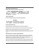
Viewing system statistics Figure 57 Port page Table 49 describes the items on the Port page. Table 49 Port page items Section Item Description Port Statistics (View By) Unit Choose the number of the switch to monitor. Port Choose the switch’s port number to monitor. Displays statistics in a bar graph format. Displays statistics in a pie chart format.
Viewing system statistics 145 Table 49 Port page items (continued) Section Item Description Port Statistics Table Packets The number of packets received/transmitted on this port, including bad packets, broadcast packets, and multicast packets. Multicast The number of good multicast packets received/transmitted on this port, excluding broadcast packets. Broadcasts The number of good broadcast packets received/transmitted on this port.
Viewing system statistics Table 49 Port page items (continued) Section Item Description Port Statistics Table, cont. Collisions The number of collisions detected on this port. Single Collisions The number of packets that were transmitted successfully on this port after a single collision. Multiple Collisions The number of packets that were transmitted successfully on this port after more than one collision.
Viewing system statistics 147 Viewing port statistics in a pie chart format You can view port statistics in a pie chart format. To view the displayed statistical information in a pie chart format: 1 In the Port Statistics Table, click the pie chart icon. The Port: Chart page opens in a pie chart format (Figure 58). Figure 58 Port: Chart page in a pie chart format Table 49 describes the items on the Port: Chart page. 2 Click Back to return to the Port page.
Viewing system statistics The Port: Chart page opens in a bar graph format (Figure 59). Figure 59 Port: Chart page in a bar graph format Table 49 describes the items on the Port: Chart page. 2 Click Back to return to the Port page. Viewing all port errors Beginning with software version 1.1, you can view all ports in the entire stack that have an error. If a particular port has no errors, it will not be displayed.
Viewing system statistics 149 Figure 60 Port Error Summary page Table 50 describes the read-only information displayed in the Port Error Summary Table. Table 50 Port Error Summary Table fields Item Description Unit Displays the unit number in the stack. Port Displays the port number of the unit. Status Displays the status of the port (Enabled/Disabled). Link Displays the link status of the port (Up/Down).
Viewing system statistics Viewing interface statistics You can view selected switch interface statistics. To view an interface’s statistical information: 1 From the main menu, choose Statistics > Interface. The Interface page opens (Figure 61).
Viewing system statistics 151 Table 51 describes the items on the Interface page. Table 51 Interface page items Item Description Displays statistics in a bar graph format. Displays statistics in a pie chart format. Port The port number corresponding to the selected switch. In Octets The number of octets received on the interface, including framing characters. Out Octets The number of octets transmitted out of the interface, including framing characters.
Viewing system statistics Viewing interface statistics in a pie chart format You can view interface statistics in a pie chart format. To view interface statistics in a pie chart format: 1 From the main menu, choose Statistics > Interface. The Interface page opens (Figure 61). 2 In the port row of your choice, click the pie chart icon. The Interface: Chart page opens in a pie chart format (Figure 62).
Viewing system statistics 153 The Interface page opens (Figure 61). 2 In the port row of your choice, click the bar graph icon. The Interface: Chart page opens in a bar graph format (Figure 62). Figure 63 Interface: Chart in a bar graph format Table 51 describes the items on the Interface: Chart page. 3 To update the statistical information, click Update, or click Back to return to the Interface page.
Viewing system statistics Figure 64 Ethernet Errors page Table 52 describes the items on the Ethernet Errors page. Table 52 Ethernet Errors page items Item Description Displays statistics in a bar graph format. Displays statistics in a pie chart format. Port The port number corresponding to the selected switch. Alignment Errors The number of frames received on a particular interface that are not an integral number of octets in length and do not pass the FCS check.
Viewing system statistics Table 52 155 Ethernet Errors page items (continued) Item Description SQE Test Errors The number of times that the SQE TEST ERROR message is generated by the PLS sublayer for a particular interface. The SQE TEST ERROR is defined in section 7.2.2.2.4 of ANSI/IEEE 802.3-1985, and its generation is described in section 7.2.4.6 of the same document.
Viewing system statistics Figure 65 Ethernet Error: Chart in a pie chart format Table 53 describes the items on the Ethernet Errors: Chart page. 3 To update the statistical information, click Update, or click Back to return to the Ethernet Errors page. Viewing Ethernet error statistics in a bar graph format You can view Ethernet Errors statistics in a bar graph format. To view Ethernet errors statistics in a bar graph format: 1 From the main menu, choose Statistics > Ethernet Errors.
Viewing system statistics 157 Figure 66 Ethernet Error: Chart in a bar graph format Table 52 describes the items on the Ethernet Errors: Chart page. 3 To update the statistical information, click Update, or click Back to return to the Ethernet Errors page. Viewing transparent bridging statistics You can view the transparent bridging statistics measured for each monitored interface on the device. To view transparent bridging statistics: 1 From the main menu, choose Statistics > Transparent Bridging.
Viewing system statistics Figure 67 Transparent Bridging page Table 53 describes the items on the Transparent Bridging page. Table 53 Transparent Bridging page items Item Description Displays statistics in a bar graph format. Displays statistics in a pie chart format. Port The port number that corresponds to the selected switch. In Frames (dot1dTpPortInFrames) The number of frames that have been received by this port from its segment.
Viewing system statistics 2 159 In the upper-left hand corner, click on the unit number of the device to monitor. The page is updated with statistics about the selected device and its corresponding port number. 3 To refresh the statistical information, click Update. Viewing transparent bridging statistics in a pie chart format You can view measured transparent bridging statistics in a pie chart format.
Viewing system statistics Viewing transparent bridging statistics in a bar graph format You can view measured transparent bridging statistics in a bar graph format. To view transparent bridging statistics in a bar graph format: 1 From the main menu, choose Statistics > Transparent Bridging. The Transparent Bridging page opens (Figure 61). 2 In the port row of your choice, click the bar graph icon. The Transparent Bridging: Chart page opens in a bar graph format (Figure 69).
Chapter 7 Configuring application settings The options available to configure application settings are: • “Configuring port mirroring,” (next) • “Configuring rate limiting” on page 165 • “Configuring IGMP” on page 167 • “Viewing Multicast group membership configurations” on page 169 • “Creating and managing virtual LANs (VLANs)” on page 171 • “Configuring VLANs” on page 173 • “Configuring broadcast domains” on page 188 • “Viewing VLAN port information” on page 190 • “Managing spanning
Configuring application settings Configuring port mirroring The BPS 2000 supports port mirroring to analyze traffic. You can view existing port mirroring activity and you can configure a specific switch port to mirror up to two specified ports or two MAC addresses. When you configure port mirroring, you have the option to specify either port-based monitoring or address-based monitoring. Refer to Using the Business Policy Switch 2000 Software Version 2.0 for configuration guidelines for port-mirroring.
Configuring application settings 163 Table 54 describes the items on the Port Mirroring page.
Configuring application settings Table 55 describes the port-based monitoring modes. Table 55 Port-based monitoring modes Item Description Disabled Choose this option to disable port-based monitoring. The default setting is Disabled. --> Port X Choose this option to monitor all traffic received by port X. Port X --> Choose this option to monitor all traffic transmitted by port X. <-- --> Port X Choose this option to monitor all traffic received and transmitted by port X.
Configuring application settings 165 Configuring rate limiting You can view the current forwarding rate of broadcast and/or multicast packets, and configure the BPS 2000 to limit the forwarding rate of broadcast and multicast packets on each interface. When you configure rate limiting, you are setting the percentage of port bandwidth allowed for a packet type. When the threshold is exceeded, additional packets are discarded.
Configuring application settings Table 57 describes the items on the Rate Limiting page. Table 57 Rate Limiting page items Item Range Description Port 1..28 The selected unit’s port number. The normal port range is 1 to 28. Note: A standard unit with MDA has a normal range of 25, 26, 28. Packet Type (1) Multicast (2) Broadcast (3) Both Choose the packet type to view on the table.
Configuring application settings 167 Configuring IGMP You can configure a VLAN’s switch ports to optimize IP multicast packets in a bridged Ethernet environment, and you can view a table of existing IGMP configurations. For more information about IGMP configuration, see Using the Business Policy Switch 2000 Software Version 2.0 (208700-C). To configure IGMP: 1 From the main menu, choose Application > IGMP > IGMP Configuration. The IGMP Configuration page opens (Figure 72).
Configuring application settings Table 58 IGMP Configuration page items Item Description Robust Value The predetermined value set by the administrator to offset expected packet loss on a subnet. If packet losses on a subnet are unacceptably high, the Robust Value field can be increased to a higher value. Note: This field affects only the VLAN specified in the page’s VLAN field. Query Time 2 The query interval (the interval between general queries sent by the multicast router).
Configuring application settings 169 Table 59 IGMP: VLAN Configuration page items (continued) Item Range Description Proxy (1) Enabled (2) Disabled Choose to enable or disable the proxy feature. This feature allows the switch to consolidate IGMP Host Membership Reports received on its downstream ports and to generate a consolidated proxy report for forwarding to its upstream neighbor. Note: This field affects all VLANs. The default setting is Enabled. Robust Value 1..
Configuring application settings To view multicast group membership configurations for a selected VLAN: 1 From the main menu, choose Application > IGMP > IGMP Multicast Group. The IGMP Multicast Group Membership page opens (Figure 74). Figure 74 IGMP Multicast Group Membership page Table 60 describes the items on the IGMP Multicast Group Membership page.
Configuring application settings 171 Creating and managing virtual LANs (VLANs) A VLAN is a collection of switch ports that make up a single broadcast domain. You can configure a VLAN for a single switch, or for multiple switches. When you create a VLAN, you can control traffic flow and ease the administration of moves, adds, and changes on the network, by eliminating the need to change physical cabling.
Configuring application settings Port-based VLANs A port-based VLAN is a VLAN in which the ports are explicitly configured to be in the VLAN. When you create a port-based VLAN on a switch, you assign a VLAN identification number (VLAN ID) and specify which ports belong to the VLAN. The VLAN ID is used to coordinate VLANs across multiple switches. With software version 1.1 and higher, the automatic PVID feature automatically sets the PVID when you configure a port-based VLAN.
Configuring application settings 173 Configuring VLANs You can create VLANs by assigning switch ports, MAC SA, and protocols as VLAN members and you can designate an existing VLAN to act as the management VLAN. Note: To access the software version 2.0 features in a mixed stack, you must access a BPS 2000 unit.
Configuring application settings Table 61 describes the items on the VLAN Configuration page. Table 61 VLAN Configuration page items Section Item VLAN Table Description Displays a modification page. Deletes the row. VLAN The number assigned to the VLAN when the VLAN was created. VLAN Name The name assigned to the VLAN when the VLAN was created. VLAN Type The base-type assigned when the VLAN was created. The base types are: Port-based, IP Subnet-based, Protocol-based, and MAC SA-based.
Configuring application settings 175 Creating a port-based VLAN To create a port-based VLAN: 1 From the main menu choose Application > VLAN > VLAN Configuration. The VLAN Configuration page opens (Figure 75). 2 In the VLAN Creation section, choose Port. 3 Click Create VLAN. The VLAN Configuration: Port Based setting page opens (Figure 76). Figure 76 VLAN Configuration: Port Based setting page Table 62 describes the items on the VLAN Configuration: Port Based setting page.
Configuring application settings 4 Type information in the text boxes, or select from a list. 5 Do one of the following: • • Click Submit. Click Back to return to the VLAN Configuration page without making changes. The new port-based VLAN configuration appears in the VLAN Table on the VLAN Configuration page (Figure 75). Modifying a port-based VLAN To modify an existing port-based VLAN: 1 From the main menu, choose Application > VLAN > VLAN Configuration.
Configuring application settings 177 Table 63 describes the items on the VLAN Configuration: Port Based modification page. Table 63 VLAN Configuration: Port Based modification page items Item Description VLAN The number assigned to the VLAN when the VLAN was created. VLAN Name (Re)name the VLAN. Learning Constraint The type of learning constraint selected when the VLAN was created. The learning constraint choices are IVL and SVL.
Configuring application settings Creating a protocol-based VLAN To create a protocol-based VLAN: 1 From the main menu, choose Application > VLAN > VLAN Configuration. The VLAN Configuration page opens (Figure 75). 2 In the VLAN Creation section, choose Protocol. 3 Click Create VLAN. The VLAN Configuration: Protocol Based setting page opens (Figure 78). Figure 78 VLAN Configuration: Protocol Based setting page Table 64 describes the items on the VLAN Configuration: Protocol Based setting page.
Configuring application settings 179 Table 64 VLAN Configuration: Protocol Based setting page items Item Range Description VLAN 1..4094 Type a unique number to identify the VLAN. VLAN Name 1..16 Type a unique name to identify the VLAN. Protocol IP, IPX 802.2, 1PX 802.3, Choose the supported protocol for the VLAN. For more information, IPX Snap, IPX Ethernet see Table 65 on page 180. II, Apple Talk, DEC Lat, SNA 802.2, SNA Ethernet II, Net Bios, XNS, Vines, Ipv6, User Defined, and RARP.
Configuring application settings The new protocol-based VLAN configuration appears in the VLAN Table on the VLAN Configuration page (Figure 75). Caution: BayStack 450-!GBIC, 450-1SR, 450-1SX, 450-1LR, 450-LX MDA ports and BayStack 410 ports do not have the ability to assign incoming untagged frames to a protocol-based VLAN.
Configuring application settings 181 Table 65 Standard protocol-based VLANs and PID types (continued) PID Name Encapsulation PID Value (hex) VLAN Type RARP Ethernet type 2 8035 Reverse Address Resolution Protocol (RARP): RARP is a protocol used by some old diskless devices to obtain IP addresses by providing the MAC layer address. When you create a VLAN based on RARP, you can limit the RARP broadcasts to the ports that lead to the RARP server. User-Defined Ethernet type 2, Ethernet 802.
Configuring application settings Table 66 Predefined Protocol Identifier (PID) (continued) Vines Ether2 Ethernet type 2 0BAD Banyan VINES Ipv6 Ether2 Ethernet type 2 86DD IP version 6 User-Defined Ethernet type 2, Ethernet 802.2, or Ethernet Snap User-defined 16 bit value User-defined protocol-based VLAN. For a list of rereserved PIDs that are unavailable for user-defined PIDs, see Table 66 on page 181.
Configuring application settings 183 Table 67 describes the items on the VLAN Configuration: Protocol Based modification page. Table 67 VLAN Configuration: Protocol Based modification page items Item Description VLAN The number assigned to the VLAN when the VLAN was created. VLAN Name (Re)name the VLAN. Learning Constraint The type of learning constraint selected when the VLAN was created. The learning constraint choices are IVL and SVL.
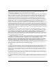
Configuring application settings Figure 80 VLAN Configuration: MAC SA Based setting page Table 68 describes the items on the VLAN Configuration: MAC SA Based setting page. Table 68 VLAN Configuration: MAC SA Based setting page items Item Range Description VLAN 1..4094 Type a unique number to identify the VLAN. VLAN Name 1..16 Type a unique name to identify the VLAN, for example *. Learning Constraint (1) IVL (2) SVL (default) Choose your learning constraint type.
Configuring application settings 4 Type information in the text boxes, or select from a list. 5 Do one of the following: • • 185 Click Submit. Click Back to return to the VLAN Configuration page without making changes. The new MAC SA-based VLAN configuration appears in the VLAN Table on the VLAN Configuration page (Figure 75). Modifying a MAC SA-based VLAN To modify an existing MAC SA-based VLAN: 1 From the main menu, choose Application > VLAN > VLAN Configuration.
Configuring application settings Table 69 describes the items on the VLAN Configuration: MAC SA Based modification page. Table 69 VLAN Configuration: MAC SA Based modification page items Item Description VLAN The number assigned to the VLAN when the VLAN was created. VLAN Name (Re)name the VLAN. Opens the VLAN Configuration: MAC Address page (Figure 82). Learning Constraint The type of learning constraint selected when the VLAN was created. The learning constraint choices are IVL and SVL.
Configuring application settings 5 187 In the MAC Address Creation section, type the MAC address to associate with the VLAN. The MAC address appears in the MAC Address Table (Figure 82). Note: You can delete an existing MAC address by clicking the delete icon in the row of the MAC address you want to delete. 6 Do one of the following: • • 7 Click Submit to save your changes and return to the VLAN Configuration: MAC SA Based setting page.
Configuring application settings Deleting a VLAN configuration To delete a VLAN configuration: 1 From the main menu, choose Application > VLAN > VLAN Configuration. The VLAN Configuration page opens (Figure 75). 2 In the VLAN Table, click the Delete icon for the entry you want to delete. A message opens prompting you to confirm your request. 3 Do one of the following: • • Click Yes to delete the VLAN configuration. Click Cancel to return to the VLAN Configuration page without making changes.
Configuring application settings 189 Figure 83 Port Configuration page Table 70 describes the items on the Port Configuration page. Table 70 Port Configuration page items Item Range Description Port 1..28 The port number. Port Name 1..16 Type character string to create a unique port name, for example, Unit 1, Port 1. Filter Tagged Frames (1) Yes (2) No Choose how to process filter tagged frames. When a flag is set (Yes), the frames are discarded by the forwarding process.
Configuring application settings Table 70 Port Configuration page items (continued) Item Range Description PVID 1..4094 Type the number of the VLAN ID to assign to untagged frames received on this trunk port. For example, a port with a PVID of 3 assigns all untagged frames received on this port to VLAN 3. The default setting is 1. Note: If AutoPVID is enabled and you want another PVID, enter the desired PVID here. Port Priority 0-7 Choose the level of priority for each port.
Configuring application settings 191 Figure 84 Port Information page Table 71 describes the items on the Port Information page. Table 71 Port Information page items Section Item Range Description VLAN Port Information (View By) Unit 1..8 Choose the number of the switch to view. Port 1..28 VLAN Port Information Table Choose the number of the switch’s port to view. PVID The PVID assigned when the VLAN port was created. Port Name The port name assigned when the VLAN port was created.
Configuring application settings Managing spanning tree groups You can configure system parameters for Spanning Tree Protocol, the industry standard for avoiding loops in switched networks. You can configure individual switch ports or all switch ports for participation in the spanning tree algorithm (STA). Note: STP resolves duplicate paths in networks and is not necessary for ports that have workstations directly attached to the switch.
Configuring application settings 193 Beginning with software version 2.0, you can set the spanning tree priority and path cost for each individual port. Creating spanning tree groups To configure spanning tree groups: 1 From the main menu, choose Application > Spanning Tree > Group Configuration. The Group Configuration page opens (Figure 85). Figure 85 Spanning Tree Group Configuration page Table 72 describes the items on the Spanning Tree Group Configuration page.
Configuring application settings Table 72 Spanning Tree Group Configuration page items Section STP Group Creation 209570-C Item Description Bridge Priority For the STP Group, indicates the management-assigned priority value of the bridge ID in hexadecimal notation, which is the most significant byte of the bridge ID. The spanning tree algorithm uses this parameter to determine the root bridge (or designated bridge).
Configuring application settings 2 Complete the fields as shown. 3 Click Submit. 195 Associating STG with VLAN membership To add a VLAN to an STG: 1 From the main menu, choose, Application > Spanning Tree > VLAN Membership. The Spanning Tree VLAN Membership page opens (Figure 86). Figure 86 Spanning Tree VLAN Membership page The table displays the spanning tree group and the current VLAN membership. You can add or remove one or more VLANs to an STG. Note: Beginning with software version 2.
Configuring application settings The Spanning Tree VLAN Membership Add VLAN page opens (Figure 87). Figure 87 Spanning Tree Add VLAN page 3 b Enter the number of the VLAN(s) you want to add to the STG. c Click Submit. To remove a VLAN: a Click the modification icon in the Remove VLAN column. The Spanning Tree VLAN Membership Remove VLAN page opens (Figure 88). Figure 88 Spanning Tree Remove VLAN page 209570-C b Enter the number of the VLAN(s) you want to remove to the STG. c Click Submit.
Configuring application settings 197 Note: You cannot delete VLAN 1 from STG 1. Configuring ports for spanning tree To configure switch ports for Spanning Tree participation: 1 From the main menu, choose Application > Spanning Tree > Port Configuration. The Spanning Tree Port Configuration page opens (Figure 89). Figure 89 Spanning Tree Port Configuration page Using Web-based Management for the Business Policy Switch 2000 Software Version 2.
Configuring application settings Table 73 describes the items on the Spanning Tree Port Configuration page. Table 73 Spanning Tree Port Configuration page items Section Item Description STP Group Group Choose the STG Group you want to view. Spanning Tree - Port Port Setting The port number of the currently displayed unit. Trunk The trunk that corresponds to the switch ports specified as MLT members. Tagging Displays whether the port is a tagged or an untagged port.
Configuring application settings 199 Changing spanning tree bridge switch settings You can view and configure existing Spanning Tree switch settings. To configure Spanning Tree switch settings: 1 From the main menu, choose Application > Spanning Tree > Bridge Information. The Spanning Tree Bridge Information page opens (Figure 90). Figure 90 Spanning Tree Bridge Information page Using Web-based Management for the Business Policy Switch 2000 Software Version 2.
Configuring application settings Table 74 describes the items on the Spanning Tree Bridge Information page. Table 74 Spanning Tree Bridge Information page items Section Item STP Group Group Spanning Tree - Bridge Bridge Priority Information Range Description Choose the STP Group you want to work with. 0..65535 Type the priority value of the bridge ID in hexadecimal notation, which is the most significant byte of the bridge ID.
Configuring application settings 201 Table 74 Spanning Tree Bridge Information page items Section Item Range Description Bridge Hello Time 1..10 seconds The Hello Interval (the amount of time between transmissions of BPDUs) specified by management for this bridge. This parameter takes effect only when this bridge becomes the root bridge.
Configuring application settings Configuring MultiLink Trunk (MLT) members You can configure groups of links between the BPS 2000 and another switch or a server to provide higher bandwidth with active redundant links. Trunked ports can span multiple units of the stack for fail-safe connectivity to mission-critical servers and the network center. You can configure two to four switch ports together as members of a trunk to a maximum of six trunks.
Configuring application settings 203 Figure 91 Group page Using Web-based Management for the Business Policy Switch 2000 Software Version 2.
Configuring application settings Table 75 describes the items on the Group page. Table 75 Group page items Section Item Range Description MultiLink Trunk Group Setting Trunk 1..6 This column contains fields in each row that can be configured to create the corresponding trunk. The Unit value in the (Unit/Port) field is configurable only when the switch (unit) is part of a stack configuration.
Configuring application settings 205 Monitoring MLT traffic You can monitor the bandwidth usage for the MultiLink Trunk member ports within each trunk in your configuration by selecting the traffic type to monitor. To monitor MultiLink Trunk traffic: 1 From the main menu, choose Application > MultiLink Trunk > Utilization. The Utilization page opens (Figure 92). Figure 92 Utilization page Table 76 describes the items on the Utilization page.
Configuring application settings Table 76 Utilization page items (continued) Section Item Range Description MultiLink Trunk Utilization Table Unit/Port A list of the trunk member switch ports that correspond to the trunk specified in the Trunk column. Last 5 Minutes% The percentage of packets (of the type specified in the Traffic Type field) used by the port in the last five minutes. This field provides a running average of network activity, and is updated every 15 seconds.
Chapter 8 Implementing QoS Using QoS Wizard and QoS Quick Config You can configure Quality of Service (QoS) features in your network by using the Web-based QoS Wizard, using the QoS Quick Config pages, or using the Advanced QoS configuration pages available in the Web-based management user interface. This chapter shows how to use the QoS Wizard and QoS Quick Config pages to configure QoS parameters for the BPS 2000.
Implementing QoS Using QoS Wizard and QoS Quick Config Using QoS Wizard The QoS Wizard provides a set of Web pages that allows you to specify common QoS settings for the BPS 2000. Warning: Nortel Networks recommends that you use the QoS Wizard for your initial configuration only. Each time the QoS Wizard is initiated, all existing configurations are reset to the default values.
Implementing QoS Using QoS Wizard and QoS Quick Config 209 Figure 93 QoS Wizard opening page 2 To continue the configuration process, click Next. A packet prioritization selection page opens (Figure 94). Figure 94 Packet prioritization selection page 3 Select No. Using Web-based Management for the Business Policy Switch 2000 Software Version 2.
Implementing QoS Using QoS Wizard and QoS Quick Config 4 Click Next. A Standard prioritization page opens (Figure 95). Note: If you want to prioritize traffic, skip this step and continue the steps outlined in “Prioritizing traffic with the QoS Wizard.” T Figure 95 Standard prioritization page 5 To complete the configuration process, click Finish. The session confirmation page appears (Figure 96).
Implementing QoS Using QoS Wizard and QoS Quick Config 211 Using the QoS Wizard, you can prioritize traffic by one of these categories, by two categories, or by all three. Also, you can define more than one flow in each category. The QoS Wizard leads you through the following four general steps in defining each flow you want to prioritize: • Step 1 is setting the category of prioritized traffic flow—VLAN, IP Application, or User defined flow.
Implementing QoS Using QoS Wizard and QoS Quick Config Additionally, the packet prioritization screen has a Status button that displays a QoS Policies to Configure in a pop-up window (Figure 97). As you finish configuring each type of flow, this pop-up window displays with the configured flows you configure using the QoS Wizard listed. When you completely finish the QoS Wizard, the policies are implemented.
Implementing QoS Using QoS Wizard and QoS Quick Config 213 A packet prioritization selection page opens (Figure 94). 3 Select Yes. 4 Click Next. A packet prioritization explanation page opens (Figure 98). Figure 98 Packet prioritization explanation page a To see the policies you have configured, click Status. The QoS Policies to Configure table opens in a pop-up window (Figure 97).
Implementing QoS Using QoS Wizard and QoS Quick Config Figure 99 VLAN prioritization selection page 2 Choose the VLAN and click Next. A page opens (Figure 100) that asks if you want to set a Meter for the specified VLAN. Figure 100 Meter for VLAN page 3 If you do not want to set a Meter, click No. The system opens to the Service Class selection page (Figure 102), which appears with only one Service Class to set. You do not have In-Profile and Out-of-Profile without metering data.
Implementing QoS Using QoS Wizard and QoS Quick Config 215 Figure 101 Meter setting for VLAN page 5 Enter the committed rate you want for this Meter. 6 Enter the expected burst rate you want for this Meter. The system calculates a series of 7 or fewer possible durations for the committed and expected burst rates you set. 7 Choose the Duration you want. 8 Click Next.
Implementing QoS Using QoS Wizard and QoS Quick Config Figure 102 Service Class selection for VLAN page 9 Click either Service Class or Drop. If you click Service Class, choose the Service Class you want from the pull-down menu. If you click Drop, the traffic in the specified VLAN is dropped. 10 Click Next. A page opens (Figure 103) that allows you to set shaping criteria for the specified VLAN.
Implementing QoS Using QoS Wizard and QoS Quick Config 217 Figure 103 Shaper for VLAN page 11 If you do not want to shape traffic for the specified VLAN, click No. The system opens to a page (Figure 105) that asks you if you want to prioritize traffic for another VLAN. If you fill the resources of the QoS Wizard, you will not be prompted for another VLAN. 12 If you want to shape traffic for the specified VLAN, click Yes.
Implementing QoS Using QoS Wizard and QoS Quick Config Figure 104 Setting shaping parameters for VLAN page 13 Enter the shaping rate you want for this Shaper. The system rounds up shaping rates you enter, including 0, to multiples of 64 Kbps. 14 Enter the maximum burst rate you want for this Shaper. The system calculates a series of 6 or fewer possible durations for the shaping and maximum burst rates you set. 15 Choose the Maximum Burst Duration from the pull-down menu.
Implementing QoS Using QoS Wizard and QoS Quick Config 219 Figure 105 Additional VLANs page 18 If you want to prioritize traffic for another VLAN, click Yes and Next. The system returns you to the VLAN prioritization page (Figure 99), and you continue through steps 1 to 17 for the next VLAN. 19 If you do not want to prioritize traffic for another VLAN, click No and Next. The system returns you to the packet prioritization page (Figure 106), with a check mark next to VLAN,.
Implementing QoS Using QoS Wizard and QoS Quick Config Figure 106 Packet prioritization page with prioritized VLAN(s) Figure 107 QoS Policies to Configure window with VLAN entry 20 When you are through with the table, click Back, then click Submit. You will see a session confirmation page. Prioritizing IP applications with the QoS Wizard You can specify that different IP applications in your network configuration are marked with different priority levels.
Implementing QoS Using QoS Wizard and QoS Quick Config 221 Figure 108 IP Application prioritization page 2 Click the application(s) you want to prioritize and click Next. A page opens (Figure 109) that asks if you want to set a Meter for the specified IP Application. Figure 109 Meter for IP Application page 3 If you do not want to set a Meter, click No. The system opens to the Service Class selection page (Figure 111), which appears with only one Service Class to set.
Implementing QoS Using QoS Wizard and QoS Quick Config A page opens (Figure 110) that allows you to set a Meter for the specified IP Application. Figure 110 Meter setting for IP Application page 5 Enter the committed rate you want for this Meter. 6 Enter the expected burst rate you want for this Meter. The system calculates a series of 7 or fewer possible durations for the committed and expected burst rates you set. 7 Choose the Duration you want. 8 Click Next.
Implementing QoS Using QoS Wizard and QoS Quick Config 223 Figure 111 Service Class selection for IP Application page 9 Click either Service Class or Drop. If you click Service Class, choose the Service Class you want from the pull-down menu. If you click Drop, the traffic in the specified IP Application is dropped. 10 Click Next. A page opens (Figure 112) that allows you to set shaping criteria for the specified IP Application.
Implementing QoS Using QoS Wizard and QoS Quick Config Figure 112 Shaper for IP Application page 11 If you do not want to shape traffic for the specified IP Application, click No. a If you chose more than one IP Application to prioritize, a page opens that asks if you want to set a Meter for the next specified IP Application (Figure 109). Repeat steps 3 through 17 for each IP Application you chose.
Implementing QoS Using QoS Wizard and QoS Quick Config 225 Figure 113 Setting shaping parameters for IP Application page 13 Enter the shaping rate you want for this Shaper. The system rounds up shaping rates you enter, including 0, to multiples of 64 Kbps. 14 Enter the maximum burst rate you want for this Shaper. The system calculates a series of 6 or fewer possible durations for the shaping and maximum burst rates you set. 15 Choose the Maximum Burst Duration from the pull-down menu.
Implementing QoS Using QoS Wizard and QoS Quick Config If you fill the resources of the QoS Wizard, you will not be prompted for another IP Application. Figure 114 Packet prioritization page with prioritized IP Application(s) Figure 115 QoS Policies to Configure window with IP Application entry 18 When you are through viewing the table, click Back, then Submit. You see a session confirmation page.
Implementing QoS Using QoS Wizard and QoS Quick Config 227 Figure 116 Policy label page 2 Enter the name of the flow and click Next. A page opens (Figure 117) that asks if you want to set an IP filter or a layer 2 filter. Figure 117 Policy definition page a If you want an IP filter, click IP Filter and click Next. A page opens that requests the customer to choose the IP filter criteria for the specified flow (Figure 118 and Figure 119).
Implementing QoS Using QoS Wizard and QoS Quick Config Figure 118 IP classification rules page (1 of 2) Figure 119 IP classification rules page (2 of 2) 209570-C
Implementing QoS Using QoS Wizard and QoS Quick Config 229 — Choose the IP filter parameters you want the flow to have. (Refer to Chapter 9 for a description of the parameters.) — Click Next. A page opens (Figure 122) that asks if you want to set a Meter for the specified flow. b If you want a layer 2 filter, click Layer2 Filter and click Next. A page opens that requests the customer to choose the layer 2 filter criteria for the specified flow (Figure 120 and Figure 121).
Implementing QoS Using QoS Wizard and QoS Quick Config Figure 121 Layer 2 classification rules page (2 of 2) — Choose the layer 2 filter parameters you want the flow to have. (Refer to Chapter 9 for a description of the parameters.) Beginning with software version 2.0, you can reference up to 32 VLANs with a single layer 2 filter. — Click Next. A page opens (Figure 122) that asks if you want to set a Meter for the specified flow.
Implementing QoS Using QoS Wizard and QoS Quick Config 231 Figure 122 Meter for user defined flow page 3 If you do not want to set a Meter, click No. The system opens to the Service Class selection page (Figure 124), which appears with only one Service Class to set. You do not have In-Profile and Out-of-Profile without metering data. 4 If you want to set a Meter, click Yes. A page opens (Figure 123) that allows you to set a Meter for the specified flow.
Implementing QoS Using QoS Wizard and QoS Quick Config 6 Enter the expected burst rate you want for this Meter. The system calculates a series of 7 or fewer possible durations for the committed and expected burst rates you set. 7 Choose the Duration you want. 8 Click Next. A page opens (Figure 124) that allows you to select a Service Class separately for both the In-Profile and Out-of-Profile Action for the specified flow.
Implementing QoS Using QoS Wizard and QoS Quick Config 233 Note: You must be using either the BPS2000-1GT, BPS2000-2GT, or BPS2000-2GE MDA with the Business Policy Switch in order to implement the QoS shaping features. Figure 125 Shaper for user defined flow page 11 If you do not want to shape traffic for the specified flow, click No. A page opens (Figure 127) that asks if you want to prioritize traffic for another user defined flow. 12 If you want to shape traffic for the specified flow, click Yes.
Implementing QoS Using QoS Wizard and QoS Quick Config Figure 126 Setting shaping parameters for user defined flow page 13 Enter the shaping rate you want for this Shaper. The system rounds up shaping rates you enter, including 0, to multiples of 64 Kbps. 14 Enter the maximum burst rate you want for this Shaper. The system calculates a series of 6 or fewer possible durations for the shaping and maximum burst rates you set. 15 Choose the Maximum Burst Duration from the pull-down menu.
Implementing QoS Using QoS Wizard and QoS Quick Config 235 Figure 127 Additional user defined flows page 17 If you want to prioritize traffic for another user defined flow, click Yes and Next. The system returns you to the policy label page (Figure 116), and you continue through steps 1 to 17 for the next user defined flow. If you fill the resources of the QoS Wizard, you will not be prompted for another user defined flow.
Implementing QoS Using QoS Wizard and QoS Quick Config Figure 128 Packet prioritization page with prioritized User Defined Flow(s) Figure 129 QoS Policies to Configure window with user defined flow entry 19 When you are through viewing the table, click Back and then Submit. You see a session confirmation page. Using QoS Quick Config This section describes how to use the QoS Quick Config option to configure QoS parameters for the BPS 2000.
Implementing QoS Using QoS Wizard and QoS Quick Config 237 The QoS Quick Config option provides a set of Web pages for configuring QoS parameters. Using the QoS Quick Config does not reset the QoS parameters to default values as the QoS Wizard does. The QoS Quick Config condenses the QoS Advanced pages to just two pages and uses only default actions and mappings.
Implementing QoS Using QoS Wizard and QoS Quick Config — Interface Class Refer to Using the Business Policy Switch 2000 Software Version 2.0 for more information on interface classes. — Port Membership 3 To create an Interface Group, click Create Interface Group. The QoS Quick Config Interface Group page opens (Figure 131) with the Create Interface Groups option displaying.
Implementing QoS Using QoS Wizard and QoS Quick Config 239 Figure 132 QoS Quick Config Interface Group page—View Interface Group 8 Go to “Using QoS Quick Config to configure policies,” next. Using QoS Quick Config to configure policies You use QoS Quick Config Web pages to configure the policies. To configure QoS policies using QoS Quick Config: ➨ From the main menu, choose Application > QoS > QoS Quick Config > Policy. The QoS Quick Config Policy page opens (Figure 133, Figure 134, and Figure 135).
Implementing QoS Using QoS Wizard and QoS Quick Config Figure 133 QoS Quick Config Policy page (1 of 3) Figure 134 QoS Quick Config Policy page (2 of 3) 209570-C
Implementing QoS Using QoS Wizard and QoS Quick Config 241 Figure 135 QoS Quick Config Policy page (3 of 3) The QoS Quick Config Policy page contains the following four steps: • • • • Step 1: Rule Step 2: Meter Step 3: Shaper Step 4: Policy This section discusses the following areas: • • • • • “Configuring QoS Quick Config filters,” next “Deleting Qos Quick Config filters from the filter group” on page 246 “Configuring QoS Quick Config meters” on page 247 “Configuring QoS Quick Config shapers” on page
Implementing QoS Using QoS Wizard and QoS Quick Config Figure 136 QoS Quick Config page for configuring IP filters page (1 of 2) Figure 137 QoS Quick Config page for configuring IP filters page (2 of 2) 2 209570-C Enter the number you want for the order of the IP filter you are configuring.
Implementing QoS Using QoS Wizard and QoS Quick Config 3 243 Complete the Destination Address/Mask area by either: — choosing Ignore — entering the Network Address, Subnet Mask, and Host Address 4 Complete the Source Address/Mask area by either: — choosing Ignore — entering the Network Address, Subnet Mask, and Host Address 5 In the DSCP field, choose either Ignore or a value from the pull-down menu. 6 In the IP Protocol field, choose either Ignore or a protocol from the pull-down menu.
Implementing QoS Using QoS Wizard and QoS Quick Config Figure 138 QoS Quick Config page for configuring layer 2 filters page (1 of 2) Figure 139 QoS Quick Config page for configuring layer 2 filters page (2 of 2) 209570-C 2 Enter the number you want for the order of the layer 2 filter you are configuring. 3 In the VLAN area, choose the VLANs you want from the pull-down menu.
Implementing QoS Using QoS Wizard and QoS Quick Config 245 Note: Beginning with software version 2.0, you can reference up to 32 VLANs with a layer 2 filter. 4 In the VLAN Tag area, choose either Ignore, Tagged, or Untagged from the pull-down menu. 5 Complete the EtherType area by either: — choosing Ignore — choosing a preconfigured Ethernet type from the pull-down menu — entering a hex value for the User Defined Ethernet type 6 Complete the 802.
Implementing QoS Using QoS Wizard and QoS Quick Config 1 Click Using Existing Filter Group. A page opens that displays the Using Existing Filter Group option checked (Figure 140). Figure 140 QoS Quick Config page with existing filter group choice 2 Go to “Configuring QoS Quick Config meters” on page 247.
Implementing QoS Using QoS Wizard and QoS Quick Config 247 Figure 141 QoS Quick Config Policy page with displayed filter group 2 To delete the filter from the filter group, click the X icon at the far left of the table. Configuring QoS Quick Config meters Using Step 2: Meters, you choose to use nonmetered data for specified flow, to configure a new meter for the flow, or to use an existing meter for the flow. To choose no metered data for the flow: 1 Click No Meter.
Implementing QoS Using QoS Wizard and QoS Quick Config Figure 142 QoS Quick Config Policy page with expanded meter area 2 Enter the name you want for the meter in the Meter Name field. 3 In the Committed Rate field, enter the rate you want for your meter. 4 In the Committed Burst Size field — Enter the burst you want to allow — Choose among the 6 or fewer durations the system calculates for the meter. 5 Go to “Configuring QoS Quick Config shapers” on page 248.
Implementing QoS Using QoS Wizard and QoS Quick Config 249 To choose not to shape the data for the flow: 1 Click No Shaper. 2 Go to “Configuring QoS Quick Config policies” on page 250. To configure a new shaper: 1 Click Configure Shaper, under Step 3: Shaper (Figure 143). Figure 143 Step 3: Shaper The Shaper box opens (Figure 144). Figure 144 Shaper box 2 Enter the name for the shaper you are configuring in the Shaper Name field. 3 In the Rate field, enter the committed rate you want in Kbps.
Implementing QoS Using QoS Wizard and QoS Quick Config 6 Choose the queue size from the pull-down menu in the Queue Size field. The queue size is the amount to traffic that can exceed the maximum burst size and still be queued for transmission. This traffic is delayed for shaping purposes. 7 Go to “Configuring QoS Quick Config policies” on page 250. To use an existing shaper for the flow: 1 Click Use Existing Shaper, under Step 3: Shaper (Figure 143).
Implementing QoS Using QoS Wizard and QoS Quick Config 251 Figure 145 Policy area of QoS Quick Config Policy page 1 In the Policy Name field, enter a character string to assign a name for the policy you are configuring. 2 In the Policy Order field, enter the value you want for the evaluation order of the policy you are configuring. 3 In the Role Combination field, choose the Role Combination you want.
Implementing QoS Using QoS Wizard and QoS Quick Config Figure 146 QoS Advanced Policies page with configured policies (1 of 2) Figure 147 QoS Advanced Policies page with configured policies (2 of 2) 209570-C
Chapter 9 Implementing QoS using QoS Advanced The QoS application delivers a set of tools that, when optimally configured, combats escalating bandwidth costs and optimizes application performance in your network. QoS tools allow you to prioritize your critical applications and sensitive traffic. You can tailor appropriate services to support this traffic over the wide area, thus maintaining the necessary performance levels on an end-to-end basis.
Implementing QoS using QoS Advanced • • • “Configuring QoS shapers” on page 294 “Configuring QoS policies” on page 297 “Configuring QoS Policy Agent (QPA) characteristics” on page 304 Note: To configure the features introduced with software version 1.2 and higher in a mixed stack, you must access a BPS 2000 unit.
Implementing QoS using QoS Advanced 255 Figure 148 QoS Advanced Interface Configuration page Table 77 describes the items on the Interface Queue Table section of the QoS Advanced Interface Configuration page. Table 77 QoS Interface Queue Table section items Item Description Set ID The number that identifies a specific queue set. Queue ID The number that identifies the queue in the given set. General Discipline The queueing discipline that is associated with the specified queue.
Implementing QoS using QoS Advanced Table 78 describes the items on the Interface Group Table section of the QoS Advanced Interface Group page. Table 78 Interface Group Table section items Item Description Opens a modification page. Deletes the row. Role Combination The tag used to identify interfaces with the characteristics specified by the attributes of this class instance (string 1..64).
Implementing QoS using QoS Advanced 257 Table 79 describes the items on the Interface Group Creation section of the QoS Advanced Interface Group page. Table 79 Interface Group Creation section page items Item and MIB association Range Description Role Combination (qosInterfaceTypeRoles) 1..64 Type a character string to identify the role combination.
Implementing QoS using QoS Advanced The table displays all created interface groups, whether created using the Qos Advanced pages, the QoS Wizard, or the QoS Quick config. Figure 149 Interface ID page Table 81 describes the items on the Interface ID page. Table 80 Interface ID page items Item Description Interface Displays the unit and port number. Role Combination Displays the role combination associated with the interface. Queue Sets Displays the queue set associated with this interface.
Implementing QoS using QoS Advanced 2 259 In the Interface Group Table section, in the row of your choice, click the Modify icon. The Interface Group Assignment page opens (Figure 150). Figure 150 Interface Group Assignment page Table 81 describes the items on the Interface Group Assignment page. Table 81 Interface Group Assignment page items Item Description Role Combination The tag used to identify interfaces with the characteristics specified by the attributes of this class instance (string 1..
Implementing QoS using QoS Advanced Note: Beginning with software version 2.0, you can add all ports of one unit simultaneously, by clicking All. Also, if you are using stacked BPS 2000, you can modify, add, or delete the interfaces of only one unit at a time. 4 Do one of the following: • • Click Submit. Click Back to return to the Interface Configuration page without making changes.
Implementing QoS using QoS Advanced 5 261 In the Interface Group Table section, in the configuration row of your choice, click the Delete icon. A message opens prompting you to confirm your request. 6 Do one of the following: • • Click Yes to delete the interface group configuration. Click Cancel to return to the Interface Configuration page without making changes. Configuring 802.1p priority queue assignment Note: Nortel Networks recommends using the default 802.
Implementing QoS using QoS Advanced Figure 151 802.1p Priority Queue Assignment page Table 82 describes the items on the 802.1p Priority Queue Assignment page. Table 82 802.1p Priority Assignment Table section page items Section Item and MIB association Description 802.1p Priority Assignment (View By) Queue Set Choose the queue set you want to modify. 802.1p Priority Assignment Table 802.1p Priority (ntnQosIfPriAssignmentPri) The 802.1p user priority mapped to a queue.
Implementing QoS using QoS Advanced 5 263 Click Submit. Note: Clicking Submit in the 802.1p Priority Assignment Table section results in a system reset. Configuring 802.1p priority mapping Note: Nortel Networks recommends using the default 802.1p priority to DSCP mappings to ensure end-to-end QoS connectivity. To configure 802.1p priority to DSCP mapping: 1 From the main menu, choose Application > QoS > QoS Advanced > Devices > Priority Mapping. The 802.1p Priority Mapping page opens (Figure 152).
Implementing QoS using QoS Advanced Table 83 describes the items on the 802.1p Priority Mapping page. Table 83 802.1p Priority Mapping page items Item Description 802.1p Priority The 802.1p user priority to map to a DSCP value at ingress. DSCP Type the DSCP value to associate with the specified 802.1p user priority value at ingress. 2 Type the information in the text boxes. 3 Click Submit.
Implementing QoS using QoS Advanced 265 Table 84 describes the items on the DSCP Queue Assignment page. Table 84 DSCP Queue Assignment page items Section Item Format DSCP Assignment (View By) Queue Set Choose the queue set to display in the DSCP Assignment Table. DSCP Assignment Table DSCP The DSCP value to map to a queue. Queue The queue set to which the traffic with the given DSCP value is associated.
Implementing QoS using QoS Advanced Figure 154 DSCP Mapping Table page Table 85 describes the items on the DSCP Mapping Table page. Table 85 DSCP Mapping Table page items Item Format Opens a modification page. DSCP The attribute used internally to determine the appropriate Layer 2 cost of service (CoS) mappings. 802.1p Priority The IEEE802 CoS value used when mapping the DSCP value specified by the qos802DscpMappingDscp attribute to an IEEE 802 CoS.
Implementing QoS using QoS Advanced 2 267 In the row of your choice, click the Modification icon. The DSCP Mapping Modification page opens (Figure 155). Figure 155 DSCP Mapping Modification page Table 86 describes the items on the DSCP Mapping Modification page. Table 86 DSCP Mapping Modification page items Item Range Format DSCP 0..63 Type the attribute to use internally to determine the appropriate Layer 2 cost of service (CoS) mappings. 802.1p Priority 0..
Implementing QoS using QoS Advanced 3 Select from a list. 4 Click Submit. The modified configuration appears in the DSCP Mapping Table (Figure 154). Note: For more information on QoS interface classes—or trusted, untrusted, and unrestricted ports—refer to Using the Business Policy Switch 2000 Software Version 2.0. IP filter and IP filter group configurations You can create an IP filter, which enables the switch to classify traffic.
Implementing QoS using QoS Advanced 269 Figure 157 IP Classification page (2 of 3) Figure 158 IP Classification page (3 of 3) Note: When you choose the Ignore value, the filter matches all criteria for that parameter. Using Web-based Management for the Business Policy Switch 2000 Software Version 2.
Implementing QoS using QoS Advanced Table 87 describes the items on the IP Filter Table and IP Filter Creation sections of the IP Classification page. Table 87 IP Filter Table and Filter Creation sections page items Section Item and MIB association IP Filter Table Action Range Description Deletes the row. Note: You cannot delete a filter if it is referenced in a filter group. Instance IP Filter Creation/ Destination Address 209570-C Displays unique identifier.
Implementing QoS using QoS Advanced 271 Table 87 IP Filter Table and Filter Creation sections page items (continued) Item and MIB association Section Host Address) IP Filter Creation/ Source Address Range Description XXX.XXX.XXX. XXX Click if you want the filter to match the packet’s destination host IP address. Enter the IP address to match against the packet’s destination IP address. Ignore Click if you want the filter to ignore the packet’s source IP address. Network Address XXX.XXX.XXX.
Implementing QoS using QoS Advanced 2 In the IP Filter Creation section, type information in the text boxes, or select from a list. 3 Click Submit. The new IP filter configuration appears in the IP Filter Table (Figure 156). This table displays all IP filters you created, using QoS wizard, Qos Quick Config, or QoS Advanced pages. Note: An IP filter configuration is not modifiable. The filter must be deleted and then re-created.
Implementing QoS using QoS Advanced 1 273 From the main menu, choose Application > QoS > QoS Advanced > Rules > IP Classification. The IP Classification page opens (Figure 156). Table 88 describes the items on the IP Filter Group section of the IP Classification page. Table 88 IP Filter Group section page items Item Description Opens a modification page. Deletes the row. Filter Group Name A list of existing filter group configurations. Opens a filter group creation page.
Implementing QoS using QoS Advanced Figure 159 IP Classification Group page Table 89 describes the items on the IP Classification Group page. Table 89 IP Classification Group page items Item Range Description Filter Group Name 1..16 Enter a character string to create an identity for the filter group configuration. Group Order Select (or deselect) the filter from membership in the filter group. Integer Type a number to establish the evaluation order of filters in the group.
Implementing QoS using QoS Advanced 275 Table 89 IP Classification Group page items Item Range Source L4 Port Description The value that the packet’s layer 4 source port number can have and match the filter entry. Permit (1) True (2) False If the frame matches the filter when this is set to true, the matching process stops. Note: To group multiple filters in a single group, assign Filter Index and Filter Order the same filter group name.
Implementing QoS using QoS Advanced The IP Group Modification page opens (Figure ). This table displays all IP filter you created, using QoS wizard, Qos Quick Config, or QoS Advanced pages. IP Group Modification page Table 90 describes the items on the IP Group Modification page. Table 90 IP Modification Group page items Item Range Description Filter Group Name 1..16 Displays the name of the selected the filter group. Integer Displays the order for existing groups.
Implementing QoS using QoS Advanced 277 Table 90 IP Modification Group page items Item Range Description Permit (1) True (2) False If the frame matches the filter when this is set to true, the matching process stops. Note: To group multiple filters in a single group, assign Filter Index and Filter Order the same filter group name. 3 Select (or deselect) the filter as a member of the Filter Group. 4 Click Submit.
Implementing QoS using QoS Advanced Layer 2 filter and layer 2 filter group configurations You can configure layer 2 filters by defining IEEE 802-based parameters, and selective layer 3 and layer 4 parameters. Layer 2 filter groups are defined by specifying the layer 2 filter to be included in the given filter group. Beginning with software version 2.0, you can match up to 32 VLANs in one layer 2 filter.
Implementing QoS using QoS Advanced 279 Figure 161 Layer2 Classification page (2 of 2) Table 91 describes the items on the Layer2 Filter Table and Layer2 Filter Creation sections of the Layer2 Classification page. Table 91 Layer2 Filter Table and Layer2 Filter Creation section items Section Item Range Description Layer 2 Filter Table Action Deletes the row. Instance Displays unique identifier. VLAN Ignore, 1-32 Click the VLANs you want to reference with this filer, up to 32 VLANs.
Implementing QoS using QoS Advanced Table 91 Layer2 Filter Table and Layer2 Filter Creation section items (continued) Section 209570-C Item Range Description EtherType Ignore Displays the EtherType to match.
Implementing QoS using QoS Advanced 281 Table 91 Layer2 Filter Table and Layer2 Filter Creation section items (continued) Section Layer2 Filter Creation Item Range Description IP Protocol Ignore TCP UDP ICMP IGMP RSVP Displays the IP protocol to match against the packet’s IP protocol field. Destination IP L4 Port Min Ignore, Integer (0.65535) Displays the least value that the packet’s layer 4 destination port number can have and match this filter. Destination IP L4 Port Max Ignore, Integer (0.
Implementing QoS using QoS Advanced Table 91 Layer2 Filter Table and Layer2 Filter Creation section items (continued) Section 209570-C Item Range Description EtherType Ignore Choose the EtherType to match. Netmap TCP Netmap XNS XTP LOOP Vines Vines IP Banyan Vines Echo Vines Banyon Echo ARP RARP Note: If you choose User Defined, enter the value.
Implementing QoS using QoS Advanced 283 Table 91 Layer2 Filter Table and Layer2 Filter Creation section items (continued) Section Item Range Description IP Protocol Ignore TCP UDP ICMP IGMP RSVP Select the IP protocol to match against the packet’s IP protocol field. Destination IP L4 Port Range Ignore, Min, Max Choose Ignore or type the minimum value and the maximum value that the packet’s layer 4 destination port number can have and match this filter.
Implementing QoS using QoS Advanced 2 In the Layer2 Filter Table, in the layer 2 filter configuration row of your choice, click the Delete icon. A message opens prompting you to confirm your request. 3 Do one of the following: • • Click Yes to delete the filter configuration. Click Cancel to return to the Layer2 Classification page without making changes. Note: A Layer 2 filter configuration cannot be modified. The configuration must be deleted and then recreated.
Implementing QoS using QoS Advanced 2 285 Click Create Filter Group. The Layer2 Group page opens (Figure 162). Figure 162 Layer2 Group page Table 93 describes the items on the Layer2 Group page. Table 93 Layer2 Group page items Item Range Description Filter Group Name 1..16 Enter a character string to create an identity for the filter group configuration. Group Select (or deselect) the filter from membership in the filter group.
Implementing QoS using QoS Advanced Table 93 Layer2 Group page items Item Range Source L4 Port Max Description The maximum value that the packet’s layer 4 source port number can have and match this filter. Note: To group multiple filters in a single group, assign Filter Index and Filter Order the same filter group name. 3 Type information in the text boxes, or click the check box. 4 Click Submit. The new layer 2 filter group configuration appears in the Layer 2 Filter Group Table (Figure 160).
Implementing QoS using QoS Advanced 287 Table 94 describes the items on the Layer2 Group modification page. Table 94 Layer2 Group modification page items Item Range Description Filter Group Name 1..16 Displays the filter group name. Group Select (or deselect) the filter from membership in the filter group. Order Integer Enter a number to establish the evaluation order of filters in the group. Instance Displays a unique identifier. Filter ID Displays the filter identifier.
Implementing QoS using QoS Advanced 2 In the Layer2 Filter Group Table section, in the layer 2 filter group configuration row of your choice, click the Delete icon. A message opens prompting you to confirm your request. 3 Do one of the following: • • Click Yes to delete the filter group configuration. Click Cancel to return to the Layer2 Classification page without making changes. Note: You cannot delete a filter group that is referenced by a policy. You must first delete the policy.
Implementing QoS using QoS Advanced 289 Figure 164 Action page Table 95 describes the items on the Action page. Table 95 Action page items Item and MIB association Range Description Deletes the row. Action Name 1..16 Instance Type a character string to uniquely identify the action configuration. Displays the unique identifier. Transmit/Drop Frame (qosActionDrop) (1) Transmit (2) Drop Choose whether the frame being evaluated should be dropped or transmitted by this attribute.
Implementing QoS using QoS Advanced Table 95 Action page items (continued) Item and MIB association Range Description Set Drop Precedence (ntnQosActionExtSetDropPrec) (1) Ignore (2) Loss Sensitive (3) Not loss Sensitive (4) Use Defaults (5) Use Egress Map Choose a packet drop precedence value.
Implementing QoS using QoS Advanced • • 291 Click Yes to delete the filter configuration. Click Cancel to return to the Action page without making changes. Note: You cannot delete an action that is referenced by a meter. you must first delete the meter. Configuring QoS meters Using the QoS Advanced pages, you can create, view, or delete meters. If you do not want to meter the data in your flow, go to “Configuring QoS shapers” on page 294.
Implementing QoS using QoS Advanced Figure 165 QoS Advanced Meter page 2 In the Meter Creation area, create the meter. Table 96 describes the fields in the Meter Creation area, which you use to set new meters. Table 96 Meter Creation fields Item Range Description Name 1 to 16 alphanumeric characters with no spaces Enter the name for the meter you are creating. Committed Rate 13 - 1,700,000 Kbps Enter the Committed Rate in Kbps here.
Implementing QoS using QoS Advanced 4 293 If you have not already specified the interface assignments, choose Applications > QoS > QoS Advanced > Devices > Interface Configuration page to connect the desired ports to the desired filters. Note: Meter configurations are not modifiable. They must be deleted and the information re-entered. Viewing meters To view a meter: 1 From the main menu, choose Application > QoS > QoS Advanced > Meters. The QoS Advanced Meters page opens (Figure 165).
Implementing QoS using QoS Advanced Deleting a meter To delete a meter: 1 From the main menu, choose Application > QoS > QoS Advanced > Meters. The Meter page opens (Figure 165). 2 In the Meter Table section, click the Delete icon to delete the meter. A message opens prompting you to confirm your request. 3 Do one of the following: • • Click Yes to delete the meter configuration. Click Cancel to return to the Meter page without making changes.
Implementing QoS using QoS Advanced 1 295 From the main menu, choose Application > QoS > QoS Advanced > Shapers. The Qos Advanced Shapers page opens (Figure 166). All Shapers, including those created using the QoS Wizard and Qos Quick Config pages, display on this page. Figure 166 QoS Advanced Shapers page 2 In the Shaper Creation area, create the shape. Table 96 describes the fields in the Shaper Creation area, which you use to set new shapers.
Implementing QoS using QoS Advanced Table 98 Shaper Creation fields (continued) Item Range Description Burst Size 6 durations Maximum Burst Rate—Enter the Maximum Burst Rate in Kbps. This determines the maximum traffic burst size that can be transmitted without a shaping delay. Duration—From the pull-down menu, choose 1 of the 6 durations for the period that the Maximum Burst Rate is allowed. Queue Size 1, 2, 4, 8, or 16 packets Choose the queue depth from the pull-down menu.
Implementing QoS using QoS Advanced 297 Table 99 Shaper Table fields (continued) Item Range Burst Size Description Displays the maximum traffic burst size that can be transmitted without a shaping delay. Calculated internally using the configured Maximum Burst Rate and Maximum Burst Duration. Queue Size 1, 2, 4, 8, or 16 packets Displays the number of packets that can exceed the traffic burst size and still be queued for transmission.
Implementing QoS using QoS Advanced If you want to meter your data, you must reference both an In-Profile action and an Out-Profile action. The In-Profile action directs the switch how to handle the data flow that is within the meter you set (refer to “Configuring QoS meters”), and the Out-Profile directs the switch how to handle all other data. Installing defined filters To create a hardware policy filter configuration: 1 From the main menu, choose Application > QoS > QoS Advanced > Policies.
Implementing QoS using QoS Advanced 299 Figure 168 QoS Advanced Policies page (2 of 3) Figure 169 QoS Advanced Policies page (3 of 3) Using Web-based Management for the Business Policy Switch 2000 Software Version 2.
Implementing QoS using QoS Advanced Table 100 describes the items on the QoS Advanced Policy page. Table 100 Policy page items Section Item and MIB association Policy Table Action Range Description Opens a view only statistics table. The table displays current filter statistics in bytes and packets. Deletes the row. State (1) Enabled (2) Disabled Enables or disables the policy. Policy Name 1..16 A list of the names of existing target configurations. Instance Displays the unique identifier.
Implementing QoS using QoS Advanced 301 Table 100 Policy page items Section Item and MIB association Range Description Filter Group Choose the filter group to associate with this policy. Role Combination (qosTargetInterfaceRoles) Choose the type of interface to which this policy applies, specified in terms of a role combination. Policy Order (qosTargetOrder) Integer Enter a number to use as a determinate of the order of precedence for this filter.
Implementing QoS using QoS Advanced 2 In the Policy Table section, in the filter group configuration of your choice, click the View icon. The Policy Statistics page opens (Figure 170). Figure 170 Policy Statistics page Table 101 describes the items on the Policy Statistics page. Table 101 Policy Statistics page items Item and MIB association Description Policy Name The name of the selected policy.
Implementing QoS using QoS Advanced 303 Table 101 Policy Statistics page items (continued) Item and MIB association Description Overflow In Profile Octets (ntnQosTargetStatsTotalIn ProfOverflowOctets) The number of times the associated ntnQosTargetStatsTotalInProfOctets counter overflowed. Out Profile Octets (ntnQosTargetStatsTotalO utProfOctets) The total number of out-of-profile octets associated with packet hits for this policy.
Implementing QoS using QoS Advanced Configuring QoS Policy Agent (QPA) characteristics You can configure QPA operational parameters. To open the Agent page: 1 From the main menu, choose Application > QoS > QoS Advanced > Agent. The Agent page opens (Figure 171 and Figure 172).
Implementing QoS using QoS Advanced 305 Figure 172 Agent page (2 of 2) Table 102 describes the items on the Agent page. Table 102 Agent page items Section Item and MIB association Range Description QoS Configuration QoS Policy Server Control Enabled Disabled Choose to enable or disable the QoS Policy server control. Note: Choosing to enable COPS disables local policy control. QoS Policy Agent State (ntnQosConfigQpaState) Running Initialized Disabled The current status of the policy agent.
Implementing QoS using QoS Advanced Table 102 Agent page items (continued) Section Policy Class Support Table Policy Device Identification Table 209570-C Item and MIB association Range Description Allow Packet Reordering (ntnQosConfigAllowPacket Reordering) (1) Yes (2) No Support for certain PHBs requires that packets within a flow not be reordered when transmitted. Choose: • Yes—Allows full flexibility of assigning packet to egress queue.
Chapter 10 Implementing Common Open Policy Services (COPS) Enabling COPS in your networks allows the policy server to: • • • Gather all relevant information. Make a decision based on your (as network administrator) set policies and network resources, Communicate that decision in the form of proper service to the appropriate group or client (bandwidth, ACLs, QoS). A solid COPS strategy is closely tied to Internet Protocol (IP) address management and network management.
Implementing Common Open Policy Services (COPS) Viewing COPS statistics and capabilities You can view a list of the capabilities of the COPS client to connect to a COPS server and view a table displaying the current status of all COPS server connections. To view COPS capabilities and statistics: 1 From the main menu, choose Application > COPS > Status. The Status page opens (Figure 173). Figure 173 Status page Table 103 describes the items on the Status page.
Implementing Common Open Policy Services (COPS) 309 Table 103 Status page items (continued) Section Item Descriptions COPS Current Table, cont. Type The indicator of the source of the COPS server information. Note: COPS servers can be configured by network management into copsClientServerConfigTable and appear in this entry with type copsServerStatic(1).
Implementing Common Open Policy Services (COPS) Table 103 Status page items (continued) Section Item Descriptions COPS Statistics Table, cont. TCP Connection Attempts The number of times that the COPS client attempted to open a TCP connection to the COPS server. Note: This value is valid only for client type 0. Note: This is a cumulative value and is not zeroed on new connections. TCP Connection Failures The number of times that the COPS client failed to open a TCP connection to the COPS server.
Implementing Common Open Policy Services (COPS) 311 Table 103 Status page items (continued) Section Item Descriptions COPS Statistics Table, cont. Bad Sends The total number of COPS packets that the client attempted to send to COPS servers marked for the selected client type that resulted in a transmit error. Note: This is a cumulative value and is not zeroed on new connections.
Implementing Common Open Policy Services (COPS) Figure 174 Configuration page Table 104 describes the items on the COPS Configuration Table section of the Configuration page. Table 104 COPS Configuration Table section items Section Item COPS Configuration Table Range Description Deletes the row. Address Type The type of address in copsClientServerConfigAddress. Address The IPv4, IPv6, or DNS address of the COPS server.
Implementing Common Open Policy Services (COPS) 313 Table 104 COPS Configuration Table section items (continued) Section Item Range Description COPS Configuration Table, cont. Auth Type The authentication mechanism for this COPS client to request when negotiating security at the start of a connection to a COPS server. TCP Port The TCP port number on the COPS server. Priority The level of priority assigned to the client.
Implementing Common Open Policy Services (COPS) Deleting a COPS client configuration To delete a COPS client configuration: 1 From the main menu, choose Application > COPS > Configuration. The Configuration page opens (Figure 174). 2 In the COPS Configuration Table, click the Delete icon for the entry you want to delete. A message opens prompting you to confirm your request. 3 Do one of the following: • • 209570-C Click Yes to delete the configuration.
Chapter 11 Support menu The customer support options available to you are: • • • • Help Release Notes Manuals Upgrade Using the online help option You can read information about management page functions in the online help menu embedded in the Web-based management interface. To open online help: 1 From the main menu, choose Support > Help or click the Help icon located in the upper right corner of any management page. The Online Help menu opens in a separate Web browser (Figure 175).
Support menu Figure 175 Online help window 2 Click on any content item to read information about the topic (if you clicked the Help icon on a management page, information about that page is immediately displayed). 3 Click Return to Top to return to the Content index. 4 Close the Web browser Downloading technical publications You can download current documentation about the Web-based management user interface from Nortel Networks Technical Documentation Web site.
Support menu 317 Figure 176 Nortel Networks Technical Documentation Web site 2 Locate your product, and click the document you want to download. The BPS 2000 documentation is in the Data and Internet Product Family. 3 Click on the PDF icon to start the download process (you need Adobe Acrobat 3.0 or later to view or print documents from this site). 4 Follow the prompts to download the documentation. 5 Close the Web browser.
Support menu Nortel Networks Customer Support opens in a separate Web browser (Figure 177). Figure 177 Nortel Networks Customer Support Web site 2 Follow the prompts to download the software release. 3 Close the Web browser. Refer to Chapter 4 for complete instructions on downloading software to a standalone BPS 2000, to a stack of pure BPS 2000, and to a mixed (Hybrid) stack.
Index Numbers 450 Image Filename field 117 802.1p Assignment Table 262 resetting to system defaults 50 security, configuring passwords 44 remote dial-in access 46 system information, viewing 42 802.1p Priority field 262, 264, 266, 267, 280, 285, 287 Administrative Status field 93 802.1p Priority Mapping page 263 Administrative Traffic Control field 93 802.
Index Policy Agent (QPA) 304 QoS Quick Config 236 QoS Wizard 208 role combination 254 shapers 295 rate limiting 165 VLANs 173 BPS 2000 Image Filename field 117 Bridge Hello Time field 201 Bridge Information page 199 Bridge Priority field 194, 200 bridge settings 199 broadcast domains, configuring 188 Auth 311 Broadcast field 137, 141, 145 Auth Failures field 311 broadcast traffic 165 Auth Missing ffield 311 Burst Size field 296, 297 Auth Type field 313 Authentication Password field 74 C Authen
Index 321 Configuration Image Filename field 125 Destination Address Mask field 270, 274, 276 Configuration page 311 Destination IP L4 Port Max field 281 Console page 39, 45 Destination IP L4 Port Min field 281 Console Password Setting page 44 Destination IP L4 Port Range field 283 Console Port Speed field 127 Destination L4 Port field 270, 274, 276 Console Stack Password Type field 45 Destination L4 Port Max field 285, 287 Console Switch Password Type field 45 Destination L4 Port Min field 285
Index Ethernet Errors page 153 Group Membership page 75 EtherType field 280, 285, 287 Group Name field 76, 79 Excessive Collisions field 146, 149, 155 Group page 202 Extended Discipline field 255 H F hardware description 54, 56 fault threshold parameters, configuring 130 Hello Interval 194 FCS Errors field 145, 149, 154 Hello Time field 194, 200 features 29 High Speed Flow Control page 114 Filter Group field 300, 302 high speed flow control, configuring 114 Filter Group Name field 274,
Index 323 Interface Chart page 152 ISVN numbers 119, 121 interface class trusted, untrusted, and unrestricted 256, 259, 267 J Interface Class field 256, 259 Interface Configuration page 254 Interface Direction field 300 Interface Group Assignment page 258, 259 Interface Group Creation 254 Jabbers field 137 K Keep Alive Time field 309 L Interface Group Table 254 Last 1 Minute field 44 Interface ID page 257 Last 10 Minutes field 44 Interface ID Table 257 Last 10 Seconds field 44 Interface page 1
Index Lost Packets field 145 MDA Description field 56 LowMark field 44 MDA field 54 MDAs 29, 30, 114 M memory utilization 29, 43 MAC address 56 Message field 135 MAC Address field 54, 61, 103, 107, 109 Message Type field 135 Mac Address field 56 Meter Creation 291 MAC Address page 186 Meter field 300 MAC address security 97 allowed source 102 clearing 104 deleting ports 105 learn by ports 101 learning 99 MAC DA 30, 97, 106 ports 104 security list 99 security table 102 Meter page 291 MAC
Index 325 network access, configuring IP filters 268 Out-of-Profile Action field 300, 301 Network Address field 270 Out-Profile Action field 293 network administrator contact information 67, 68 Overflow in Profile Octets field 303 network monitoring 129 Overflow Packet Hits field 302 network security, protecting system integrity 35 Overflow Shaping Q Drops field 303 new features 29 Oversize field 137, 141 New Unit Number field 61 Oversized Packets field 145 Overflow Out Profile Octets field 30
Index configuring 111 gigabit ports 114 Priority field 198, 313 Private Protocol field 73 Port Based modification page 176 Private Protocols Supported field 71 Port Based page 175 product support 28 port communication speed, configuring 127 Port Configuration page 104, 188, 197 Protocol field 174, 179, 270, 271, 274, 276, 285, 287 Port Error Summary page 148 Proxy field 167, 169 Port Information page 190 publications hard copy 27 related 26 port list 33 Port List field 99, 100 Port List page
Index 327 viewing statistics 301 ignore vlaue 269 in-profile action 298 interface class (trusted, untrusted, unrestricted) 256, 267 interface groups 254 configuring 254 deleting 260 modifying 257 IP filter groups about 268 configuring 272 deleting 277 modifying 275 IP filters about 268 configuring 268 deleting 272 layer 2 filter groups about 278 configuring 284 deleting 287 modifying 286 layer 2 filters about 278 creating 278 deleting 283 loss sensitivity 267, 288 matching 268, 278 metered data 298 meters 3
Index shapers 248 Reset page 49 QoS Wizard 29, 211 meters 211 prioritizing user defined traffic flows 226 prioritizing VLANs 213 proitizing IP applications 220 QoS Policies to Configure window 211 shapers 211 Reset to Defaults page 50 Query Time field 168, 169 Retry Count field 313 Queue field 262, 265 Retry Interval field 313 Queue Set field 262, 265 Rising Action 131 Queue Sets field 258 Rising Level field 131 Queue Size field 296, 297 RMON Ethernet statistics viewing 136 viewing in a bar
Index 329 role combinations 254 Single Collisions field 146 Root Path Cost field 200 Sample/Alarm Sample field 132 SNMP about 68 MAC address security 98 trap receivers configuring 89 deleting 90 Secondary RADIUS Server field 46 SNMP Engine Boot field 71 security 30, 91 EAPOL-based 30 IP manager list 30 MAC address-based 97 passwords 44 RADIUS-based 46 remote dial-in access 46 SNMPv3 68, 70 SNMP Engine Dialect field 71 Root Port field 200 S SNMP Engine ID field 71 SNMP Engine Maximum Message Size
Index Hybrid Stack 119 mixed stack 119 upgrading 116, 121 software download LED indication descriptions 118 process 116 tagged BPDU 192 tagging 192, 194, 201 VLANs 195 Software Download page 116, 120, 122, 123 spanning tree ports configuring 29, 197 enabling 197 FastLearning 197 software upgrade 29, 317 Speed/Duplex field 114, 149 Software Version field 54, 56 SQE Test Errors field 155 software version requirements Microsoft Internet Explorer 33 Netscape Navigator 33 Stack Information page 53
Index 331 technical publications 316 user interface, upgrading 317 Ethernet error statistics 153 interface statistics 150 port statistics 143 QoS 301 transparent bridging statistics 157 support, Nortel Networks 28 switch configuration files requirements for retrieving 126 requirements for storing 126 TFTP server 124 System Up Time field 68 sysUpTime field 43 switch images, downloading 116 T switch information viewing 55 viewing in real-time 57 tables and input forms, about 39 Tagged BPDU on Tagged Po
Index server 124 software download 124 VLANs 32, 171, 174, 178, 188, 197 Trunk field 198 TFTP Server IP Address field 117, 125 Trunk Mode field 204 Time Stamp field 134, 135 Trunk Name field 204 Timeout Clients field 311 Trunk Port Members field 204 Total Octets field 145, 302 Trunk Status field 204 Total Overflow Octets field 302 trusted ports 256, 259, 267 Track Statistics field 300, 301 Traffic Type field 205 U traffic, classifying 268 UDP RADIUS Port field 47 Transmit Period field 93
Index 333 upgrades 29 User Defined Port # field 271 User Defined Protocol field 174, 179 user interface, upgrading 317 User Name field 73 User Specification page 72 Utilization page 205 V VID used for Tagged BPDU field 194, 201 View Mask field 81 View Name field 81 View Subtree field 81 View Type field 81 VLAN Configuration MAC SA Based modification page 185 MAC SA Based setting page 183 Protocol Based modification page 182 Protocol Based setting page 178 VLAN Configuration page 173 MAC SA-based about 172
Index 209570-C