
Configuration manual


254 Appendix E Hardware specifications
NN47923-501
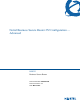
Figure 153 Console or dial backup port pin layouts
1
Table 50 Console or dial backup port pin assignments
CONSOLE Port RS – 232 (Female) DB-9F DIAL BACKUP RS – 232 (Male)
DB-9M
Pin 1 = NON
Pin 2 = DCE-TXD
Pin 3 = DCE –RXD
Pin 4 = DCE –DSR
Pin 5 = GND
Pin 6 = DCE –DTR
Pin 7 = DCE –CTS
Pin 8 = DCE –RTS
PIN 9 = NON
Pin 1 = NON
Pin 2 = DTE-RXD
Pin 3 = DTE-TXD
Pin 4 = DTE-DTR
Pin 5 = GND
Pin 6 = DTE-DSR
Pin 7 = DTE-RTS
Pin 8 = DTE-CTS
PIN 9 = NON.
The CON/AUX port also has these pin
assignments. The CON/AUX switch changes the
setting in the firmware only and does not change
the CON/AUX port’s pin assignments.
Business Secure Routers with a
CON/AUX port also have a 9-pin
adapter for the console cable with
these pin assignments on the male
end.
1
Products without flow control only use pins 2, 3, and 5.
Pi
n
1
Pi
n
6
Pi
n
9
Pi
n
5