
User's Manual
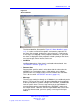
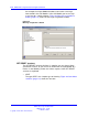
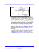
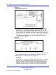
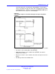
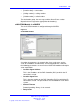
Table Of Contents
- New in this release
- Nortel DECT Messenger Administrator Guide
- Preface
- Nortel DECT Messenger overview
- eCONFIG
- Adding a DECT device to the Messenger system
- DECT Messenger Customer Engineer Manual
- Preface
- DECT Messenger overview
- DECT Messenger in a WAN or MAN network
- Licensing
- Detailed module descriptions
- What is required to run DECT Messenger
- DATABASES in DECT Messenger
- Installing and getting started
- Using eCONFIG
- Using eTM
- eDMSAPI Inbound
- eLOCATION
- Connecting National Instruments modules
- Understanding Security features
- Using eBackup
- Setting up e-mail integration (eSMTP_Server/eSMTP)
- Using eSMTP Server
- Using eSMTP
- Sending SMS messages
- V.24 - RS232 connections (eCAP, eESPA)
- Using Import/Export menu
- eLOG
- Checking diagnostics

120 DECT Messenger Customer Engineer Manual
Retry counter for retrieving information from the DAP Controller.
Default = 5.
• Retry Interval
Retry Interval time between retries. Default = 10 seconds.
• Polling Interval
Polling interval is the interval time between poling message to the DCC
to check if the connection is still alive. Default = 60 seconds.
•
>>>Board Definition
Refers to the table: eLOCATION_BOARD. This table defines the
relation between the DAP Controller and the predefined extension
number. Each DECT extension is subscribed at one DAP Controller
only.
Note:
DCC board numbers ranges from 01 to 32.
•
>>>RPN Definition
Refers to the table: eLOCATION_RPN. This table defines the relation
between the RPN number and a meaningful message. This message
must contain the location information.
•
Inbound Call Handling >>> eDMSAPI inbound event
Refers to the table: eDMSAPI_Inbound_Event. This table defines the
relation between the Calling Line ID, the Called Line ID and the Alarm
Identifier. The Alarm Identifier determines how the Alarm is processed.
•
Inbound Call Handling >>> eLOCATION inbound result
Refers to the table: eLOCATION_ INBOUND_RESULT. This table
defines the relation between the Calling Line ID, the Called Line ID and
the Group (destination) to which the alarm/message must be sent.
Connecting National Instruments modules
General
The Digital Input, Digital Output, and Analogue Input options are achieved
using FieldPoint modules of National Instruments. Figure 34 "Rail with
National Instruments FieldPoint IO Modules" (page 121) shows the
National Instruments IO modules on a rail.
Nortel Communication Server 1000
DECT Messenger Fundamentals
NN43120-120 01.06
17 October 2008
Copyright © 2003–2008 Nortel Networks
.