Nortel Communication Server 1000 SIP DECT Fundamentals Release: 5.5 Document Revision: 01.07 www.nortel.com NN43120-123 .
Nortel Communication Server 1000 Release: 5.5 Publication: NN43120-123 Document release date: 6 January 2009 Copyright © 2008-2009 Nortel Networks All Rights Reserved. Sourced in Canada LEGAL NOTICE While the information in this document is believed to be accurate and reliable, except as otherwise expressly agreed to in writing NORTEL PROVIDES THIS DOCUMENT "AS IS" WITHOUT WARRANTY OR CONDITION OF ANY KIND, EITHER EXPRESS OR IMPLIED.
. Contents New in this release Other changes 7 7 Product overview Navigation 9 Overview of SIP DECT 9 Types of SIP DECT configuration 12 Universal extension support 14 DECT handset features 16 CallPilot and Message Waiting Indication support SIP DECT capacity limitations 17 9 16 Site planning Navigation 19 Site planning overview 19 Position and use of available cabling 20 Radio coverage 20 Number of handset users 21 Site survey example 21 A normal site survey 21 Site planning example: Able-Studio
Coverage terms 51 Deployment tool 52 Prepare the tool for deployment 54 How the deployment tool works 61 Using the deployment tool 62 Handset tones interpretation 63 Rules for outdoor deployment 63 DECT Deployment Kit 2 64 DAP deployment 67 Correct audio quality problems 71 Single and multiple floor deployment 72 Single floor deployment 72 Multiple floor deployment 78 Reengineer cells for high traffic areas 83 Traffic volume 83 The cell reengineering process 83 Cell division requirements in special cases
Configuration of settings using IP DECT Configurator 136 DAP manager configuration 150 Configuration on Element manager 154 NRS configuration 163 Call server configuration 170 Routed Head Quarter configuration 173 Choice of system configuration 174 Multi site mobility network configuration 175 Subscribe a multi site DECT handset 176 Import and export subscriptions 177 Configure NRS for multi site mobility network 178 Call server configuration to MSMN 179 Configuration of Personal Call Assistant 182 Config
DAP LED indications 215 DAP firmware update 216 Remove and replace a DAP (if a new DAP is available) 217 Remove and replace a DAP (if a new DAP is not available at the moment) 218 System synchronization analysis 219 Synchronization Analyzer interface 220 Export and import SIP DECT system 228 Export a system 228 Import a system 229 DAP Controller deactivation 230 DAP Controller software deinstallation 230 DAP Controller software update 231 Troubleshooting 232 If DAP is not working 232 If you cannot make ca
. New in this release Nortel Communication Server 1000 (CS 1000) Release 5.5 introduces Nortel Session Initiation Protocol (SIP) Digital Enhanced Cordless Telecommunications (DECT). SIP DECT includes new SIP DECT Access Points (DAP). Other changes This section describes the detailed history of past releases of this document. Revision History Date Description January 2009 Standard 01.07. This document is up-issued for Release 5.5 with editorial changes. December 2008 Standard 01.06.
New in this release Nortel Communication Server 1000 SIP DECT Fundamentals NN43120-123 01.07 6 January 2009 Copyright © 2008-2009 Nortel Networks .
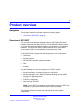
. Product overview Navigation This chapter contains information about the following topics. • “Overview of SIP DECT” (page 9) Overview of SIP DECT You can use Nortel Session Initiation Protocol (SIP) Digital Enhanced Cordless Telecommunications (DECT) to move without restriction about your work site while conducting telephone conversations, using wireless handsets. The Nortel SIP DECT system includes one or more DECT access points (DAPs or basestations) connected to the TLAN.
Product overview • • • • Call Server, Release 5.5 Signaling Server, Release 5.5 DAP software 4910b414.dwl or later DAP controller 4.1 or later (PC software) You can connect IP phones to the TLAN, connect TDM phones to the Call Server, Voice Gateway Media Cards and other required cards in Call Server. Use Voice Gateway Media Cards for IP-to-TDM calls and for conference calls involving IP phones or DECT handsets on basestations.
Overview of SIP DECT 11 Figure 1 SIP DECT configuration You can install the DHCP or TFTP services, DECT Messenger, and DAP controller on a single server or PC. However, you can also choose to install them on separate servers to enhance performance or facilitate administration. You can also install Element manager, NRS manager, and OTM on the same server, provided that the server has both a TLAN network interface and an ELAN network interface.
Product overview Use the SIP Redirect Server or SIP Proxy Server to perform the appropriate NRS configuration for SIP DECT. You can run SIP Redirect Server on Internet Server Platform (ISP) 1100, Call Processor Pentium Mobile (CP PM) signaling server, or on IBM or HP Commercial-off-the-shelf (COTS) servers under VxWorks. You can run SIP Proxy Server on IBM or HP COTS servers under Linux.
Overview of SIP DECT 13 — Disable IGMP Snooping. — Disable Spanning Tree Protocol (STP) on switch ports where SIP DECT equipment connects — If the switches serve more than one Virtual Local Area Network (VLAN), configure all SIP DECT devices in one VLAN, so they behave as one subnet • Routed Head Quarter configuration A Routed Head Quarter configuration provides seamless hand over between DAPs.
Product overview — The network must support Quality of Service (QoS) and IP connectivity throughout the Campus. — Routers must support IP multicast routing. — The IP multicast address for SIP DECT must be the same in all subnets. — multicast Time to live (TTL) must be greater than 1. — In the SIP DECT configuration, you must enter the subnet mask for all networks, for example, 255.255.248.0. Universal extension support DECT handsets subscribed on DAPs are external to Communication Server 1000.
Overview of SIP DECT 15 — For access based on the configured Coordinated Dialing Plan (CDP), compose the Target DN as follows. +. — For access based on the configured Uniform Dialing Plan (UDP), compose the Target DN as follows. ++. A UEXT corresponding to a DECT handset on the SIP DECT system reflects the idle or busy status of the associated handset by a check for a call processed between the handset and a DAP.
Product overview DECT handset features The user of a DECT handset subscribed on SIP DECT can do the following. • • Make calls to valid DNs except restricted or blocked DNs. • Put the active call on hold by pressing the R key on the handset. Return to the held call by pressing the R key. if a call is put on hold, another call can be made from the handset. After the second call is established, the user can switch between the two calls with the R key.
Overview of SIP DECT 17 Primary DN. The additional DN configured in CallPilot is the external DN of DECT handset, that is, the Target DN on the UEXT corresponding to the DECT handset. Communication Server 1000 only supports the so-called Unsolicited MWI NOTIFY model An external SIP UA cannot SUBSCRIBE to MWI NOTIFY messages and cannot request the current status of MWI for the DN from the system (by sending SUBSCRIBE messages).
Product overview • The number of available UEXTs is limited by the number of available virtual Telephone Numbers (TN) in the system • The number of DNs available for DECT handsets depends on the configured dialing plan and the availability of the Directory Number Expansion (DNXP) package (150). Nortel Communication Server 1000 SIP DECT Fundamentals NN43120-123 01.07 6 January 2009 Copyright © 2008-2009 Nortel Networks .
. Site planning Navigation This section contains information about the following topics.
Site planning ATTENTION You can use a location builder tool to plan your site. For details, see “Location builder tool” (page 239). Other modules describe in detail the procedures related to deployment. These procedures vary according to site details and user requirements. Position and use of available cabling Cables that connect the basestation to the DECT system must meet or exceed the UTP Cat 5 standard. New cabling is required if the existing cabling does not meet the standard.
Site survey example 21 Number of handset users The following information must be available. • • • The number of handset users The potential growth of handset users The areas of above average and below average traffic density Number of cells required to support traffic Traffic requirements are determined for each cell. The deployer calculates system requirements to support user traffic.
Site planning • • High handset density area Multiple systems installation Site planning example: Able-Studio This section describes a site survey for Able-Studio, a fictitious company. Follow this example to conduct the site survey. The facts for Able-Studio • The contact is Rolf Sundby at 555-0000. A guest lab coat is necessary to be on the site. Get this lab coat from Rolf. • • The sales representative has recommended DECT. • Not all users have offices and desk phones.
Site planning example: Able-Studio 23 Identify site contacts Gather the following information and enter it into the work order and the provisioning records. The installer requires the following information. Procedure 1 Identifying site contacts Step Action 1 Record company name. 2 Record the company address. 3 Record the contact name. 4 Record the contact telephone number. 5 Obtain and record scheduling times and date. 6 Obtain access to controlled areas.
Site planning Figure 4 Example of a site coverage floor plan Procedure 2 Obtaining site plans Step Action 1 Obtain two site plans or maps, with dimensions marked. Use one working copy to identify critical points, cell centers, and cell boundaries. Use one clean copy to attach to the site provisioning record for the installer, customer, or maintenance. --End-- Gather building information Gather the following information and enter it into the work order.
Site planning example: Able-Studio 25 If the building contains atriums, multiple floors, or floors not all the same shape or unusual conditions, see “Multiple floor deployment” (page 78). 5 Record the height of floors. 6 Record as much information as you can obtain about the partitioning of floors. 7 Discuss and record the details of furniture, cupboards, and machinery in the interior of buildings on every floor. 8 Ask about other building details as necessary and record this information.
Site planning 3 Record external or outdoor radio coverage. 4 Record where radio coverage is not feasible or requires specific basestations. 5 Record areas excluded from radio coverage due to the proximity of sensitive electronic equipment. 6 Record objects inside buildings that can affect radio coverage. 7 Record unsuitable basestation locations, such as stone columns, air ducts or horizontally on the ceiling. 8 Discuss what basestations are to be installed out of sight.
DAP deployment rules and requirements 6 27 Ask about and record the mobility of the users. For example, do the users move from cell to cell, or is the area of movement restricted, such that the users remain within one cell? --End-- DAP deployment rules and requirements Use the information in this section to plan the deployment of a SIP DECT system, including the locations of basestations and cells. The deployment process consists of the following.
Site planning Figure 5 DAP radio signal synchronization Due to the cellular structure of a DECT radio network, there must always be overlap in the cells with sufficient voice quality. The wider cell limit around the DAP therefore has some overlap with the other cell and reaches to the radio of the other cell. Therefore, the DAPs of the overlapping cells exchange radio signals with each other.
DAP deployment rules and requirements 29 ATTENTION If there are two or more independent Nortel SIP DECT systems with overlapping areas of coverage, it is always preferable that you configure these systems so that each system has a unique subset of carriers. When each system has a unique subset of carriers, any unnecessary interference between the systems is avoided. Note that reducing the number of available carriers reduces the maximum number of simultaneous calls in the DECT system.
Site planning Figure 6 DAP synchronization hierarchy If more than one synchronization source is present, each one forms a separate hierarchy of DAPs called a synchronization island. Automatic synchronization is performed within each synchronization island using the following rules. • After a DAP starts, it searches for existing DAPs. If it finds one with a lower RPN, it synchronizes with it. If no other DAP exists with a lower RPN, the new DAP becomes the synchronization source.
DAP deployment rules and requirements 31 the DECT manager WEB interface. Automatically assigned RPNs start at 010. If you manually assign a new RPN, ensure that it is in the range 000 . . . 00F. ATTENTION It is very important that you determine the position of the Synchronization Master before you start site planning. Place the synchronization master, which is the DAP with the lowest RPN, in the middle of your site, building, or buildings.
Site planning • IP addresses and routing must be consistent with each other to deliver the required transparency. IP addresses must be consistent with routing for normal unicast traffic as well as for the required multicast traffic. • The maximum cable length between the DAP and IP network equipment, such as a switch, is 100 meters if a Category 5, unshielded twisted pair half-duplex cable is used.
DAP deployment rules and requirements 33 Dynamic IP network addresses Network stations, which do not act as servers (PC workstations as well as DAPs), can use dynamic IP addresses assigned by DHCP. For dynamic IP addresses, there is no need to specify the MAC addresses of all the network stations in the DHCP server. The DHCP server must be configured to assign IP addresses from a certain range to unknown MAC addresses.
Site planning All network components must support forwarding of IP multicast packages. The DAP Configurator proposes a default multicast IP address (239.192.49.49). This is a multicast address in the private multicast IP address range that can be used in private IP networks. If you are not sure you can access this address, contact the local IT manager. ATTENTION You must disable IGMP Snooping and Spanning Tree Protocol on switch ports where SIP DECT equipment is connected.
DAP deployment rules and requirements 35 Figure 7 Critical points Rules and guidelines to locate cell centers Figure 8 "Cell centers" (page 36) shows the following. • • stairwell second floor plan To locate a call center, place the deployment tool at one critical point, for example P1, and then use the deployment handset to obtain a change in audio quality. The audio quality change determines the cell boundary contour. This process is repeated at an adjacent critical point, for example P2.
Site planning Figure 8 Cell centers Comply with the following as you select cell centers. • • Ensure that the installation complies with local electrical codes. • Install DAPs in a vertical position. Note that the radiation pattern differs between the horizontal and vertical positions. • • • Do not mount a DAP to a metal surface. • Position basestations at least 1 m from large concrete or stone columns and from major building structural members such as support beams or columns.
DAP deployment rules and requirements • Do not install basestations in spaces that transport air, such as ducts or plenums. • Do not mount basestations on the ceiling. 37 Coverage and signal strength calculation Synchronization between DAPs requires sufficient radio signal strength between DAPs. The following items are relevant for the signal strength for synchronization. • To achieve a good voice quality, the minimum signal strength at the receiver in the handset and DAP must be -72 dBm.
Site planning than is normal for speech. An occasionally elevated error rate does not indicate a problem with your SIP DECT system. However, if you consistently see a high error rate, then there is a problem with the deployment of your SIP DECT system. Determine cell boundaries A specific RSSI value on the handset defines the cell boundary range. Links can be made outside the cell boundary but the audio quality of the link is poor. The link drops if the handset and the basestation are too far apart.
DAP deployment rules and requirements 39 Figure 11 "Cell boundaries" (page 39) shows the following. A cell boundary for the cell center is determined by placing the deployment tool at the cell center, for example 2C1, and using the deployment handset to establish the cell boundary. The cell boundary contour is marked on the floor plan, and shown in Figure 11 "Cell boundaries" (page 39) by a dash-dot line.
Site planning Figure 12 Additional critical points and cell boundaries Mark the points, centers, and boundaries on the floor plan This section describes how to label critical points, cell centers, and cell boundaries on the floor plan. Mark the information clearly on the floor plans during the survey. The customer, the sales group, the installer, and maintenance personnel must read these floor plans. Use a different color for each cell.
DAP deployment rules and requirements 41 Table 2 Floor plan markings (cont’d.) Marking Description xCn Label each cell center using this format. Where x is the floor, and n is the next sequential cell center. Wide, colore d lines. Mark cell boundaries on the floor plan using wide, colored lines. For example, label a cell center on the second floor as 2C3. The 2 before the C indicates that the cell center is on the second floor.
Site planning Figure 14 Points, centers, and boundaries on the floor plan Figure 14 "Points, centers, and boundaries on the floor plan" (page 42) shows a typical floor plan marked-up after determining subsequent cell boundaries. The completed floor plan is as follows. • • • • • • Initial critical points are shown at P1, P2, P3, and P4. Cell centers are located where arcs from P1/P2, P3/P4 intersect. 2C1 and 2C2 show cell centers or basestation locations. Dashed and dotted lines show cell boundaries.
DAP deployment rules and requirements Figure 15 Example of initial critical points Figure 16 Cell contour of the initial critical point Nortel Communication Server 1000 SIP DECT Fundamentals NN43120-123 01.07 6 January 2009 Copyright © 2008-2009 Nortel Networks .
Site planning Figure 17 Cell contour of the closest adjacent critical point to the initial critical point Figure 18 Example of a cell center Nortel Communication Server 1000 SIP DECT Fundamentals NN43120-123 01.07 6 January 2009 Copyright © 2008-2009 Nortel Networks .
DAP deployment rules and requirements Figure 19 Example of a cell center boundary Figure 20 Example of new critical points (P8 and P9) Nortel Communication Server 1000 SIP DECT Fundamentals NN43120-123 01.07 6 January 2009 Copyright © 2008-2009 Nortel Networks .
Site planning Figure 21 Example of deployment for cell center 1C2 Figure 22 Example of deployment for cells 1C3 and 1C4 Nortel Communication Server 1000 SIP DECT Fundamentals NN43120-123 01.07 6 January 2009 Copyright © 2008-2009 Nortel Networks .
DAP deployment rules and requirements Figure 23 Identify new critical points (P11, P12, P13, P14, P15, P16, P17) Figure 24 Contours formed by critical points P11, P13, and P16 Nortel Communication Server 1000 SIP DECT Fundamentals NN43120-123 01.07 6 January 2009 Copyright © 2008-2009 Nortel Networks .
Site planning Figure 25 Cell center 1C5 formed by critical points P11, P13, and P16 Figure 26 Cell boundary 1C5 formed by critical points P11, P13, and P16 Nortel Communication Server 1000 SIP DECT Fundamentals NN43120-123 01.07 6 January 2009 Copyright © 2008-2009 Nortel Networks .
DAP deployment rules and requirements Figure 27 Example of critical point cell boundaries Figure 28 Example of cell center boundary 1C6 Nortel Communication Server 1000 SIP DECT Fundamentals NN43120-123 01.07 6 January 2009 Copyright © 2008-2009 Nortel Networks .
Site planning Figure 29 Example of a floor plan showing complete radio coverage Deployment terms Terms associated with deployment are listed in the following table. Table 4 Deployment terms Term Definition Coverage area An area where a handset can be used to make and receive calls. Cell The coverage area provided by the basestation antennas. Cell boundary The parameter of a cell coverage area.
DAP deployment rules and requirements 51 Figure 30 Example showing deployment terms Coverage terms The terms used in this guide are described in Table 5 "Coverage terms" (page 51) and illustrated in Figure 31 "Coverage terms" (page 52). Table 5 Coverage terms Term Definition Estimated number of handsets The average number of handsets expected in a particular cell. Cell The coverage area provided by a basestation. Cell boundary The edge of a cell showing the cell coverage area.
Site planning Figure 31 Coverage terms Deployment tool The DECT Deployment Tool (deployment tool) determines cell centers and cell boundaries. See Figure 40 "Deployment Kit 2 and carrying case" (page 64) and Figure 41 "Assembled Deployment Kit 2 and DeTeWe handsets" (page 66). Nortel Communication Server 1000 SIP DECT Fundamentals NN43120-123 01.07 6 January 2009 Copyright © 2008-2009 Nortel Networks .
Deployment tool Figure 32 Deployment tool carrying case and packing details Nortel Communication Server 1000 SIP DECT Fundamentals NN43120-123 01.07 6 January 2009 Copyright © 2008-2009 Nortel Networks .
Site planning Figure 33 Assembled deployment tool Prepare the tool for deployment Preparing the tool for deployment involves. • • • • “Charging the deployment tool battery” (page 55) “Charging the deployment handset battery” (page 56) “Assembling the deployment tool” (page 57) “Testing the deployment handset” (page 60) Nortel Communication Server 1000 SIP DECT Fundamentals NN43120-123 01.07 6 January 2009 Copyright © 2008-2009 Nortel Networks .
Deployment tool 55 Charging the deployment tool battery Charge the deployment tool battery for at least six hours before using. CAUTION Equipment Damage Use the Nortelbattery charger. This charger is a separately ordered item. Failure to use an automatic shutoff battery charger can damage the battery. Do not use the battery supplied with the CT2 deployment tool. The CT2 and DECT batteries are not interchangeable.
Site planning The battery must charge for at least six hours. --End-- Charging the deployment handset battery Figure 35 Deployment handset battery charger Charging time Charge the deployment handset battery for at least 12 hours before using the first time. Charge the handset at least six hours before subsequent use. Procedure 8 Charging the deployment handset battery Step Action 1 Set up the deployment handset battery charging equipment.
Deployment tool 3 57 Remove the handset from the charger after it is ready for use.
Site planning Figure 37 Deployment tool battery details Table 8 Deployment tool battery details key a battery mount b Allen screws c thumb screw d battery pack e guides f thumb screw nut g power cord h power cord receptacle i tripod Procedure 9 Assembling the deployment tool Step Action 1 Set up the tripod. Remove the tripod from its carrying case and set upright. Lock the casters. Nortel Communication Server 1000 SIP DECT Fundamentals NN43120-123 01.
Deployment tool 2 59 If required, install the extension arm fitting on the tripod. If not required, go to step 4. Place the extension arm fitting, shown in Figure 40 "Deployment Kit 2 and carrying case" (page 64), onto the brass fitting on the top of the tripod. 3 If required, secure the extension arm fitting. Use the Allen key attached to the extender arm to secure the extension arm fitting Allen screw. 4 Mount the extension arm on the tripod.
Site planning Plug the basestation power cord connector into the upper right edge of the battery. --End-- Testing the deployment handset Figure 38 Handset display and keypad details Procedure 10 Testing the deployment tool handset Step Action 1 Start the test and establish a link with the basestation. Remove the handset from its charger. 2 Turn on the handset. Press the shift key and press the ON/OFF button. DECT HANDSET appears on the handset display.
Deployment tool 3 61 Select system mode. Press the shift key and press the local key. The handset displays SYSTEM. 4 Select the monitor mode. Press the star (*) key. The handset displays MONITOR MODE. 5 Select the monitor mode code. Press the lock button. The handset displays CODE. 6 Enter the monitor mode code. On the dial pad, enter 2530. Press the lock button. 7 Interpret the handset RSSI display and test tone.
Site planning The display, shown in Figure 39 "Deployment handset link display" (page 61), means as follows. • • • • A circle and dot indicates a locked signal. The antenna symbol indicates a link establishment. The number 10 indicates an RSSI value. The dash, equal sign and shaded box icons indicate signal strength. The maximum RSSI is 10. As signal strength diminishes, the number 10 decreases and the icons disappear.
Using the deployment tool 63 Do not select a cell edge that has an RSSI reading of less than 6. However, keep the following in mind. • There can be environments that cause poor tone at a RSSI meter reading of between 7 and 10. In this case, contact Nortelsupport team for assistance. • The tone stops after the radio link is lost. Handset tones interpretation The handset tones indicate how close the handset is to the deployment tool basestation.
Site planning 11 Charge the batteries indoors. --End-- DECT Deployment Kit 2 The DECT Deployment Kit 2 is shown in Figure 40 "Deployment Kit 2 and carrying case" (page 64). For more information, see the DeTeWe User Manual that accompanies each kit. Figure 40 Deployment Kit 2 and carrying case The following information can be used in conjunction with the DeTeWe User Manual that accompanies the deployment tool.
DECT Deployment Kit 2 65 — Press Menu — Scroll to System — Dial ***76# — Scroll to Site Survey — Press OK • The FE value for the PP is the number of detected Sync/ACRC errors within the last 100 receiving frames, for example, 1 sec. For proper deployment, the FE value must not exceed 4. • The FE value is for the FP is the number of received Q1/Q2 bit information within the last 100 receiving frames, for example 1 sec. For proper deployment, the FE value must not exceed 4. • An RSSI value of -80dBm ..
Site planning Figure 41 Assembled Deployment Kit 2 and DeTeWe handsets Nortel Communication Server 1000 SIP DECT Fundamentals NN43120-123 01.07 6 January 2009 Copyright © 2008-2009 Nortel Networks .
DAP deployment 67 Figure 42 Deployment Kit 2 basestation DAP deployment To deploy a DECT system follow Procedure 12 “Deploying a DECT system” (page 67). Procedure 12 Deploying a DECT system Step Action 1 Identify and mark initial critical points. Mark critical initial points on the floor plan with the following symbol. Figure 15 "Example of initial critical points" (page 43) shows the initial critical points: P1, P2, P3, P5, P6 and P7.
Site planning a Set up the deployment tool basestation. Raise the deployment tool basestation as high as possible, or until it is at the height recommended for basestations. b Establish a link. See “Deployment tool” (page 52) for details. c Measure the range into the coverage area in a few directions to determine where a cell center can be located and still be within range of the critical point. Listen to the deployment tool handset while moving away from the basestation.
DAP deployment 69 c See the floor plan and check audio quality in user offices within the cell. If a user office is in a zone where audio quality deteriorates, relocate the cell center closer to the critical point or the office. d Walk into all of the areas (rooms) necessary to demarcate the complete cell boundary. Radio signals travel further in uncluttered areas than in cluttered areas. Record the cell boundary.
Site planning See step 6 for details. 9 Using the critical points from step 7, demarcate new cell contours, a new cell center and a new cell boundary. See step 2 to step 5 starting on step 2 for details. Note: Cell contour arcs must pass near the cell boundary of adjacent cells. For an example of this, see Figure 21 "Example of deployment for cell center 1C2" (page 46). 10 Demarcate additional cell contours, centers and boundaries at the other end of the building.
Correct audio quality problems 71 and P16" (page 48). Critical points P11, P13 and P16 form the following.
Site planning This includes washrooms, coffee areas, and meeting rooms. Do not speculate where users can make calls. --End-- Single and multiple floor deployment Whether the deployment situation involves a single floor or multiple floors, the deployment process uses basic rules. • • Deploy the external or outdoor areas first. • Finish by deploying the middle of the coverage area. Deploy from one side of the coverage area and then deploy the opposite side of the coverage area.
Single and multiple floor deployment 73 By deploying the site using this method, cell centers are distributed throughout the site. If the site is deployed from one end to the other, cell centers can be clustered at one end of the site. Single-cell deployment Always start with the single-cell technique regardless of the width between the two critical points. Using this technique, you can find one cell center that serves two critical points, as shown in Figure 43 "Single cell distance" (page 73).
Site planning After the display value changes from 7 to 6, the cell boundary is detected. 5 Record the cell boundary by marking a small X on the floor plan where the cell boundary value was reached. Use a pencil that is the same color as the critical point where the deployment tool is located. 6 Repeat step 4 and 5 several times, walking in different directions to determine where the cell center can be located and still remain within range of the critical point.
Single and multiple floor deployment 75 Double cell deployment Use the double cell technique only if referred here from the single cell technique. Before beginning this technique, there must be two critical points that one cell center cannot serve. Using the double cell technique, find two locations for cell centers that cover three critical points, as shown in Figure 44 "Double cell distance" (page 75).
Site planning center and the cell boundary, see “Multi cell deployment” (page 76). 10 Choose a position on the floor plan for the cell center that meets the following requirements. a is furthest from the critical points and still provides good audio quality at the critical point, b complies with the “Rules and guidelines to locate cell centers” (page 35), and c is in the coverage area. 11 Mark each cell c on the floor plan and label them 1C1 and 1C2.
Single and multiple floor deployment 77 Figure 45 Multi-cell distance Procedure 16 Multi-cell deployment Step Action 1 Choose a position on the floor plan for the cell center that meets the following requirements. a is furthest from the critical points and still provides good audio quality at the critical point, b complies with the “Rules and guidelines to locate cell centers” (page 35), and c is in the coverage area. 2 Place the deployment tool at critical point P1. 3 Establish a link.
Site planning 10 Mark each cell center on the floor plan and label them 1C1 and 1C2. 11 Place the deployment tool at each cell center. 12 Locate the cell boundary and mark it on the floor plan. (Mark the contours in different colors for easy differentiation of cell centers.) 13 Define and mark on the plan subsequent critical points, where each cell boundary crosses the edge of the coverage area.
Single and multiple floor deployment 79 Checking for through-the-floor coverage The first step in covering a multi-floor building is assessing the availability of through-the-floor coverage. In buildings mainly constructed of wood, through-the-floor coverage can be used. However, due to the construction of most modern buildings with raised floors, high metal content, and reinforced concrete, through-the-floor coverage with DECT is limited.
Site planning For example, if floor 2 of an office tower is laid out with cubicle style offices with a perimeter of enclosed offices, and floor 3 is designed and laid out in the exact same manner, both floors can have the exact same installation profile for basestations. All floors do not have the same layout If there are deviations in the floor plan from floor to floor, use the critical point method to deploy each distinct floor. For more information, see “Prepare the tool for deployment” (page 54).
Single and multiple floor deployment 81 • • • Plan atriums to their full height. • Do not put cell centers in an atrium if you intend for them to serve adjacent areas. • • To serve adjacent areas, put the cell centers into these areas. • If cell centers in adjacent dense areas serve one floor of an atrium, verify the coverage of the cell on all of the floors that meet with the atrium. Plan an atrium as one full size room, not floor by floor.
Site planning Overlap can be difficult to achieve where coverage is received from the floor above or the floor below. Internal structures can cause overlap deficiencies. Cell centers do not need to be located on the same floor or an adjacent floor of the area that it is covering. Place cell centers within the cell boundary, as indicated by the deployment tool.
Reengineer cells for high traffic areas 83 Figure 48 Locating redundant cells Reengineer cells for high traffic areas To accommodate the demand in high traffic areas, follow the “The cell reengineering process” (page 83). Traffic volume The deployment process ensures coverage throughout the service area. It does not, however, take into account the effect of traffic. To support the volume of telephone calls in cells that carry high traffic, it is necessary to increase the number of cells deployed.
Site planning • “Calculating the number of users with an office outside the cell who walk into the cell” (page 87). • • • • • “Calculating the number of users without an office” (page 88). “Totalling the estimate for users in a cell” (page 89). “Calculating the data for all remaining cells” (page 89). “Creating a table to document telephone types in a cell” (page 90). “Determining cell reengineering” (page 91).
Reengineer cells for high traffic areas 85 Separating the coverage area and recording the number of offices Figure 49 Example of dividing the coverage area and recording offices Procedure 18 Separating the coverage area and record the number of offices Step Action 1 Divide the floor plan into cell areas.
Site planning Table 9 Estimate users in a cell Estimate for: 1C1 1C2 1C3 1Cn Users inside the cell with an office Users with an office outside of a cell who walk into the cell Users without an office Users in a cell Procedure 19 Creating an estimate table Step Action 1 Make an estimate table. Include as many columns as there are cell centers. 2 Label the rows. Example shown in Table 9 "Estimate users in a cell" (page 86). 3 Label each column heading with the cell center indicator.
Reengineer cells for high traffic areas 87 Use the formula: (users with an office in the cell × 0.7) 2 Enter the result in the row, users inside the cell with an office. In the example shown in Figure 49 "Example of dividing the coverage area and recording offices" (page 85), twelve users in cell 1C1 spend 70% of their time in their offices (12 × 0.7 = 8.4) . --End-- Note: Traffic engineering has determined that handset users with an office spend seventy percent of their time within their home cell.
Site planning minus cell 1C1. Accordingly, an estimate of 3.2 walk-in users can be in cell 1C1. --End-- Calculating the number of users without an office Table 12 Example of the table third row calculation Estimate for: 1C1 Users inside the cell with an office 8.4 Users with an office outside of a cell who walk into the cell 3.
Reengineer cells for high traffic areas 89 Totalling the estimate for users in a cell Table 13 Example of the table first column total Estimate for: 1C1 Users inside the cell with an office 8.4 Users with an office outside of a cell who walk into the cell 3.2 1C2 1C3 1C4 1C5 1C6 1C7 0 Users without an office 11.
Site planning Procedure 24 Calculating the data for all remaining cells Step Action 1 Repeat the last four tasks to calculate all the remaining user cell estimates. 2 Enter the result in the estimate table. The information in Figure 49 "Example of dividing the coverage area and recording offices" (page 85), is shown entered into Table 14 "Example of a completed estimate table" (page 89). This table is used to note the results of the calculations for cells that require reengineering.
Reengineer cells for high traffic areas 91 The information in this table is used to determine the number of cells that require reengineering. --End-- Determining cell reengineering Table 16 Example of a completed estimate table Estimate for: 1C1 1C2 1C3 1C4 1C5 1C6 1C7 Users inside the cell with an office 8.4 0.7 21.0 14.7 0.7 4.9 2.1 Users with an office outside of a cell who walk into the cell 3.2 3.7 2.3 2.7 3.7 3.4 3.6 0 0 0 0 0 0 0 11.6 4.4 23.3 17.7 4.4 8.3 5.
Site planning Procedure 26 Determining cell reengineering Step Action 1 Locate the estimate for users in the first cell. In the example shown in Table 16 "Example of a completed estimate table" (page 91), the handset estimate is 11.6. 2 Determine the telephone types in the first cell. In the example shown in Table 16 "Example of a completed estimate table" (page 91), the telephone type is H&W. 3 Locate the telephone type column in Table 16 "Example of a completed estimate table" (page 91).
Cell division requirements in special cases 93 The formula assumes that users are located evenly throughout the cells. However, most users offices are clustered in specific areas of a building. The formula has limitations, as cells can vary in size. The method described starting on “The cell reengineering process” (page 83) gives more accurate cell division results. A mix of users with and without wired telephones in a cell Use this procedure for mixed handset users.
Site planning Table 19 Adjustment for users without wired telephones (cont’d.
High handset density deployment 95 5 Use Table 19 "Adjustment for users without wired telephones" (page 93) to determine the criteria shown in the left column to determine if the cell has to be re-sized in the same manner described in the section Determine cell reengineering. --End-- High handset density deployment The high handset density deployment includes limiting the expected number of handsets for each cell center.
Site planning • If the handset users in cell 1C1 are all handset only users, one cell can support 39 handset only users. Therefore, four cells are needed to support 140 users (140÷39 = 3.5 cells). • If the handset users in cell 1C1 are handset and wired telephone users, and one cell can support 83 users, two cells are needed to support 140 handset and wired telephone users (140÷83 = 1.
Deployment review 8 97 Repeat the anticipated handsets for each cell calculation to ensure that each smaller cell provides appropriate traffic coverage to the users in the area. --End-- Deployment review Review the plan to ensure that the sales group can use it. The plan must be complete for the installer, legible for maintenance purposes, and acceptable to the customer.
Site planning Figure 51 Example of a completed floor plan Nortel Communication Server 1000 SIP DECT Fundamentals NN43120-123 01.07 6 January 2009 Copyright © 2008-2009 Nortel Networks .
. Hardware installation Navigation This chapter contains information about the following topics. • • • • “Call server” (page 99) “Signaling server” (page 99) “PC (DAP controller)” (page 100) “DECT Access Points” (page 100) Call server Install and connect the appropriate call server to your local Ethernet network. Communication server types are supported.
Hardware installation Signaling Server types are supported. • • • • ISP1100 CP PM signaling server COTS IBM X306m COTS HP DL320-G4 For details about Signaling Server hardware installation, see Signaling Server Installation and Commissioning (NN43001-312) . PC (DAP controller) Minimum specifications for the PC are as follows. • • • • 2.
DECT Access Points 101 Ensure that the DAPs are installed according to the location recommendations. For more information, see “DAP deployment rules and requirements” (page 27). Nortel Communication Server 1000 SIP DECT Fundamentals NN43120-123 01.07 6 January 2009 Copyright © 2008-2009 Nortel Networks .
Hardware installation Nortel Communication Server 1000 SIP DECT Fundamentals NN43120-123 01.07 6 January 2009 Copyright © 2008-2009 Nortel Networks .
. Software requirements Navigation This chapter contains information about the following topics. • • • “Call server software” (page 103) “Signaling server software” (page 103) “DAP controller software” (page 103) Call server software For details about Communication Server 1000S CP PM software installation, see Communication Server 1000E Upgrade - CS 1000S to CS 1000E (NN43041-470) .
Software requirements — Windows 2000 Professional or Windows 2000 Server (SP4 required) — Windows 2003 Server (SP1 or SP2 required) — Windows 2003 R2 — Windows XP Professional (SP2 required) This document does not provide the steps you must follow to install the operating system. For information about installing Windows, see the documentation that accompanied the Windows software.
DAP controller software • • • 105 From 3000 to 22229 – multicast From 28000 to 28017 – DAP Controller services 30160 – CDA services Note: If you change default ports in the IP DECT Configurator, ensure that the firewall settings are updated correctly. Internet information services The DAP controller or manager runs as a service under Windows. Because the management interface is available through a Web interface, the Web Server IIS must be installed.
Software requirements 6 Insert the Windows CD-ROM and follow the on-screen instructions. --End-- Check IIS on PC with Windows 2000 Use the steps in the next procedure to determine whether IIS is started, and to start it if necessary. Procedure 31 Checking IIS on PC with Windows 2000 Step Action 1 Open Internet Explorer on the PC where IIS is installed. 2 In the address bar in Explorer, enter localhost/iisHelp/ and then press enter. IIS is running if Help Information appears.
DAP controller software • 107 You must have the appropriate Windows installation CD-ROM available to complete this procedure. Procedure 32 Installing IIS on a PC with Windows 2003 Step Action 1 Click Start > Control Panel. 2 Select Add/Remove Programs. The Add/Remove Programs window appears. 3 Click Add/Remove Windows Components. 4 In the Components window, double-click Application Server 5 In the Components window, check ASP.NET. 6 Select Internet Information Services and click Details.
Software requirements 8 Click OK. 9 Click OK again. 10 Follow the instructions provided by the install Wizard, and insert the Windows CD-ROM as prompted. 11 Close the Add/Remove Programs window and close the Control panel window. --End-- Restart IIS on a PC with Windows 2003 Use the steps in the next procedure to restart IIS. Procedure 33 Restarting IIS Step Action 1 Click Start and open the Control Panel. 2 Click Administrative Tools. 3 Click Computer Management.
DAP controller software 6 109 Select Restart. IIS is now restarted. --End-- Check IIS on a PC with Windows 2003 Use the steps in the next procedure to determine whether IIS is started. Procedure 34 Checking IIS on a PC with Windows 2003 Step Action 1 Open Internet Explorer on the PC where IIS is installed. 2 In the address bar in Internet Explorer, enter localhost/iisstart .htm. If IIS is not running properly you can restart IIS. See Procedure 33 “Restarting IIS” (page 108).
Software requirements Install IIS on PC with Windows XP Use the steps in the next procedure to install the IIS function on a PC with Windows XP. • You must have the appropriate Windows installation CD-ROM available to complete this procedure. Procedure 35 Installing WEB Server IIS with Windows XP Step Action 1 Click Start > Settings > Control Panel . 2 double-click Add/Remove Programs. The Add/Remove Programs window appears. 3 Click Add/Remove Windows Components.
DAP controller software 111 Check IIS on PC with Windows XP Use the steps in the next procedure to determine whether IIS is started. Procedure 36 Checking IIS on a PC with Windows XP Step Action 1 Open Internet Explorer on the computer where you want to install the DAP manager. 2 Enter the URL localhost/localstart.asp. 3 Ensure that the Internet Information Services (IIS) page appears.
Software requirements DHCP servers and TFTP servers are the network components of the Microsoft Windows 2003 Server and the Microsoft Windows 2000 Server. Install these servers as services for SIP DECT system functioning. See “DHCP and TFTP servers” (page 111) for details about Microsoft Windows 2000, 2003 DHCP and TFTP server installation and configuration. The DAP controller software Release 4 includes DHCP and TFTP servers that can be configured from the IP DECT Configurator.
DAP controller software 113 The DHCP server can be installed on the same server or on another PC that runs the TFTP server. Note: The Microsoft DHCP server installation files are located on the Microsoft Windows 2000/2003 Server CD-ROM package. Licensing or registration charges or both may apply. --End-- The DHCP server can be installed on the same server or on another PC that runs the TFTP server. The Microsoft DHCP server (Windows 2000/2003) is in the Microsoft Windows 2000/2003 Server CD-ROM package.
Software requirements 6 Click OK. 7 Click Next. 8 Insert the Windows 2003 CD-ROM as prompted. 9 Finish the procedure using the instructions on the screen. 10 Close the Add/Remove Programs window and close the Control panel window. --End-- Procedure 39 Configuring the Settings for SIP DECT Step Action 1 Start the DHCP manager: Start > Programs > Administrative Tools > DHCP. The DHCP Administration Tools window appears.
DAP controller software 2 Select the active DHCP server and create a new scope: Menu-bar > Action > New Scope. The New Scope Wizard starts. 3 Click Next in the first screen of this wizard. 4 Enter a name and description for the new scope, for example, SIP DECT. 5 Click Next in the naming screen of this wizard to get the IP address range. 115 The window New Scope Wizard—IP address range appears. Nortel Communication Server 1000 SIP DECT Fundamentals NN43120-123 01.
Software requirements 6 Define a range of IP addresses for the DAPs used, for example, 192.168.100.200- 210. 7 Define the associated subnet mask, for example 255.255.255.0. 8 Click Next. The window New Scope Wizard—Exclusion of an IP address range appears. Nortel Communication Server 1000 SIP DECT Fundamentals NN43120-123 01.07 6 January 2009 Copyright © 2008-2009 Nortel Networks .
DAP controller software 9 117 Enter the Start IP address and End IP address values to exclude, for example the IP addresses of DHCP server and the TFTP server. This is only necessary if the IP address or addresses of equipment with a fixed IP address is within the DHCP address range. If they are not within the DHCP address range, leave this field blank. 10 If you entered IP address ranges in the step above, click Add to save the exclusion list. 11 Click Next. The Lease Duration window appears.
Software requirements 12 Set the desired lease duration of the granted IP addresses to the desired value. 13 Click Next. The New Scope Wizard—Configure DHCP options appears. Nortel Communication Server 1000 SIP DECT Fundamentals NN43120-123 01.07 6 January 2009 Copyright © 2008-2009 Nortel Networks .
DAP controller software 14 Select No and click Finish. The newly created scope appears. Under the newly created scope there is a sub line called Scope Options. 15 Right-click Scope Options and select Configure Options. The Scope Options page appears. Nortel Communication Server 1000 SIP DECT Fundamentals NN43120-123 01.07 6 January 2009 Copyright © 2008-2009 Nortel Networks .
Software requirements 16 Select the check box Option 066 and enter the IP address of the TFTP server, for example 192.168.100.10. This can be the IP address of your DAP controller or manager, if the TFTP server is running there. Do not click OK yet, but continue with the next step. 17 Check Option 067 for the boot file name. Enter dapcfg.txt. 18 Select the check box Option 3 and enter the Router or Default Gateway IP address, for example 192.168.100.1. Click Add.
DAP controller software 19 Click Apply to save the changes and OK to leave the screen. 20 Right-click Scope and select Activate. 121 Now your DHCP server is configured correctly. 21 Close the DHCP window --End-- TFTP server There are many types of TFTP servers available, including shareware and freeware. A TFTP server must handle several accesses at the same time, because several accesses take place at the same time when the Nortel Communication Server 1000 SIP DECT Fundamentals NN43120-123 01.
Software requirements DAPs start up simultaneously. Only a few TFTP servers can handle more than one access at the same time. Some of these crash if the number of accesses is too high. Follow the steps in the next procedure to install a TFTP server on the Windows 2000 Server and the Windows 2003. Procedure 40 Installing the TFTP server Step Action 1 If you have Windows 2003, go to Start > Control Panel in Windows. If you have Windows 2000, go to Control Panel through Settings.
DAP controller software 123 8 Close the Add/Remove Programs window and close the Control panel window. 9 Click yes after you are prompted to restart the computer. --End-- Procedure 41 Starting the TFTP server Step Action 1 If you have Windows 2003, go to Start > Control Panel. If you have Windows 2000, go to Settings > Control Panel. 2 Open Administrative Tools. 3 Open Services. The Services window appears. 4 Select Trivial FTP Deamon.
Software requirements --End-- Built-in DHCP and TFTP servers The DAP controller software Release 4 comes with a built-in DHCP and TFTP server. The built-in DHCP and TFTP servers do not require manual configuration, because the IP DECT Configurator sets up the configuration. ATTENTION You can configure a Built-in DHCP and TFTP server only after you install the IP DECT Configurator. See “DAP Controller” (page 130) for details.
DAP controller software 125 Procedure 42 Configuring the built-in DHCP server using the IP DECT Configurator Network Settings Window Step Action 1 Start the IP DECT Configurator and select Modify the system. 2 Choose the system to modify. Note: If you are configuring a new system, follow the steps in these procedures before setting up built-in DHCP server.
Software requirements 12 Click Apply. 13 Start the DHCP server with Start > All Programs > DAP controller. 14 Reboot the DAPs. Note: If you are configuring a new system, follow the steps in Procedure 51 “Configuring SIP Settings” (page 141) instead of rebooting DAP --End-- Built-in TFTP server The DAP controller 4 comes with a built-in TFTP server that runs as a service under Microsoft Windows.
DAP controller software 127 The DAPs can be installed in an IP environment without a DHCP server, a TFTP server, or both. Such an IP environment can be a VLAN within the company network where the IT manager does not allow a DHCP server. This IP environment can also be a branch office where a few DAPs are installed, without a DHCP server.
Software requirements 3 Select Unlimited for Lease duration for DHCP clients. 4 Click on the Advanced Tab and select Both for Assign IP addresses dynamically to clients of and Unlimited for Lease duration for OOTP clients. Nortel Communication Server 1000 SIP DECT Fundamentals NN43120-123 01.07 6 January 2009 Copyright © 2008-2009 Nortel Networks .
DAP controller software 5 129 Click OK to save changes. --End-- DAP configuration without DHCP or TFTP servers You can set up DAP configuration without DHCP or TFTP servers using the Network Settings window of the IP DECT Configurator. Use the following procedure to configure a DAP to store IP address and the configuration data. Procedure 44 Storing IP address and configuration data on a DAP Step Action 1 Start the IP DECT Configurator and select Modify the system. 2 Choose the system to modify.
Software requirements 8 Ensure that the DHCP server is running and that the TFTP server is running. 9 Reboot the DAPs. The IP data and configuration data is now stored into the DAPs and the DAPs can function without the DHCP and TFTP servers. --End-- DAP Controller Use the information in this section to install the DAP Controller from the CD. You only need to execute this procedure once because the installation can be used for as many system configurations as you want.
DAP controller software 131 .NET 1.1 Framework. Would you like to install it now? 2 Click Yes to install Microsoft .NET Framework 1.1 software. The Microsoft .NET Framework 1.1 Setup: End User License Agreement page appears. 3 Click I agree and then click Install. After the Microsoft .NET Framework 1.1 is successfully installed, Microsoft .NET Framework 1.1 Setup: Setup Complete page appears. Note: Wait while the installation completes; this can take several minutes.
Software requirements 9 Select Standard and click Next. If you want to customize the installation, select Custom. 10 Click Next. The Select Installation Address page appears. Do not change the default values in the fields CDS and Port Number. The system has collected enough information to install the software. 11 Click Next. The Ready to install the program page appears. 12 Click Install to start the installation. The system installs the software.
DAP controller software 133 The InstallShield Wizard Completed page appears when the installation is complete. 13 Click Finish. The DAP Configurator starts automatically so that you can configure your SIP DECT system. --End-- Nortel Communication Server 1000 SIP DECT Fundamentals NN43120-123 01.07 6 January 2009 Copyright © 2008-2009 Nortel Networks .
Software requirements Nortel Communication Server 1000 SIP DECT Fundamentals NN43120-123 01.07 6 January 2009 Copyright © 2008-2009 Nortel Networks .
. System configuration Navigation This chapter contains information about the following topics.
System configuration • • • • • • • D-Channel: 5 Route: 6 Access Code: 9 Location code: 442 SIP Route ACOD: 6 SIP domain name: mera.ru Signaling Server hostname: SS_Node55_ldr Configuration of settings using IP DECT Configurator The IP DECT Configurator is a tool for creating configuration files for the DAP controller and DAPs. The IP DECT Configurator is installed and launches automatically with the installation of the DAP controller software.
Simple SIP DECT configuration 137 Procedure 46 Launching the IP DECT Configurator Step Action 1 Select Start > Programs > DAP controller > DAP Applications > DAP Configurator. The IP DECT Configurator window appears. If your network card does not have a fixed IP address, the following error message appears after the application launches. To correct this error, assign a fixed IP Address to the network card in your DAP controller PC and launch the application again.
System configuration The IP DECT Configurator main window shown in Figure 1 "SIP DECT configuration" (page 11) has three sections. 1. The top section shows the Settings buttons. 2. The left section shows the System Control buttons. 3. The middle section shows the data information. --End-- Procedure 47 Adding a new system using the IP DECT Configurator Step Action 1 In the IP DECT Configurator main window, click the New System button in the System Control settings on the left of the window.
Simple SIP DECT configuration 2 139 Enter the System name, for example, System_1. Note: Do not enter any special characters in the name of your SIP DECT system that cannot be used in the name of the folder you create for the SIP DECT system. The folder and the SIP DECT system share the same name. 3 In the General Settings window, enter the path to the firmware, the DAP package file, for example, C:\tftpdroot\4910b420.dwl. 4 Click Apply.
System configuration 3 Enter the DAP controller Configuration: DC IP address, which is the PC IP address where your DAP controller is installed. An example of this address is 192.168.100.10. ATTENTION The DAP Controller PC must have a static IP address and be in the same subnet as the DAPs. If the DAP Controller PC is in a different subnet, you must configure the Routed Head Quarter. See “Routed Head Quarter configuration” (page 173).
Simple SIP DECT configuration 141 2 Select the network card connected to the SIP DECT system. 3 Select the check box next to Run TFTP server on this PC and select the following. 4 • Windows TFTP server on this PC if you use an MS Windows TFTP server. OR • 3com TFTP server on this PC if you use a built-in TFTP server. Configure the DHCP server. • If you use an MS Windows DHCP server, click Apply. OR • If you use a built-in DHCP server, see “Built-in DHCP server” (page 124).
System configuration 2 Select Nortel for Predefined SIP Server configurations. 3 In the Advanced SIP Settings window, enter the domain name. 4 Select the check box for sdp_late_sendrecv and select no. 5 Select the check box for sdp_playload_size and select 20 or 30 as required. You must configure the same payload value for the G711 codec in Signaling Server. 6 Select the check box for sdp_DTMF_rfc2833 and select nortel_info_type.
Simple SIP DECT configuration 12 143 Optionally, select the check box for t_overlap_first and enter the value (in seconds) to define how long the DAP waits for the user to dial the first digit. If no new digit is dialed within the specified period of time, the DECT handset goes on-hook automatically.
System configuration 2 Enter an 8 digit hexadecimal string for the Primary Access Right Identity or PARI, for example, 10052007. Note: The worldwide unique PARI for your DECT system must be issued by the European Telecommunications Standards Institute (ETSI). For more information, see www.etsi.org. ATTENTION Ensure you enter the correct PARI. You need to reinstall the DAP Controller software and re-subscribe all DECT handsets if you change the PARI.
Simple SIP DECT configuration 145 carriers for each system. When you allocate a unique subset of carriers for each system, you avoid unnecessary collisions between them. For example, if there are two independent DECT systems, you can turn off carriers 0-4 in one system and turn off carriers 5-9 in the other system. Turning off carriers reduces the maximum number of simultaneous calls. For this reason, you can be required to install extra DAPs to achieve the desired call capacity of the DECT system.
System configuration In this window, you can configure the following: • Performance Settings — Performance Counters Configuration – Interval UPM generation every _____ minutes – Interval EPM generation every _____ minutes – Start measurement at – Stop measurement at — Create performance counters every _____ — Keep performance data for ______ days.
Simple SIP DECT configuration 147 — Threshold/Time — Alarm reaction time 2 In Performance Settings, under Performance Counters Configuration fill the field in Interval UPM generation every _____ minutes or accept the default of 1440 minutes, which equals one day. This interval specifies how often User Performance Measurement files are generated. 3 Fill n the field in Interval EPM generation every _____ minutes or accept the default of 15 minutes.
System configuration 12 Fill in the field next to Email from: with the email address of the originator. Note: Normally, the SMTP server does not verify the email address of the originator. This means you can enter any email address in this field. 13 Fill in the two boxes after Channel Occupation. In the Threshold box, specify the percentage. In the Time box, specify a time in seconds. Channel Occupation defines the conditions for generating an email on DAP channel occupation.
Simple SIP DECT configuration 149 Procedure 55 Saving the system Step Action 1 To save the new system you created with the IP DECT Configurator, click Apply and then select Save system from the menu on the left. 2 In the System Control section in the left of the IP DECT Configur ator main window, click the Activate/Deactivate/System Status button The Activate/Deactivate/System Status window appears. 3 Click the Activate all button.
System configuration Procedure 56 Enabling or re-enabling the DAPs Step Action 1 To enable or re-enable the DAPs, power on the DAPs. --End-- DAP manager configuration The following procedures are described in this section. • • • “Rebooting DECT Access Points” (page 150) “Adding number range” (page 151) “Subscribing a DECT handset” (page 152) Rebooting DECT Access Points DECT Access Points need to be rebooted following software upgrades.
Simple SIP DECT configuration 151 DECT Access Points are identified by their Radio Part Number (RPN). In the work space, the DECT manager shows the status of the present DAPs. The RPN of a DAP is modified by editing the RPN field. In the DAP manager task area, choose one of the following options. • • • Reboot—Select this option to reboot a selected DAP. Reboot All—Select this option to reboot all DAPs in the list. Delete—Select this option to remove a DAP from the list.
System configuration Procedure 58 Adding Number Range Step Action 1 Select Add Number Range from the menu list on the left. 2 Define DNs for the DECT handsets. ATTENTION The length of all DNs subscribed on DAPs must be the same. --End-- Subscribing a DECT handset Before you can use a handset (also known as portable telephone, portable part or PP), subscribe each handset to the system, and ensure that each handset is registered by the DECT manager.
Simple SIP DECT configuration 2 153 Select the required available extension number or numbers. If the required number is not visible, select another page. The page number is displayed in the top and bottom rows of the subscriptions table. 3 Click Enable. The status of the configuring subscription record changes from "Free" to "Enabled" and the PIN is shown.
System configuration Sometimes it is necessary to enter PARK code first. The PARK code is displayed on the left at the bottom of the Subscriptions page. Note: If the PIN is not entered within 16 minutes, the subscription mode is terminated for that specific extension number and the subscription process must be started from the beginning. 6 Enter the name and DN of the SIP-DECT system. The DN is displayed on the handset screen.
Simple SIP DECT configuration 155 Creating a new customer Use Element manager and follow the steps in the next procedure to create a new customer or modify information about an existing customer. Procedure 60 Creating a new customer or modifying information about an existing customer Step Action 1 Select Customers from the menu list on the left. 2 Click the Add button on Customers list page. The New Customer X Property Configuration page appears. 3 Fill in customer number, for example 0.
System configuration 6 Click Submit. --End-- Adding a D-Channel To add a D-Channel using Element manager, complete the following procedure. Procedure 62 Adding a D-Channel Step Action 1 Select Routes & Trunk > D-Channels from the menu list. 2 On D-channels list page select a number, for example 5, for D-Channel Number and DCH for type, and then click Add. The D-Channels Y Property Configuration page appears. 3 Select DCIP for CTYP, ISLD for USR and SL1 for IFC.
Simple SIP DECT configuration 157 6 Select the check box for VTRK and enter the VTRK zone number, for example 1, for ZONE. 7 Select the Node ID of the signaling server for NODE. 8 Select SIP for PCID. 9 Select the check box for ISDN. 10 Select ISLD for MODE. 11 Select the DCH created previously, for example 5. 12 Select SL1 for IFC and 1, for example, for the Private Network Identifier (PNI). 13 Select the check box for NCNA and INAC. 14 Select CDP for CTYP.
System configuration 10 Enter the route number you configured previously and the route member, for example 6 1, for RTMB. 11 Select WNK both STRI/STRO and 1 for CHID. 12 Enter a terminal number (tn) for TN, for example 96 0 0 0. Refer to the superloop configured previously in this procedure. Note: TN format: L s cu, where L = virtual superloop, s = shelf, c = card, and u = unit. 13 Click Edit to configure Class of Service (CLS). 14 Select Digitone Dial Pulse (DTDP) for Dial Pulse.
Simple SIP DECT configuration 159 Procedure 66 Creating ESN Control Block Step Action 1 On the ESN page, select Customer X > Network Control & Service > ESN Access Code & Parameters (ESN). The ESN Access Codes and the Basic Parameters page appears. 2 Enter 10 for MXDM/MXRL/MXIX/MXFC/MXFS/MXLC/MXSC, 9 for AC1, 6 for ERDT, 0 for MXSD. 3 Click Submit. --End-- Adding digit manipulation block To add digit manipulation block using Element manager, follow the steps in the next procedure.
System configuration 3 Select the route created before, for example 6, for ROUT and 1 for DMI. 4 Click Submit. --End-- Adding location code (UDP) To add a location code (UDP) using Element manager, follow the steps in the next procedure. Procedure 69 Adding location code (for UDP) Step Action 1 On the ESN page, select Customer X > Numbering Plan (NET) > Access Code 1 > Location Code (LOC). 2 Enter a 3-digit code, for example 442, and click Submit.
Simple SIP DECT configuration 161 If you plan to create a Branch Office Configuration, seePerform configuration on Element Manager. --End-- Configuring the signaling server To configure the Signaling Server using Element manager, follow the steps in the next procedure. Procedure 71 Configuring the signaling server Step Action 1 Select System > IP Network > Node: Server, Media Cards. The Node Configuration page appears. 2 Select Edit.
System configuration 5 Select SIP URI Map and enter the domain names. --End-- Configuring SIP properties To configure SIP properties using Element manager, complete the following procedure. Procedure 72 Configuring SIP properties Step Action 1 Expand Signaling Servers properties. 2 Enter a Hostname, for example SS_Node55_Ldr. 3 Select the check box for Enable Line TPS. 4 Select SIP Only for Virtual Trunk TPS.
Simple SIP DECT configuration 163 After the save and transfer is complete, the message Transfer successful to all elements in the node appears. 11 Click OK. The Transfer/Status page appears. Reboot of signaling server and media cards is mentioned in the warning window. --End-- Use the procedures in “NRS configuration” (page 163) to configure NRS. NRS configuration Use the steps in Procedure 73 “Logging on to NRS” (page 163) to log on to the Network Routing Service manager (NRS).
System configuration 2 Select Dialing & Numbering plans > Network Routing Service. 3 Enter the TLAN address of the Signaling Server. 4 Click Next. --End-- Use the steps in these procedures to configure the NRS.
Simple SIP DECT configuration 3 165 Click set standby DB view. --End-- Creating service domain To create a service domain, complete the following procedure. Procedure 75 Creating service domain Step Action 1 Select Service Domains from the menu list on the left. 2 Click Add. 3 Enter the SIP Domain Name you configured on the signaling server, for example mera.ru, for Domain name and a domain description, for example Mera Lab. 4 Click Save.
System configuration 2 Click Add. 3 Enter the L0 domain name matching the Private/CDP domain name configured on SIP Gateway and a domain description, for example CDP Domain. For example, enter L0 domain name cdp for Private/CDP domain name cdp.mera.ru. ATTENTION Configured L0 domain name must be unique for SIP DECT in the communication system. 4 Enter E.164 country code, for example 7, and E.164 area code, for example 831. 5 Click Save.
Simple SIP DECT configuration Procedure 79 Adding Gateway Endpoint for DAP redirect server Step Action 1 Select Gateway Endpoints from the menu list on the left. 2 Click Add 3 Enter the SIP Gateway endpoint of the DAP, for example DAP1, for Endpoint name. 4 Enter an endpoint description, for example DECT Access Point. 5 Select Static SIP Endpoint for SIP support. 6 Select UDP for SIP Transport . 7 Enter the Static endpoint address (DAP IP address) 192.168.100.200. 8 Click Save.
System configuration Configuring routing entries for DAP Redirect Server Procedure 80 Configuring routing entries for DAP Redirect Server Step Action 1 Select Routing Entries from the menu list on the left. 2 Click Look Up. The Look up path for gateway endpoints page appears. 3 Select the for DAP, for example, DAP1. Enter the ID of the selected endpoint in the Gateway Endpoint text box. 4 Click Show to see all the entries for this endpoint. This field is empty if there are no entries.
Simple SIP DECT configuration 169 If you plan to create a Branch Office Configuration, see Perform configuration on NRS. --End-- Configuring routing entries for the signaling server Note: If Collaborative servers are not configured on your system, you can configure the default route for CDP for the Signalling Server instead of CDP routing entry. Procedure 81 Configuring routing entries for the signaling server Step Action 1 Select Routing Entries from the menu list on the left. . 2 Click Look Up.
System configuration 6 Select Private level 0 regional (CDP location code) for DN type, enter 0000-9999 for DN Prefix and 2 for Route cost. ATTENTION If using a Trunk Steering Code (TSC) to make calls from Communication Server 1000 to SIP DECT, the cost of the CDP routing entry for the Signaling Server must be higher than the cost of the CDP routing entry for DAP Redirect Server. 7 Click Save. --End-- Saving changes Procedure 82 Saving changes Step Action 1 Click Tools on the tool bar.
Simple SIP DECT configuration 171 Configuring Universal Extension Universal Extension (UEXT) redirects incoming calls to the DAP. Key 0 corresponds with the DN, configured on the DAP. Key 1 HOT P is the same number with access and location codes (for UDP) or trunk steering code (for CDP). Use LD 11 to configure UEXT. Note: Packages 412 and 415 must be enabled on the Call Server.
System configuration Prompt Response Description KEY 0 aaa yyyy, for example, 0 SCR 5001 0 aaa yyyy = Primary UEXT DN, where: • aaa = MCN, MCR, SCN, or SCR 1 HOT P nn yyyy, for example, 1 HOT P 6 445010 1 hot p nn yyyy = Target DN, where: • nn = DN length (maximum length is 32) • • yyyy = primary DN yyyy = Configuring CLID Before configuring CLID, create a CPND block. CLID is configured with LD 95.
Routed Head Quarter configuration Prompt Response Description IMS YES Enable IMS 173 ... Table 25 LD 15: Enable Message Center Prompt Response Description REQ CHG TYPE FTR FTR_DATA CUST n n = customer number MCI Message Center included ... OPT ... Routed Head Quarter configuration In this configuration, there is more than one network segment in the Head Quarter. The routers in this configuration must forward IP multicast packages.
System configuration subnets according to this mask, the DAP or DAPs are supposed to be in a branch office. If the IP addresses are in the same aggregated subnet according to this mask, the system assumes that the IP addresses are in the same subnet. The term aggregated means that the subnet consists of smaller subnets connected over a router, but according to the subnet mask, all behave as one subnet. This is applicable for the Routed Head Quarter network solution without branch offices.
Multi site mobility network configuration 175 For this example, enter the Aggregated Subnet Mask 255.255.248.0. 6 Click Apply. --End-- Multi site mobility network configuration Multi site mobility network makes it possible to use portable DECT handsets on different MCDN nodes with installed SIP DECT systems. It is possible for only one subscription to be in the handset for all SIP DECT systems when you are using SARI. In this case SARI on all SIP DECT systems must be the same.
System configuration • • • • • • “Subscribe a multi site DECT handset” (page 176) “Import and export subscriptions” (page 177) “Configure NRS for multi site mobility network” (page 178) “Call server configuration to MSMN” (page 179) “Configuration of Personal Call Assistant” (page 182) “Configuration of Universal Extension (UEXT) on the remote system” (page 182) Subscribe a multi site DECT handset Use the following procedure to subscribe a multi site DECT handset.
Multi site mobility network configuration 177 number and you must start the subscription process from the beginning. 11 Enter the name of your SIP-DECT system and the DN that appears on handset screen. 12 The status of the configuring subscription record changes from "Enabled" to "Subscribed". --End-- Import and export subscriptions Use the procedures in this section to import and export subscriptions. Procedure 85 Exporting subscriptions in a file Step Action 1 Select Export (prepared).
System configuration Procedure 87 Importing subscriptions on remote systems Step Action 1 Open localhost/cds in you Internet Browser (on DAP controller PC). The DAP manager IP DECT page appears. 2 In the navigation menu, click Pack Up & Go. 3 Click Import. 4 Choose the appropriate file in the folder that stores files with subscriptions 5 Click OK.
Multi site mobility network configuration 179 9 If you configured CDP, select Private level 0 regional (CDP location code) for DN type, enter the trunk steering code (TSC) and question marks (?) equal to number of digits of DN subscribed to DAP, for example 44????, for DN Prefix and 1 for Route cost and click Save. 10 Save changes. ATTENTION The described configuration on NRS must be performed on each system for MSMN.
System configuration Figure 52 Example of an MSMN SIP DECT system Use LD 15 to enable Personal Call Assistant before you configure the Personal Call Assistant. Table 26 LD 15: Enable Personal Call Assistant Prompt Response Description REQ CHG TYPE FTR FTR_DATA CUST n n = customer number ON Enable Personal Call Assistant ... PCA ... Nortel Communication Server 1000 SIP DECT Fundamentals NN43120-123 01.07 6 January 2009 Copyright © 2008-2009 Nortel Networks .
Multi site mobility network configuration 181 Configuring Universal Extension (UEXT) for multi site handset Universal Extension (UEXT) redirects incoming calls to the DAP. Key 0 corresponds with the DN, configured on the DAP. Key 1 HOT P is the same number with access and location codes, for UDP, or trunk steering code, for CDP. UEXT is configured with LD 11.
System configuration Prompt Response Description KEY 0 aaa yyyy, for example, 0 SCR 5010 0 aaa yyyy = Primary UEXT DN, where: • aaa = MCN, MCR, SCN, or SCR 1 HOT P nn yyyy, for example, 1 HOT P 6 445001 1 hot p nn yyyy = Target DN, where: • nn = DN length (maximum length is 32) • • yyyy = primary DN yyyy = Configuration of Personal Call Assistant For multi site configuration an additional Personal Call Assistant redirects incoming calls to the remote system.
Multi site mobility network configuration 183 DAP. Key 1 HOT P is the same number with access and location codes, for UDP, or trunk steering code, for CDP, to access SIP trunks to the DAP, installed on the remote system.
System configuration Nortel Communication Server 1000 SIP DECT Fundamentals NN43120-123 01.07 6 January 2009 Copyright © 2008-2009 Nortel Networks .
. System administration Navigation This chapter contains information about the administration of the SIP DECT system and covers the following topics.
System administration This DAP manager page is divided into four main panels. 1. Main — Subscriptions Use this section for subscription management. — Access points Use this section to reboot DECT Access points and view the configuration data. The numbers between brackets indicate the number of present or working Access Points. — Add number range Use this section to enter the available extension numbers. — Backup Use this section to create a backup of the subscription data.
Subscription management 187 Use this section to view history of the DECT Access Points status. — Pack Up & Go Use this section to prepare subscription data for use in another system and to export multi site subscriptions. 2. Task list The Task list shows the available tasks of a feature. For example, the feature Subscriptions has the tasks Enable, Disable, Terminate, and Delete Number. 3. Information area The Information area provides notes or additional information. 4.
System administration The handset can be subscribed to the extension number only if the status of the handset is free. If the number you require does not appear, select another page. The page number is displayed in the top and bottom rows of the subscriptions table. 4 Click Enable. The status of the configuring subscription record changes from "Free" to "Enabled" and the Personal Identification Number (PIN) appears.
Subscription management 189 Procedure 90 Editing a subscription RPN Step Action 1 Open Internet Explorer and enter the following URL in the address field: localhost/cds. The DAP manager IP DECT page appears. 2 Select Subscriptions from the menu list on the left in the DAP manager IP DECT page. The Subscriptions page appears. 3 Select the subscription you want to edit. 4 Click Edit. 5 Enter the RPN of the required installed DAP. 6 Click OK.
System administration If the DN you want to disable is not visible, go to subsequent pages until you find it. The page number is displayed in the top and bottom rows of the subscriptions table. 4 Click Disable. The status of the configuring subscription record changes from "Subscribed" to "Black Listed". When the SIP DECT system manages to delete the subscription record from the handset, the status changes to "Free".
Subscription management 191 A number can be deleted only if no handset is subscribed to that number and the status of that number is free. Procedure 93 Deleting a number Step Action 1 Open Internet Explorer and enter the following URL in the address field: localhost/cds. The DAP manager IP DECT page appears. 2 Select Subscriptions. The Subscriptions page appears. 3 Select the DN to disable. If the DN you want to disable is not visible, go to subsequent pages until you find it.
System administration 4 In the case of an Exact match enter the number range you want to see in the To field and in the From field. In the case of a Starting with, enter the first digit or digits in the From field. 5 Select the option that applies, either Exact match or Starting with. 6 Click OK. To disable a DNR Filter, clear the check box next to Use DNR Filter. --End-- Handset status The Subscriptions window in the DAP manager IP DECT shows three columns indicating the status of a handset.
Subscription management 193 If the subscription is disabled, the status is changed to Black Listed. Black Listed means the subscription is deleted from the handset and then the status is set to Free. • Presence status This shows the presence status of the handset in the DECT system. If the SIP DECT system detects that the handset is no longer present, the status changes from "present" to "absent". The status changes to absent if one of the following cases occurs. — The handset is switched off.
System administration DAP management Use the procedures in this section to manage DECT Access Points (DAP). Change a DAP Radio Part Number (RPN) Use the following procedure to change the unique Radio Part Number (RPN) of a DECT Access Point (DAP) if you need to manually configure radio synchronization. Each DAP attempts to synchronize to the DAP with the lowest RPN. Procedure 95 Changing an RPN Step Action 1 Open Internet Explorer and enter the following URL in the address field: localhost/cds.
DAP management 195 Reboot a DAP Use the following procedure to reboot a DAP. This can be required if you are performing a software upgrade, or if a DAP is not functioning properly. Procedure 96 Rebooting a DAP Step Action 1 Open Internet Explorer and enter the following URL in the address field: localhost/cds. The DAP manager IP DECT page appears. 2 Click Access points. The DECT Access Points page appears. 3 Select the DAP you want to reboot. 4 Click Reboot. The DAP restarts.
System administration 3 Click Reboot All. --End-- Use the following procedure to remove a DAP that is damaged beyond repair. Procedure 98 Deleting a DAP Step Action 1 Open Internet Explorer and enter the following URL in the address field: localhost/cds. The DAP manager IP DECT page appears. 2 Select Subscriptions from the menu list on the left in the DAP manager IP DECT page. The Subscriptions page appears. 3 Click Access points. 4 Select the DAP you want to delete. 5 Click Delete.
Back up and restore subscriptions 3 In the From field, enter the first number in the range. If you are adding a range consisting of one number only, proceed to step 5. ATTENTION The length of all DNs subscribed on DAPs must be the same. 4 In the To field, enter the last number in the range. 5 Click OK. --End-- Use the following procedure to import a DN range from a .csv file. Back up and restore subscriptions Nortel recommends that you make a backup copy of the subscription database.
System administration 2 Click Backup The File Download page appears. 3 Click Save. 4 Select the folder where you want to store the backup file. 5 Enter a name for the file. 6 Click Save. The file is saved to the selected location. --End-- Procedure 101 Restoring a subscription Step Action 1 Open Internet Explorer and enter the following URL in the address field: localhost/cds. The DAP manager IP DECT page appears. 2 Click Restore. The Restore page opens. 3 Click Browse.
Subscription export and import 199 Export subscriptions Prerequisites • The PARI of the host system must be different from the PARI in the target system. • The handsets to be subscribed must be within reach of the host radio signals. Procedure 102 Exporting subscriptions Step Action 1 Open Internet Explorer and enter the following URL in the address field: localhost/cds. The DAP manager IP DECT page appears. 2 Click Pack Up & Go.
System administration 6 Click OK. If you are exporting subscriptions to a single system, proceed to step 12. 7 Click Enter SARI. 8 Enter the SARI of the system. The SARI of the home and remote systems must be the same. 9 Click OK. 10 Click Add Number Range. The Add Number Range page appears. 11 In the From field, enter the first number in the range of DNs where you want to export subscription data. If you are exporting data for one DN only, proceed to step 16.
Subscription export and import 19 201 Enter the displayed PIN code. If you do not enter the PIN within 16 minutes, the subscription mode is terminated for that specific extension number, and you must begin the subscription process from the beginning. 20 Enter the name of your SIP DECT system and the DN. You can find the name of the system and the DN on the handset screen. The status of the configuring subscription record changes from "Enabled" to "Subscribed". 21 Click Export (Prepared).
System administration You must also configure the Communication Server 1000 system to which the SIP DECT system is connected. See “Call server configuration” (page 170) for more information. DAP reboot history Use the procedure in this section to review the log of DAP restarts. The information available through this procedure includes development data that is not readable. This information can be requested by the Nortel help desk if you experience certain types of problems with your SIP DECT system.
System archive 3 203 Select one of Generate and save a new archive file to create a new archive file. OR Save the nightly generated archive file to save a copy of the automatic archive, which is generated at midnight each day. 4 Click OK to go to the File Download page. OR Select the check box next to Send by email to, enter the email address to get the archive for each email and click OK. You need to configure the SMTP server before you use this feature.
System administration Handset firmware update You can install new firmware and software on the handsets using the Handset Firmware update option. Note: Handset Firmware update is available only on handsets that support this feature. Go to the Define Handset Packages and see the list of handsets that allow firmware upgrading with this feature. Note: The Firmware Upload service must be running. If the Firmware Upload service is not running, a qualified engineer must first start the service.
Handset firmware update 3 4 205 Enter the following items. • Maximum number of simultaneous updates, the default setting, which is the maximum number of simultaneous updates that take place outside the periods you define in Define Update Periods. • Maximum number of retries for non fatal errors, which specifies the maximum number of retries for non fatal errors. • Retry interval, in minutes.
System administration 8 In the Select handset packages window, select the handset type you want to provide with new software. 9 Browse to the new firmware package, for example, 4070_v0133.bin, and click upload . The firmware filename must be in a specific format, for example, 4027_vXXXX.bin or 4070_vXXXX.bin, where XXXX is the firmware version. Uploading means that the packet is visible in the right hand panel, and does not indicate an upload to the handsets is taking place.
Handset firmware update 13 Add the extension number range of the handset you want to involve in the firmware update in the Add handsets window. 14 Click OK. 15 Click the Update Handsets menu. 207 A list of handsets involved in the update process appears. 16 Click Start Update in order to start the update process. The update starts according to the time schedule you defined. The actual status of the update process appears in the Update handsets window, as shown in the following figure.
System administration After the update procedure is finished, the handset continues to use the old firmware packet. 17 When the update is complete, click Remove Ready Handsets. 18 To activate the new firmware, restart the handset. There are two options in restarting the handset. 19 • If the handset is in the charger, the handset automatically executes a restart. No manual intervention needed.
Central directory access tool 209 Supported database types Nortel supports using Flat Excel database as a database type for a Central directory access tool. Create an Excel file for the central database You can create a simple Excel sheet containing your central database. During the installation of the Central directory access tool, specify the path to the Excel file and the file name. To create an Excel file for the central database, follow the steps in the next procedure.
System administration After you update the file, it is immediately active in the Central directory access tool. Do not change the file name as you update the file. --End-- Installation Use the steps in the next procedure to install the Central directory access tool. Procedure 108 Installing the Central directory access tool Step Action 1 Ensure that the IP DECT Configurator is installed on the DAP controller PC.
Central directory access tool 211 Note: If you use the MS Windows 2000 Server, you are prompted to install Microsoft Data Access Components 2.8 instead of the Microsoft Office Access database engine. Press Install and follow the instructions on the screen. Note: If you use the MS Windows 2000 server, you are prompted to install Microsoft Data Access Components 2.8 instead of the Microsoft Office Access database engine.
System administration 6 Select Excel File . 7 Click Next. The Select the Excel File page appears. 8 Click Browse, and browse to the Excel file that contains the Central Directory data. click Next. The Ready to Install the Program page appears. 9 Click Install. The system installs the software. Once the installation is complete, the InstallShield Wizard Completed appears. 10 Click Finish. As result of the installation, two new services are running, as shown in the following figure.
Central directory access tool 11 213 Ensure that Nortel AccessService and Nortel DirectoryServic e are present in the list, and have a Status of Started. --End-- Configure SIP DECT for Central directory access SIP DECT must be configured to reach the Central directory access services. Use the steps in the following procedure to configure SIP DECT for using Central directory access. Procedure 109 Configuring IP DECT Step Action 1 Open the DAP Configurator and click Modify.
System administration 4 Enter the CDA IP Address and the CDA port. The IP address is the IP address of the computer running the Central directory access tool. The port number is the port that is open for Central directory access on the CDA computer. The default port number is 30160. 5 Click Apply. 6 Click Save System. 7 Click Activate / Deactivate / System Status. 8 Restart the DDS service and reboot all DAPs. --End-- Nortel Communication Server 1000 SIP DECT Fundamentals NN43120-123 01.
. System maintenance Navigation This chapter contains information to help you perform system maintenance, such as replacing DECT Access Points (DAP) and managing DAP synchronization.
System maintenance DAP firmware update Use the information in this section to load updated firmware to the DAPs. CAUTION Risk of service loss You must update the firmware for all DAPs in the system at once. Ensure that all DAPs in the system are running and can be involved in the firmware update process. CAUTION Service loss during restart During the DAP firmware update, you must restart the DAPs.
Remove and replace a DAP (if a new DAP is available) 217 6 Click Apply. 7 Click Save system. 8 Click Activate/Deactivate/System status. 9 Ensure the DHCP and TFTP servers are running. 10 Click Reboot to restart the DAPs. 11 Enter the following URL in an internet browser: localhost/cds. The DAP Manager appears. 12 In the Main panel, click Access Points. The Access Points page appears. 13 On the Access Points page, ensure the new firmware (Package ID) is uploaded successfully.
System maintenance Replacing a DAP Step Action 1 Ensure that DAP Manager is running before you begin to replace a DAP. 2 Ensure that the DHCP server and the TFTP server are running in the IP network. 3 Open the DECT Manager WEB interface. 4 Click Access Points. 5 Disconnect the DAP that needs to be replaced. Do not continue this procedure until DECT Manager indicates that the DAP is not working. 6 Connect the new DAP.
System synchronization analysis 219 Step Action 1 Open the DECT manager Web interface. 2 Click Access Points. 3 Physically disconnect the DAP that you want to replace. 4 From the DAP list in DECT manager, manually record the Radio Part Number (RPN) of the DAP you are replacing. Wait until the status of the DAP you are replacing changes to not working in the DECT manager Web interface. 5 In the DECT manager Web interface, select the DAP you are removing.
System maintenance An analysis tool called Synchronization Analyzer is available in the DAP Configurator. You can use the Synchronization Analyzer tool to generate a graphical overview of the synchronization structure in the system, and to calculate the best candidate for the synchronization master. You can also use it to detect potential problems in the synchronization structure. Synchronization Analyzer provides the following.
System synchronization analysis 221 • Tree view The Tree view pane shows a hierarchical view of the synchronization tree. In the tree view, you can select a DAP. • Visibility Information The Visibility Information pane shows an overview of the RSSI values. — The RSSI (sees) column indicates the signal strength with which the selected DAP sees the other DAPs. — The RSSI (seen) column indicates the signal strength with which the other DAPs see the selected DAP.
System maintenance • Building Information The Building Information pane shows overall data related to the DECT cluster. • DAP Information The DAP Information pane shows data of the selected DAP. Table 32 Buttons on the Synchronization Analyzer main page Button Function Load Location Click Load Location to open a specific Location file. View Location Click View Location to open the Location page without specifying a Location file. See “Synchronization Analyzer Location page” (page 223).
System synchronization analysis 223 Menu Contains these options View • Problems Choose Problems to select the problem view, which is the default view. A number of potential problems, such as DAPs that can only synchronize with one other DAP, are defined within the program, and indicated in the tree view by an exclamation mark. • Synchronization Choose Synchronization to select the synchronization view, which shows the synchronization path of the selected DAP.
System maintenance On the Location page, the color used to display each DAP indicates its synchronization level, as follows. • • • Red = root level Green = first level Yellow = second level After the location information is loaded into the tool from a file a Location file, the DAP positions are shown on each floor. Select a floor, or an individual DAP, and information appears to the left of the selection.
System synchronization analysis 225 • Double-click on the map panel, or click Toggle View, to zoom in on a single floor. • right-click on the map pane to access a menu of zoom controls. Synchronization Analyzer Portable Tracking page Use the Portable Tracking page to follow the movement of a portable device from DAP to DAP. A portable device can be tracked only if it is in an active call. For an illustration of the parts of the Portable Tracking page see the following figure.
System maintenance 2 Select the check box for Enable Logging. The file pmtbc.dat is generated, containing Traffic Bearer Control information. ATTENTION You need to disable logging when you finish the activities related to the system synchronization analysis. 3 Click Start> All programs > DAP controller > DAP Applications > DAP Sync Analyzer. 4 Choose Tools > Track Portable from the menu. A file requestor appears. 5 Navigate to the directory C:\..
System synchronization analysis 227 6 Click Set Subscription Management File. A file requester appears. 7 Navigate to the directory C:\..\PM\ on the DAP controller or manager PC, and choose the file sm.xml. This file contains the relations between the PMIDs to the Extension numbers. After this file is loaded, an extra column appears in the data pane, providing the extension number. 8 Use the Set Filter and the Browse buttons to filter the data that is displayed in the window.
System maintenance 3 Select the file visadm.txt, and click Open. 4 Use the options in the menu View to analyze the synchronization structure. 5 Optionally, use the menu options under the menu View to trouble shoot the structure. 6 Optionally, load a location file. The location file contains a site map with buildings and floors in which the DAPs are positioned. Use the site map to quickly determine the position and range of a specific DAP.
Export and import SIP DECT system 229 Procedure 114 Exporting a system configuration Step Action 1 Start the DAP configurator tool. Click Start > All programs > DAP controller > DAP Applications > DAP configurator as shown in the next figure. The DAP Configurator tool appears. 2 Click the button Modify system and select the system to export. 3 Click Export system. Use the window that appears to store the file on a location of your choice and specify a file name.
System maintenance DAP Controller deactivation You can use the DAP Controller to configure the SIP DECT system. In addition, as long as the DAP Controller is connected and active, it can perform the following functions: • Process messaging (Low Rate Messaging and interaction with DECT Messenger). • Move subscriptions from a DAP that is not working to working DAPs. After a DAP is unavailable for 15 minutes, the system considers it to be not working.
DAP Controller software update 231 Procedure 117 Uninstalling DAP Controller software Step Action 1 Start the DAP Configurator tool. Click Start > All programs > DAP controller > DAP Applications > DAP configurator. 2 Click Activate/Deactivate/System Status. 3 Click Deactivate all. 4 Close the DAP configurator tool. 5 Click Start > Settings > Control Panel. 6 Double-click Add/Remove Programs.
System maintenance See “Export a system” (page 228). 2 Uninstall the DAP Controller. See “DAP Controller software deinstallation” (page 230). 3 Install a new version of the DAP Controller. See “DAP Controller” (page 130). 4 Import the system you exported. See “Import a system” (page 229). OR Create a new system if required. See “Configuration of settings using IP DECT Configurator” (page 136).
Troubleshooting • • 233 MS windows TFTP Server (Trivial FTP daemon) is running dapcfg.
System maintenance — IP Settings window – Ensure that Proxy IP address = SIP Gateway Signaling Server node IP address. See Procedure 48 “Configuring IP Settings” (page 139) for details. — SIP Settings Window – Ensure that Predefined SIP server configuration = Nortel — SIP Settings Window – Ensure that SIP domain is entered See Procedure 51 “Configuring SIP Settings” (page 141) for details.
Troubleshooting 235 4. CDP – Trunk Steering code (RLI B is entered, FLEN is equal to sum of the digits in TSC and DN). See Procedure 70 “Adding Trunk Steering Code (CDP)” (page 160) for details. 5. PCA is on and UEXT is configured as follows: — UXTY SIPN — KEY 0 SCR — KEY 1 HOT P (if UDP) OR KEY 1 HOT P (if CDP) where DN is the local number of the DECT handset subscribed in the DAP Manager.
System maintenance Figure 53 Call flow for a call from DECT handset to DECT handset If you have problems If you have problems with your SIP DECT system, first review “Troubleshooting” (page 232). The Troubleshooting section lists and describes the settings you can check to resolve some common configuration problems. If you cannot resolve the issue, collect the necessary information including a system survey, system archive, and network traces. Describe the issue and contact the Nortel helpdesk.
If you have problems 237 IP addresses • • • • • • Signaling server (Node IP): Network routing service: DAP redirect server: DAP Controller PC: DHCP server (if different from DAP controller PC): TFTP server (if different from DAP controller PC): Software version • • • • • Call server release: MS Windows (installed on DAP Controller PC): DAP controller software: DAP firmware package: Central Directory access tool (if any): Configuration • Single or multiple system (as selected during DAP controller
System maintenance System archive The System archive contains important information about your SIP DECT system and must always be sent to the Nortel helpdesk if any problems occur. See “System archive” (page 202) to learn the procedure of creating an archive. Note: You can be requested by the Nortel helpdesk to temporarily enable logging for your SIP DECT system before testing a specific call scenario. See steps 1 and 2 of Procedure 112 “Tracking a portable device” (page 225) for details.
. Appendix Location builder tool The Location Builder tool is used to create a site map within buildings and inside the building floors and, if necessary, lines to indicate contours or anything else that you want to draw. In this map you put the DAPs according to their position in the real site. A map gives you an overview of the DAP structure in a building. You can store this information in a file.
Location builder tool Note: The main screen does not initially show data. The figure above contains data to better explain the fields in the main screen. 2 The main window contains the Map panel, DAP list view mode pane, Edit box, Floor controls, Draw controls, View controls, and Options panel. • Use the Map pane to view a map of the area. There are two view modes: — Location view shows one whole floor with multiple buildings visible. — Building view shows a floor inside a building.
Use the Location builder tool 241 — RPN numbers — MAC addresses — Info field The DAP list shows a list of DAPs that are not yet on the map. You can drag these DAPs onto map. Populate the DAP list by adding new DAPs to the RPNadm.txt file, using menu item File > Import. • In the Edit box area, you can edit properties of the selected location, building, or DAP. After editing the values in the Edit box, click Set to save your changes.
Location builder tool 2 Click the Set Location button to initialize the Location. 3 In the Size fields, enter values large enough to encompass all the buildings in your location. Note: The size values used in the location builder do not correspond to real-world units, such as meters or feet. However, Nortel recommends that you consistently enter values that equal the measurements in meters, which will make your location map easier to understand. 4 Click Building to add a building to the Location.
Use the Location builder tool 243 After entering values for the building size and location, you can make changes by selecting the building and editing the values that appear in the Edit pane. Note: There are two view modes. The first is the Location View, which shows one whole floor with multiple buildings visible. The second is the Building view, which shows only a floor inside a building. Double-clicking on a building switches between views.
Location builder tool A view of the building appears in the map panel. The Control pane in the bottom part of the Location Builder shows the Floor controls, as shown in the following figure. 9 Click Add Floor . The Add Floor dialog appears. 10 Enter the relevant data in the Add Floor dialog and click OK. You can also add multiple floors at once, and copy the lines of the current floor to the newly created floors. As well, you can add lines to the new floors or edit existing lines.
Use the Location builder tool 15 245 To move a DAP to the Map, simply drag it onto the Map. If you accidentally release a DAP on the wrong position, you can reposition it. You can remove a DAP from the map, and put it back in the DAP list. To do so, right-click on the DAP, and choose the menu item Move To. After you place a DAP on the Map, an autonumber function for the Info field is activated. This function only works if the following two items are true.
Location builder tool The RPN and Info fields are automatically populated. Ensure that the values are correct, and click OK. A DAP is created at the position you specified in the Add DAP dialog. 18 After the building of the Location is complete, select one or more of the following options. • In the menu, choose File > Save to save the location file as an .xml file. You can later import this file into the DAP Sync Analyzer tool. • Export the location file as a .
Use the Location builder tool 247 if, for example, a number of RPNs have changed in the DAP manager, but the radios are still identical, thus having identical MAC addresses. Nortel Communication Server 1000 SIP DECT Fundamentals NN43120-123 01.07 6 January 2009 Copyright © 2008-2009 Nortel Networks .
Location builder tool Nortel Communication Server 1000 SIP DECT Fundamentals NN43120-123 01.07 6 January 2009 Copyright © 2008-2009 Nortel Networks .
. Index A Adding Adding Adding Adding Adding a D-Channel 156 a DN range 196 a route 156 digit manipulation block 159 Gateway Endpoint for DAP redirect server 166 Adding Gateway Endpoint for signaling server 166 Adding location code (UDP) 160 Adding number range 151 Adding route list block 159 Adding the CDP domain 165 Adding the UDP domain 165 Adding trunks 157 Assembling the deployment tool 57 Assess floor layout 79 Assess radio coverage 25 B Back up and restore subscriptions 197 Built-in DHCP and
Configuring UEXT, multi site handset 181 Configuring Universal Extension 171 Correcting audio problems 71 Coverage and signal strength calculation 37 Coverage terms 51 Create a location file 241 Creating a new customer 155 Creating a table to document telephone types in a cell 90 Creating an estimate table 85 Creating an Excel file for the central database 209 Creating ESN control block 158 Creating service domain 165 Critical point marker 40 Customer review 21 D DAP DAP DAP DAP DAP AC adaptor part n
Handset tones interpretation 63 Hardware installation 99 High handset density deployment 95 Multiple floor deployment 78 Multiple floor deployment, checking for through-the-floor coverage 79 I N Identify critical points and cell boundaries 39 Identify existing cabling 25 Identify site contacts 23 Import a SIP DECT system 229 Import and export subscriptions 177 Import subscriptions 201 Initial critical points on the floor plan to identify 34 Install and maintain IIS on MS Windows 2000 105 Install a
Signaling server software 103 Simple SIP DECT configuration 135 Single and multiple floor deployment 72 Single cell deployment 73 Single floor deployment 72 SIP DECT capacity limitations 17 SIP DECT configuration figure 11 SIP DECT five main components 9 SIP URI map 162 Site planning 19 Site planning example (Able-Studio) 22 Site planning overview 19 Site survey example 21 Site survey process 22 Software deinstallation 230 Software requirements 103 Software requirements, call server software 103 Softwa
Nortel Communication Server 1000 SIP DECT Fundamentals Copyright © 2008-2009 Nortel Networks All Rights Reserved. Release: 5.5 Publication: NN43120-123 Document revision: 01.07 Document release date: 6 January 2009 To provide feedback or to report a problem in this document, go to www.nortel.com/documentfeedback. www.nortel.