
User's Manual

70 Site planning
See step 6 for details.
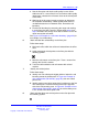
9 Using the critical points from step 7, demarcate new cell
contours, a new cell center and a new cell boundary.
See step 2 to step 5 starting on step 2 for details.
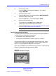
Note: Cell contour arcs must pass near the cell boundary
of adjacent cells. For an example of this, see Figure 21
"Example of deployment for cell center 1C2" (page 46).
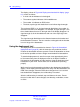
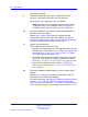
10 Demarcate additional cell contours, centers and boundaries at
the other end of the building.
Repeat step 1 to step 8 as necessary to demarcate new
cell boundaries at the other end of the building. In Figure 22
"Example of deployment for cells 1C3 and 1C4" (page 46), new
cells are formed around cell centers IC3 and IC4.
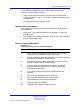
11 Identify new critical points.
These critical points must be as follows.
• adjacent to a critical point and on the opposite side of the cell
boundary area. (critical point = P11 in Figure 23 "Identify new
critical points (P11, P12, P13, P14, P15, P16, P17)" (page
47), where cell boundary area = IC2),
•
just inside of where the cell boundary meets the outside wall
(P12, P13, P14, and P15 in Figure 23 "Identify new critical
points (P11, P12, P13, P14, P15, P16, P17)" (page 47), and
• where cell boundaries meet (P16 and P17 in Figure 23
"Identify new critical points (P11, P12, P13, P14, P15, P16,
P17)" (page 47).
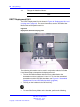
12 Demarcate additional cell boundaries to cover all areas of the
building.
Repeat step 1 to step 8 as necessary to demarcate new cell
boundaries in the middle of the building.
For more information, see Figure 24 "Contours formed by critical
points P11, P13, and P16" (page 47), Figure 25 "Cell center
1C5 formed by critical points P11, P13, and P16" (page 48), and
Figure 26 "Cell boundary 1C5 formed by critical points P11, P13,
Nortel Communication Server 1000
SIP DECT Fundamentals
NN43120-123 01.07
6 January 2009
Copyright © 2008-2009 Nortel Networks
.