Avaya Integrated Management Release 2.
Copyright 2004, Avaya Inc. All Rights Reserved Notice Every effort was made to ensure that the information in this document was complete and accurate at the time of printing. However, information is subject to change. Warranty Avaya Inc. provides a limited warranty on this product. Refer to your sales agreement to establish the terms of the limited warranty.
Electromagnetic Compatibility (EMC) Standards This product complies with and conforms to the following international EMC standards and all relevant national deviations: Limits and Methods of Measurement of Radio Interference of Information Technology Equipment, CISPR 22:1997, EN55022:1998, and AS/NZS 3548.
A plug and jack used to connect this equipment to the premises wiring and telephone network must comply with the applicable FCC Part 68 rules and requirements adopted by the ACTA. A compliant telephone cord and modular plug is provided with this product. It is designed to be connected to a compatible modular jack that is also compliant. It is recommended that repairs be performed by Avaya certified technicians. The equipment cannot be used on public coin phone service provided by the telephone company.
Table of Contents Preface . . . . . . . . . . . . . . . . . . . . . . . . . . . . . . . . . . . . . . . . . . . . . . . . . . . . . . . . 11 The Purpose of This Manual . . . . . . . . . . . . . . . . . . . . . . . . . . . . . . .11 Who Should Use This Manual . . . . . . . . . . . . . . . . . . . . . . . . . . . . .11 Organization of This Manual . . . . . . . . . . . . . . . . . . . . . . . . . . . . . .11 Chapter 1 — Network Management in Standalone Mode. . . . . . . . . . . . . . . .
Table of Contents Using Avaya Network Management Console Tables . . . . . . . . . . . .43 Using Avaya Network Management Console Help . . . . . . . . . . . . .43 Opening the Help to the Contents Page . . . . . . . . . . . . . . . . . .43 Opening the Help to a Topic of Interest . . . . . . . . . . . . . . . . . . .43 Closing Avaya Network Management Console . . . . . . . . . . . . . . . .44 Chapter 4 — Avaya Network Management Console Network Tree . . . . . . . . 45 Introduction to the Network Tree . . . .
Table of Contents Chapter 7 — Network Maps . . . . . . . . . . . . . . . . . . . . . . . . . . . . . . . . . . . . . . . 71 Introduction to Network Maps . . . . . . . . . . . . . . . . . . . . . . . . . . . . .71 Managing Network Maps . . . . . . . . . . . . . . . . . . . . . . . . . . . . . . . . .71 Creating a Network Map . . . . . . . . . . . . . . . . . . . . . . . . . . . . . .72 Opening a Network Map . . . . . . . . . . . . . . . . . . . . . . . . . . . . . .
Table of Contents Event Log Browser Toolbar . . . . . . . . . . . . . . . . . . . . . . .105 The Trap Table . . . . . . . . . . . . . . . . . . . . . . . . . . . . . . . . .106 Status Line . . . . . . . . . . . . . . . . . . . . . . . . . . . . . . . . . . . .107 The Event Configuration User Interface . . . . . . . . . . . . . . . . .107 Event Configuration Toolbar . . . . . . . . . . . . . . . . . . . . . .108 The Event Table . . . . . . . . . . . . . . . . . . . . . . . . . . . . . . . .
Table of Contents Appendix A — Network Management Menus . . . . . . . . . . . . . . . . . . . . . . . . 137 Avaya Network Management Console Menus . . . . . . . . . . . . . . . .137 Avaya Network Management Console File Menu . . . . . . . . . .137 Avaya Network Management Console Edit Menu . . . . . . . . .138 Avaya Network Management Console View Menu . . . . . . . .139 Avaya Network Management Console Actions Menu . . . . . .139 Avaya Network Management Console Tools Menu . . . . . . . .
Table of Contents 10 Avaya Network Management Console User Guide
Preface Welcome to Avaya Network Management Console in Standalone Mode. This chapter provides an introduction to the structure and assumptions of this manual. It includes the following sections: • The Purpose of This Manual - A description of the goals of this manual. • Who Should Use This Manual - The intended audience of this manual. The Purpose of This Manual This manual contains information needed to use Avaya Network Management Console in Standalone Mode efficiently and effectively.
Preface 12 • Avaya Network Management Console Introduction - An introduction to Avaya Network Management Console, including instructions on starting Avaya Network Management Console, a detailed description of Avaya Network Management Console’s user interface, and instructions on how to use Avaya Network Management Console’s on-line help.
1 Network Management in Standalone Mode This chapter provides an overview of Network Management in Standalone Mode and provides a general description of network management using Network Management in Standalone Mode. This chapter includes the following sections: • Network Management In Standalone Mode Overview - A general description of Network Management in Standalone Mode. • Network Management in Standalone Mode Terms Definitions of terms used in this documentation.
Chapter 1 Network Management In Standalone Mode Overview Network Management in Standalone Mode includes Avaya Network Management Server, and Avaya Network Management Console, an application that allows you to view the devices in your network. Avaya Network Management Console also provides a platform from which you can launch applications to manage network devices and monitor the traffic on your network.
Network Management in Standalone Mode When Avaya Network Management Server is launched, it runs a number of daemons which poll the network devices listed in the default Network Map to determine their status and updates their colors in the Avaya Network Management Console View Area. Users can manage devices or launch network-wide applications via Avaya Network Management Console.
Chapter 1 What is Avaya Network Management Server Avaya Network Management Server communicates with the devices in the network via Simple Network Management Protocol (SNMP) V1 or V3. It receives user input via Avaya Network Management Console and updates Avaya Network Management Console with information from the network devices. Avaya Network Management Server runs in the background as a Windows 2000/XP service. The server provides a central address for event reporting.
Network Management in Standalone Mode Figure 1-2. Avaya Network Management Console When a device in the Network Tree is selected, information about the selected device appears in the Network Table. You can then modify the device’s parameters. Avaya Network Management Console also provides the ability to launch applications that communicate directly with the device.
Chapter 1 Devices can be added to the current Network Map using Discovery or the Add Device dialog box. Devices in the Network Map can also be modified. All changes to the Network Map are stored in the Network File. You can maintain multiple Network Maps by saving individual maps with unique names. The Network Map whose devices are visible in Avaya Network Management Console is the current Network Map.
Network Management in Standalone Mode Network Management communicates with device agents using SNMP. Device agents can send traps to Avaya Network Management Server reporting on the status of their ports, modules, etc. The server then passes traps to the relevant managers of the device involved and updates the Event Manager. To receive traps using Network Management in Standalone Mode, network devices must be configured to send traps to the Avaya Network Management Server.
Chapter 1 Figure 1-4. Event Log Browser The Event Manager displays all of the traps sent by Avaya Network Management Server. In the Event Manager you can: • Sort the Event Log Browser by any of its fields. • Filter the traps displayed and change the severity of selected traps. • Acknowledge traps to help you remember which traps you have already seen. • Define the format of the description field. • Delete traps, signifying that the problem causing the trap was resolved.
Network Management in Standalone Mode What is Remote Access Avaya Network Management Console can be accessed remotely using a web browser. This allows you to manage your network from a computer where Network Management is not installed. When you point your browser to the Avaya Network Management Server’s IP address, a Java applet prepares your browser to communicate with Avaya Network Management Server. A welcome screen appears, followed by a password screen.
Chapter 1 22 Avaya Network Management Console User Guide
2 Avaya Network Management Server This chapter provides a detailed description of Avaya Network Management Server. It includes the following sections: • Introduction to Avaya Network Management Server - An introduction to Avaya Network Management Server. • Starting Avaya Network Management Server - Detailed instructions on how to start Avaya Network Management Server. • Stopping Avaya Network Management Server - Detailed instructions on how to shut down Avaya Network Management Server.
Chapter 2 If Avaya Network Management Server is shut down, you will need to start it manually. To manually start or stop Avaya Network Management Server, you must be logged in to Windows with Administrator privileges. When you log off the computer, Avaya Network Management Server continues running. To start Avaya Network Management Server: Select Start > Programs > Avaya > Network Manager > Start Avaya Network Management Server. Or From a command prompt type cvserver start. Or 1.
Avaya Network Management Server Stopping Avaya Network Management Server To stop Avaya Network Management Server: 1. Select Start > Programs > Avaya > Network Manager > Stop Avaya Network Management Server. Or From a command prompt type cvserver stop. A confirmation dialog box opens. 2. Click Yes. Or 1. Open Windows’ Control Panel. 2. Double-click Services. 3. Select Avaya Network Management Server from the list of services. 4. Click Stop. Avaya Network Management Server shuts down.
Chapter 2 26 Avaya Network Management Console User Guide
3 Avaya Network Management Console Introduction This chapter provides an introduction to Avaya Network Management Console. It includes the following sections: • Starting Avaya Network Management Console Instructions on how to start Avaya Network Management Console. • Avaya Network Management Console User Interface - An introduction to Avaya Network Management Console’s user interface, including instructions on how to use the toolbar buttons.
Chapter 3 To start a local session of Avaya Network Management Console from Windows: Double-click the Avaya Network Management Console icon on the Windows desktop. Or Select Start > Programs > Avaya > Network Manager > Avaya Network Management Console. Or Type cvconsole at a command prompt. Or Press CTRL + ALT + c. One of the following occurs: — If Login Mode is enabled, the Enter User Name and Passwords dialog box opens. Enter your user name and passwords and click OK.
Avaya Network Management Console Introduction • Status Bar - Displays information about the current Avaya Network Management Console session. The figure below shows the user interface, with its various parts labeled. Figure 3-1. Avaya Network Management Console Interface To resize the three main areas of the user interface, the Network Tree, the Network Table, and the Dialog Area, use the splitter bars and their arrows.
Chapter 3 Toolbar The Toolbar provides shortcuts to the main Avaya Network Management Console functions. The table below describes the buttons on the Toolbar and gives the equivalent menu options. Table 3-1. Avaya Network Management Console Toolbar Button Description Menu Item Opens the Modify dialog box for the selected object. Edit > Modify Deletes the selected object from the Network Map. Edit > Delete Cuts the selected object from a custom view to the clipboard.
Avaya Network Management Console Introduction Network Tree The Network Tree shows either a hierarchical representation of the subnets in the Network Map or a representation of the Network Map grouped by device type or logically organized by systems. You can also create customized views of the Network Map. For more information about the Network Tree, refer to Chapter 4, Avaya Network Management Console Network Tree.
Chapter 3 Using Tooltips Avaya Network Management Console includes a tooltip feature which allows you to display additional information about devices in the Network Map. To display additional information about a device, place the cursor on the device’s icon in the Network Tree or Network Table. After about one second, the tooltip appears. Figure 3-2. Avaya Network Management Console Tooltip The tooltip provides the following information about the device: • Name - The Best Name of the device.
Avaya Network Management Console Introduction The following are the assigned permissions at login: • No read/write console exists - read/write permission is automatically assigned to your console. • Read/Write console currently exists - your console is assigned read only permission. * Note: Only one console may have read/write permission at any given time. If your console is opened with read only permission, you can request write permission.
Chapter 3 4. If the console that currently has write permission refuses your request, the Write Permission Refused dialog box opens. Click OK to proceed with read only permission. If your console currently has read/write permission and a request is made for write permission by another console, the Remote Request dialog box opens. To release read/write permission in response to another console’s request: 1. Click OK to release write permission to the requesting console. 2.
Avaya Network Management Console Introduction SNMP Access Parameters Using the SNMP Access parameters page of the Avaya Network Management Console Options dialog box, you can set basic SNMP parameters for specific devices, ranges of devices, and all unspecified devices. Avaya Network Management Server recognizes the following SNMP protocols: V1 and V3. SNMP access parameters for SNMP V1 include read and write community properties.
Chapter 3 Figure 3-3. Avaya Network Management Console Options Dialog Box Default Page To add a new set of SNMP default parameters to the list: 1. Click Add. A new row opens in the Default table. 2. Select V1 or V3 (login mode only) from the Type pull-down listbox. 3. If you selected V1 in the Type field, enter read and write community values in their respective fields. 4. If you selected V3 in the Type field, select a user name from the User pull-down listbox.
Avaya Network Management Console Introduction To edit entries in the in the Default table: 1. Click the field you want to edit. 2. Edit the information in the field. 3. Click Apply. The changes are saved in the table. To remove a range from the Default table: 1. Select a row. 2. Click Delete. 3. Click Apply. The range is deleted from the Default table. Setting SNMP Access Parameters for IP Ranges The IP Wildcard page enables you to configure SNMP access parameters for ranges of devices.
Chapter 3 2. Select V1 or V3 (login mode only) from the Type pull-down listbox. 3. Enter an IP Wildcard in the IP Wildcard field. 4. If you selected V1 in the Type field, enter read and write community values in their respective fields. 5. If you selected V3 in the Type field, select a user name from the User pull-down listbox. The user name must have been defined in the User Administration window. For more information, refer to the Network Management User Administration User’s Guide. 6.
Avaya Network Management Console Introduction Setting Specific IP Parameters To view SNMP access parameters for specific devices, click the Specific IP’s tab on the SNMP Access page of the Avaya Network Management Console Options dialog box. The Specific IP’s page appears. Figure 3-5. Avaya Network Management Console Options Dialog Box Specific IP’s Page To add a new device to the list: 1. Click Add. A new row opens in the Specific IP’s table. 2.
Chapter 3 To remove a device from the Specific IP’s table: 1. Select a device. 2. Click Delete. 3. Click Apply. The device is deleted from the Specific IP’s table.
Avaya Network Management Console Introduction 4. Enter a number in the Timeout field. This is the number of milliseconds Avaya Network Management Server will wait for a response when PINGing a node before declaring it to be unreachable. 5. Enter a number in the Interval field and select either minutes or seconds. This is the amount of time between PINGs. 6. To return the values to the default settings, click Default. 7. Click Apply. The network is configured with the new connectivity polling parameters.
Chapter 3 Setting Read/Write Defaults The Read/Write Defaults page of the Avaya Network Management Console Options dialog box enables you to set the default read/write permissions. To set read/write defaults: 1. Click the Read/Write Defaults tab at the top of the Avaya Network Management Console Options dialog box. The Read/Write Defaults page appears. Figure 3-8. Avaya Network Management Console Options Dialog Box Read/Write Defaults Page 2.
Avaya Network Management Console Introduction Using Avaya Network Management Console Tables Avaya Network Management Console informs you of the status of each row in a table. The following table shows symbols that appear at the start of a row, with their corresponding explanations. Table 3-2. Row Status Symbol Explanation The row is a new entry. The row is to be deleted. The row has been modified.
Chapter 3 Closing Avaya Network Management Console To close Avaya Network Management Console, select File > Exit. Avaya Network Management Console closes.
4 Avaya Network Management Console Network Tree This chapter provides a detailed description of the Network Tree. It includes the following sections: • Introduction to the Network Tree - An introduction to the Network Tree. • Using the Network Tree - A detailed description of the Network Tree and its hierarchy, and instructions on how to customize the Network Tree. • Printing the Network Tree - Instructions on how to print the Network Tree.
Chapter 4 The left side of the user interface is the Network Tree. This provides a hierarchical view of the network. The right side of the user interface contains the Network Table. Together, these views provide details about specific elements in the network. When an element in the tree is selected, the elements immediately below the selected element appear in the Network Table. Elements in the Network Table are accompanied by fields providing details about the elements.
Avaya Network Management Console Network Tree The Subnet View The Subnet View tree shows a hierarchical view of the subnets in the network. The Subnet View of the network contains the following levels: 1. My Network - An icon representing the entire network. When the icon representing the network is selected, all subnets appear in the Network Table. 2. Subnets - Icons representing the subnets in the network.
Chapter 4 The System View The System View tree shows a hierarchical view of the voice devices in the network. The tree is organized with the voice device controllers on the higher levels and the controlled voice devices on lower levels. Figure 4-1. System View The root of the System View tree is My Network. This icon represents all voice devices in the network. The root splits into three branches - CM Servers (Communication Manager Media Servers), CC Servers (Converged Communications Servers), and Other.
Avaya Network Management Console Network Tree The CC Servers branch splits based on Converged Communications Servers. Each discovered CC Server displays its own branch, on which a 46xx branch appears if 46xx series IP phones are discovered. The 46xx branch shows all discovered 46xx series IP phones associated with the CC Server. The Other branch splits into three. The S8100 branch displays S8100 Devices in the network.
Chapter 4 Creating Custom Views To create a custom view: 1. Select File > View > New. The New View dialog box opens. Figure 4-2. New View Dialog Box 2. Enter a name for the view in the View Name field. * Note: View names cannot contain periods. 3. Enter a description of the view in the Description field. 4. Click Apply. The view is added to Avaya Network Management Console with the top level My Network. All devices in the network are added to a branch labeled Unassigned.
Avaya Network Management Console Network Tree 5. Click Apply. The view is modified. Deleting Custom Views To delete a custom view of the network: 1. Click the View Tab associated with the custom view you want to modify. 2. Select Edit > Delete View. A confirmation dialog box opens. 3. Click Yes. The custom view is deleted. Adding Branches in Custom Views You can add branches to a custom view of the network and populate the branches with devices or nested branches.
Chapter 4 — To remove devices from the Members list: a. Select the devices you want to remove from the branch in the Members list. b. Click . The devices are removed from the Members list. 6. Click Apply. The branch and its devices are added to the selected part of the tree. Modifying Branches in Custom Views You can add and remove devices from branches in a custom view of the network. To modify a branch of a custom view of the network: 1. Select the branch you want to modify in the Network Tree.
Avaya Network Management Console Network Tree * Note: The Unassigned branch cannot be deleted. 2. Select Edit > Delete. A confirmation dialog box opens. 3. Click Yes. The branch is deleted, and all its devices appear in the Unassigned list. Printing the Network Tree To print the current view of the Network Map, select File > Print. The current view of the Network Map is printed. To view a preview of the printed Network Map, select File > Print Preview. The preview of the Network Tree opens. Figure 4-6.
Chapter 4 Searching the Tree Avaya Network Management Console enables you to search the Network Map for specific elements. To search the Network Map: 1. Click . Or Select Edit > Find. The Find dialog box opens. Figure 4-7. Find Dialog Box 2. Select one of the Find Options option buttons. 3. Enter the device’s name (or part of it), IP address, or MAC address in the Find What field. 4. Click Find. The element you searched for appears highlighted in the tree.
5 Avaya Network Management Console Network Table This chapter provides a detailed description of the Network Table. It includes the following sections: • Using the Network Table - A detailed description of the information in the Network Table. • Managing Objects - Instructions on how to manage and unmanage objects in the Network Map. • Manually Adding Devices - Instructions on how to add devices to the Network Map. • Modifying Devices - Instructions on how to modify device parameters.
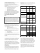
Chapter 5 Network Table Fields The following table lists the columns in the Network Table when the root of the Network Tree is selected in Subnet View. Table 5-1. Network Table - Subnets Field Description Name IP address of the subnet. Status The status of the subnet. No. of Devices The number of registered devices in the subnet. The following table lists the columns in the Network Table when the root of the Network Tree is selected in Device Type View. Table 5-2.
Avaya Network Management Console Network Table The following table lists the columns in the Network Table when a device is selected in the Network Tree. Table 5-4. Network Table - Interfaces Field Description IP Address The IP address of the interface. Interface Status The status of the interface. MAC Address The MAC address of the device. Subnet Mask The subnet mask of the device’s IP address. Interface Number The number of the interface.
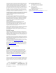
Chapter 5 The following diagram outlines the method used by Network Management to determine the color of a device in the Network Table. Figure 5-1. Device Coloring Method Is the device managed? Yes No Off-White Unmanaged Is there at least one reachable IP interface? Yes No The Agent Status is unreachable or there is no Agent interface? Yes No Are all interfaces up? Yes Green Okay Red Fatal No Yellow Warning The Agent’s status determines the color and status of the device.
Avaya Network Management Console Network Table To unmanage an object: 1. Select the object in the Network Table. 2. Select Edit > Unmanage. The selected object is unmanaged. To manage an unmanaged object: 1. Select the object in the Network Table. 2. Select Edit > Manage. The selected object is managed. Manually Adding Devices You can manually add devices to the Network Map. To manually add a device to the current Network Map: 1. Select File > New > Device. The Add Device dialog box opens. Figure 5-2.
Chapter 5 Modifying Devices To modify the device or SNMP parameters of a device in the current Network Map: 1. Select a device. 2. Select Edit > Modify. The Modify Device Parameters dialog box opens with the selected device’s parameters. Figure 5-3. Modify Device Parameters Dialog Box 3. Modify the parameters in the dialog box. 4. To edit the device’s SNMP parameters, click the SNMP Access tab. 5. Enter the SNMP parameters. 6. Click Apply. The parameters are modified.
Avaya Network Management Console Network Table Table 5-6. Device Parameters (Continued) Parameter Description Device Name The name or best name of the device. Device Type Type of device. Possible types are: • Auto Discover - Avaya Network Management Server polls the device to determine the device type. • Avaya Device - Where Avaya Device is the name of an Avaya Device. • Generic SNMP - For other SNMP Devices. • Generic IP - For IP Devices that do not use SNMP.
Chapter 5 Deleting Devices To delete selected devices from the current Network Map: 1. Select a device. — To select more than one device, press CTRL while selecting additional devices. 2. Select Edit > Delete. A confirmation dialog box appears. 3. Click Yes. The selected device is deleted from the Network Map.
6 Avaya Network Management Console Application Launcher This chapter provides detailed instructions on launching applications from Avaya Network Management Console. It includes the following sections: • Launching Device Applications - Instructions on launching device-specific applications from Avaya Network Management Console. • Launching Network-wide Applications - Instructions on launching network-wide applications from Avaya Network Management Console.
Chapter 6 Device Manager To launch the Device Manager for a managed device in the current Network Map: 1. Select the device. 2. Click . Or Select Tools > Avaya Device Manager. Or Double-click the device. The Device Manager for the selected device opens. * Note: When running a remote session of Avaya Network Management Console, Device Manager can only be launched for devices that can be managed remotely. Telnet Telnet can be used to access the Command Line Interface (CLI) of a network device.
Avaya Network Management Console Application Launcher To launch a Web Session: 1. Select a device that supports Web Sessions. 2. Click . Or Select Tools > Web. A Web Session opens to the device. PING The PING application enables you to PING devices from within Avaya Network Management Console. If you are having a problem communicating with the device via SNMP, try to ping the device.
Chapter 6 2. Select Tools > Avaya Site Administration. Or Double-click an appropriate managed telephony device. — If you selected a Communication Manager Media Server, ASA connects to the device and opens the appropriate form for the server. — If you selected an IP phone, ASA connects to the Communication Manager Media Server controlling the selected phone and opens the appropriate form for the phone’s extension.
Avaya Network Management Console Application Launcher Avaya MultiSite Administration Avaya MultiSite Administration is a system management tool designed for configuration of Communication Manager Media Servers and Media Gateways, and upgraded DEFINITY® servers. * Note: Avaya MultiSite Administration is part of Avaya Integrated Management. To launch the main Avaya MultiSite Administration window: Select Tools > Avaya MultiSite Administration with no device selected.
Chapter 6 Avaya VAL Manager Avaya VAL Manager is a system management tool designed for Voice Announcements over LAN (VAL) on Avaya switches that support VAL. * Note: Avaya VAL Manager is part of Avaya Integrated Management. To launch the main Avaya VAL Manager window, select Tools > Avaya VAL Manager with no device selected. The main Avaya VAL Manager window opens. To launch Avaya VAL Manager on an appropriate VAL board: 1. Select an appropriate VAL board. 2. Select Tools > Avaya VAL Manager.
Avaya Network Management Console Application Launcher Extreme EPICenter Extreme EPICenter is a device management tool used to manage Extreme switches connected to your network. Currently supported switches are: • Alpine 3804 • Alpine 3808 • Black Diamond 6804 • Black Diamond 6808 • Summit 200-24 • Summit 200-48 • Summit 300-24 • Summit 300-48 • Summit 400-48t To launch Extreme EPICenter on a supported Extreme switch: 1. Select a supported Extreme switch. 2.
Chapter 6 Launching Network-wide Applications To launch a network-wide application, select Tools > Application Name, where Application Name is the name of the network-wide application you want to run. The network-wide application opens. * Note: Avaya SMON Manager is only available with the purchase of an SMON license. For more information on SMON licenses, refer to Appendix B, Setting up the SMON License in the Avaya SMON Manager User Guide.
7 Network Maps This chapter provides a detailed description of Network Maps in Avaya Network Management Console. It includes the following sections: • Introduction to Network Maps - An introduction to Network Maps. • Managing Network Maps - Instructions on how to create, open, save, and print Network Maps. • Importing Devices into the Network Map - Detailed instructions on importing devices into the Network Map.
Chapter 7 Creating a Network Map To create a new Network Map: 1. Select File > New > Map. The Create New Map dialog box opens. Figure 7-1. Create New Map Dialog Box 2. Enter a name for the file in the New map name field. 3. Click OK. A new Network Map is created. 4. Add subnets and devices to the Network Map using one of the following methods: — Discovery - For more information, refer to “Discovering Subnets and Nodes” on page 92.
Network Maps Opening a Network Map To open a Network Map: 1. Select File > Open > Map. The Open Map dialog box opens. Figure 7-2. Open Map Dialog Box 2. Select a Network Map from the list. 3. Click Open. The selected Network Map opens. Saving a Network Map to a Different Name To save a Network Map to a different Name: 1. Select File > Save As. The Save Map As dialog box opens. Figure 7-3. Save Map As Dialog Box 2. Enter a name for the file in the Map Name field. 3. Click Save As.
Chapter 7 Printing a Network Map To print a Network Map, select File > Print. The Network Map is printed. Importing Devices into the Network Map Devices can be imported from a text file into the Network Map. The information for each device must be on a single line, with the various information fields for the device separated by commas. This file is referred to as a Comma Separated Value (CSV) file. The following is an example of rows in a CSV file: .1.3.6.1.4.1.23.1.6.4.11,149.49.32.253,149.49.48.215,255.
Network Maps Exporting the Network Map The current Network Map can be exported to CSV files for use with applications, such as Microsoft Excel. For information on the structure of CSV files of exported Network Maps, refer to “CSV File Structure” on page 75. To export devices from the current Network Map to a CSV file: 1. Select File > Export > Map. A standard file browser opens. 2. Browse to the directory to which you want to save the file. 3. Enter a name for the CSV file in the Name field. 4. Click Save.
Chapter 7 Table 7-1. CSV Network File Syntax (Continued) 76 Field Description Retries The number of times an application will poll the device without receiving a response before timing out. Timeouts The number of milliseconds an application will poll the device without receiving a response before timing out.
8 Introduction to the Discovery Window This chapter provides an introduction to the Discovery window. It includes the following sections: • Opening the Discovery Window - Instructions on how to open the Discovery window. • The Discovery User Interface - A description of the Discovery window. • Closing the Discovery Window - Instructions on how to close the Discovery window. Opening the Discovery Window To open the Discovery window: Click . Or Select Actions > Discovery. The Discovery window opens.
Chapter 8 The Discovery User Interface The Discovery user interface consists of the following elements: 78 • Discovery Menu Bar - Menus for accessing Discovery functions. For more information on Discovery menus, refer to Appendix A, Network Management Menus. • Discovery Toolbar - Toolbar buttons for accessing Discovery functions. • Subnets Table - A table of subnets listed in the Network View and discovered subnets. • Discovery Dialog Area - A resizeable window where all dialog boxes open.
Introduction to the Discovery Window Discovery Toolbar The table below describes the buttons on the Discovery Toolbar and gives the equivalent menu options. Table 8-1. Discovery Toolbar Button Description Menu Item Saves the current Discovery settings. File > Save As Opens the Discovery Options dialog box. File > Options Starts a Discovery based on the default routers of the management station and the contents and settings of the Subnet Table. Actions > Discover Stops a Discovery process.
Chapter 8 Subnets Table The Subnets Table contains a list of subnets from the following sources: • The current Network Map. • Subnets added to the Subnets Table manually by the user. • Subnets found in a Discovery. The following table provides a list of the fields in the Subnets Table and provides an explanation of each field. Table 8-2. Subnets Table Fields Field Name Description Subnet The IP address of the subnet. Mask The subnet mask. Router The IP address of the subnet’s router.
Introduction to the Discovery Window Discovery Dialog Area The area at the right of the Subnets Table is where all dialog boxes open. This area can be resized by dragging the vertical splitter bar with the mouse. When a dialog box opens, it replaces the current dialog box open in the Dialog Area. When no dialog box is open, the Dialog Area disappears and the Subnets Table expands to take its place. Discovery Log Area The area under the Subnets Table is where the Discovery Log opens.
Chapter 8 82 Avaya Network Management Console User Guide
9 Discovering Your Network This chapter provides detailed instructions on how to use Avaya Network Management Console’s Discovery feature. It includes the following sections: • Setting Discovery Options - Instructions on how to set Discovery options. • Discovering Subnets and Nodes - Instructions on how to discover the subnets and devices in your network.
Chapter 9 To configure Discovery options: Click in the Discovery toolbar. Or Select File > Options in the Discovery menu bar. The Discovery Options dialog box opens. Configuring Discovery Method and Range To configure the method and range of Discovery: 1. Click the IP Discovery tab at the top of the Discovery Options dialog box. The IP Discovery page of the Discovery Options dialog box appears. Figure 9-1. IP Discovery Options Dialog Box 2. Configure the IP Discovery options. 3. Click Apply.
Discovering Your Network The following table provides a list of the fields in the IP Discovery page of the Discovery Options dialog box. Table 9-1. IP Discovery Options Field Name Description Default gateway for the CVS host The IP address of the default gateway used for Discovery. By default, this is the Gateway IP Address for the Network Management management station. Maximum subnet size to ping The mask applied to the subnet address to determine the number of IP addresses in the subnet.
Chapter 9 Configuring Discovery’s Naming Method To configure the method Discovery uses for selecting names for discovered nodes: 1. Click the Names Discovery tab at the top of the Discovery Options dialog box. The Names Discovery page of the Discovery Options dialog box appears. Figure 9-2. Names Discovery Options Dialog Box 2. Configure the Names Discovery options. 3. Click Apply. Names Discovery Options are configured.
Discovering Your Network The following table provides a list of the fields in the Names Discovery page of the Discovery Options dialog box. Table 9-2. Names Discovery Options Field Name Description Update names for existing entries This determines whether Discovery updates the names for nodes already listed in the Network Map. Possible states are: • Update - Discovery updates the names of all discovered nodes. User defined names will be replaced by the best name discovered.
Chapter 9 Table 9-2. Names Discovery Options (Continued) Field Name Description Select best name sequence This determines the order Discovery uses to define names for discovered nodes. Discovery can use the following sources to determine the name of a node: • IP - The IP address of the node. • SNMP system name - The value assigned to the device’s sysName MIB. • Name Service - The name assigned to the node via a Name Service application.
Discovering Your Network Selecting Device Types to Discover To configure the types of devices Discovery will find: 1. Click the Discovered Types tab at the top of the Discovery Options dialog box. The Discovered Types page of the Discovery Options dialog box appears. Figure 9-3. Discovered Types Options Dialog Box 2. Configure the Discovered Types options. 3. Click OK. Discovered Types Options are configured. The Discovered Types page of the Discovery Options dialog box has two listboxes.
Chapter 9 * Note: Avaya Network Management Console supports discovery of the following Avaya IP phones: Avaya 4601, Avaya 4610, Avaya 4690. * Note: Avaya Network Management Console supports discovery of the following Extreme switches: Alpine 3804, Alpine 3808, Black Diamond 6804, Black Diamond 6808, Summit 200-24, Summit 200-48, Summit 300-24, Summit 300-48, Summit 400-48t. * Note: Avaya Network Management Console supports discovery of Avaya Converged Communications Servers.
Discovering Your Network 2. Configure the Discovery Scheduler options. 3. Click Apply. Discovery Scheduler parameters are configured. * Note: At different stages while Network Discovery is running, certain operations of Network Management Console are disabled. The following table provides a list of the fields in the Discovery Scheduler dialog box. Table 9-3. Discovery Scheduler Field Name Description Enable Scheduler When checked, the Discovery Scheduler is enabled.
Chapter 9 Discovering Subnets and Nodes The Discovery function can be used to discover all the subnets and nodes in your network, or search for nodes on specific subnets. For information on configuring Discovery Options, refer to “Setting Discovery Options” on page 83. Problems during Discovery are reported in the Discovery Log. For more information, refer to “Using the Discovery Log” on page 98.
Discovering Your Network To stop the Discovery, click Stop. A confirmation dialog box opens. Click Yes. Discovery finishes adding the current node to the table and stops. When the Discovery finishes, the Subnets Table will contain a list of the subnets discovered in your network. 4. Click in the Discovery toolbar. Or Select File > Update Map in the Discovery menu bar. The Network Map is updated with the results of the Discovery and saved to its corresponding Network File.
Chapter 9 To unselect subnets upon which Discovery will search for nodes: 1. Uncheck the Discover checkbox for each subnet upon which you do not want to discover nodes. Or 1. In the Subnets Table, select the subnets upon which you do not want to discover nodes. To unselect more than one subnet: — Press SHIFT and select the last subnet in a contiguous selection. — Press CTRL and select additional subnets for a non-contiguous selection. 2. Click in the Discovery toolbar. Or Select Edit > Unselect.
Discovering Your Network To update the Network Map with the updated information: Click in the Discovery toolbar. Or Select File > Update Map in the Discovery menu bar. The Network Map is updated with the results of the Discovery and saved to its corresponding Network File. After the Network Map is updated, System View Discovery runs automatically and the Network Map is updated with the System View tab. Manually Adding Subnets To manually add a subnet to the Subnets Table: 1.
Chapter 9 4. Click in the Discovery toolbar. Or Select File > Update Map in the Discovery menu bar. The Network Map is updated with the results of the Discovery and saved to its corresponding Network File. After the Network Map is updated, System View Discovery runs automatically and the Network Map is updated with the System View tab. Modifying Subnets To modify a subnet in the current Network Map: 1. Select a subnet in the Subnets Table. 2. Click in the Discovery toolbar.
Discovering Your Network 5. Click in the Discovery toolbar. Or Select File > Update Map in the Discovery menu bar. The Network File is updated with the information in the Network Map. After the Network Map is updated, System View Discovery runs automatically and the Network Map is updated with the System View tab. Subnet Parameters The following table provides a list of the parameters in the Add Subnet and Modify Subnet dialog boxes. Table 9-4.
Chapter 9 Deleting Subnets To delete a subnet from the Subnets Table: 1. Select a subnet in the Subnets Table. — To select multiple subnets, press CTRL while selecting additional subnets. 2. Click in the Discovery toolbar. Or Select Edit > Delete in the Discovery menu bar. A confirmation dialog box opens. 3. Click Yes. The selected subnets are deleted from the Subnets Table. Using the Discovery Log The progress of the Discovery process is reported in the Discovery Log.
Discovering Your Network Configuring Router Access Parameters You can configure the SNMP parameters for a router that Discovery could not access. This may allow Discovery to search the router’s subnets for nodes. To view router access parameters, click the router’s access error message in the Discovery Log. The Router Access Configuration dialog box opens. Figure 9-10.
Chapter 9 Table 9-5. Router Access Configuration Parameters (Continued) Field Name Description Retries The number of times Discovery will ping the router with no response before giving up. Timeout (milliseconds) The amount of time (in milliseconds) Discovery will ping the router with no response before timing out. To change the router access configuration and retry discovering nodes on the subnet: 1. Change some of the router access configuration parameters. 2. Click OK.
Discovering Your Network 2. Confirm your selection. The Discovery Log is cleared. Manually Discovering System View To manually discover the System View: Select Actions> System View Discovery in the Console menu bar. System View Discovery is performed and the Network Map is updated. Using the System View Log The progress of the most recent System View Discovery process is reported in the System View Log. To view the System View Log, select View > System View Log in the Console menu bar.
Chapter 9 102 Avaya Network Management Console User Guide
10 Introduction to the Event Manager This chapter provides a detailed description of the Event Manager, and includes the following sections: • Event Manager Overview - An overview of the Event Manager. • Viewing the Event Manager - Detailed instructions on how to view the Event Manager. • The Event Manager User Interface - A description of the Event Log Browser, Event Configuration window, and Action List window. • Closing the Event Manager - Instructions on how to close the Event Manager.
Chapter 10 Viewing the Event Manager To view the Event Manager: Click . Or Select Actions > Event Manager. The Event Manager opens showing the Event Log Browser.
Introduction to the Event Manager Figure 10-1. Event Log Browser User Interface Event Log Browser Toolbar The table below describes the buttons on the Event Log Browser Toolbar and gives the equivalent menu options. Table 10-1. Event Log Browser Toolbar Button Description Menu Item Deletes the selected traps. Edit > Delete Marks the selected traps as acknowledged. Edit > Acknowledge Marks the selected traps as unacknowledged.
Chapter 10 The Trap Table By default, the Trap Table lists the traps sent to Avaya Network Management Server in the order in which they were sent. The information displayed in the Trap Table in the However, you can sort the Trap Table by any of its fields. To sort the Trap Table by one of its fields, click the field’s column header. To reverse the sort order, click the column header again.
Introduction to the Event Manager To locate the device from which an event was sent, double-click the event in the Trap table and the device will be highlighted in the SNMP Console tree. Status Line The Event Log Browser’s Status Line displays the number of traps in the Event Log Browser. This number includes traps that are not currently displayed in the Trap Table. In addition, the Status Line displays the current filtering options.
Chapter 10 Figure 10-2. Event Configuration User Interface Event Configuration Toolbar The table below describes the buttons on the Event Configuration toolbar and gives the equivalent menu options. Table 10-3. Event Configuration Toolbar Button Description Menu Item Opens the Modify Trap dialog box for the selected network event. Edit > Modify Event Opens the Action List window. Tools > Action List Opens the Event Forwarding dialog box. Tools > Event Forwarding Opens context-sensitive help.
Introduction to the Event Manager The Event Table The Event Table lists network events in a collapsible tree. Each event category can be expanded or collapsed by clicking the handle next to the category. The following table provides a list of the fields in the Event Table and an explanation of each field. Table 10-4. Event Table Fields Field Description Name The name of the event or event category. Category The category of the event.
Chapter 10 Assign Action Form Area The Assign Action Form Area provides a dialog box for assigning predefined actions to specific events. The following table provides a list of the fields in the Assign Action Form and an explanation of each field. Table 10-5. Assign Action Form Fields Field Description Actions The action assigned to the selected event. Possible actions are: • None - No action is assigned to the selected event.
Introduction to the Event Manager Table 10-6. Event Configuration Form Fields (Continued) Field Description Severity The severity of the selected event: • Normal • Warning • Minor • Major • Critical Enable Forward If checked, the event is forwarded to selected stations. If unchecked, the event is not forwarded, unless you forward all events. Format The format in which the event will be displayed in the description field of the Event Log Browser.
Chapter 10 The Action List User Interface The Action List user interface consists of the following elements: • Menu Bar - Menus for accessing Action List functions. For more information on Action List menus, refer to Appendix A, Network Management Menus. • Action List Toolbar - Toolbar buttons for accessing Action List functions. • The Action Table - A table providing a list of configured responses to network events. • Action Form Area - An area where all dialog boxes appear. Figure 10-3.
Introduction to the Event Manager Table 10-7. Action List Toolbar (Continued) Button Description Menu Item Adds a new action to the Action List. Edit > Add Opens the Modify Action dialog box for the selected action. Edit > Modify Deletes the selected action. Edit > Delete Opens context-sensitive help. Help > Help on When you place the cursor on a toolbar button for one second, a label appears with the name of the button. The Action Table The Action Table lists configured actions.
Chapter 10 Action Form Area The Action Form Area is where the Add Action and Modify Action dialog boxes open. For information on the fields in the Add Action and Modify Action dialog boxes, refer to “Action Fields” on page 126. Closing the Event Manager To close the Event Manager, select File > Exit. The Event Manager closes.
11 Managing Events This chapter provides instructions on using the Event Manager. It includes the following sections: • Managing Traps - Detailed instructions on how to filter, acknowledge, delete, edit, save, and archive traps. • Defining Actions - Detailed instructions on how to define actions. • Configuring Events - Detailed instructions on how to assign defined actions to network events.
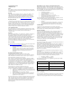
Chapter 11 Trap Log Options The Trap Log can hold up to 10,000 traps. When this limit is reached, traps must be removed from the Trap Log to provide room for new traps. You can configure Network Management to either discard old traps or archive them. * Note: By default, when the Trap Log holds 10,000 traps, the oldest 1,000 traps are discarded. * Note: Archived traps are appended to the event archive. To configure the method Network Management uses to clean up the Trap Log: 1. Select File > Options.
Managing Events 4. Click Apply. The clean up method for the Trap Log is configured. Whenever the Trap Log contains 10,000 events, this method will be used to remove the specified number of events from the Trap Log. * Note: If you specify a CSV file for the trap archive and the file is open when traps need to be archived, a new file is created containing all of the traps in the old archive. Archiving continues using the new file.
Chapter 11 1. Select View > Filter > Severity Filter. The Severity Filter dialog box opens. Figure 11-2. Severity Filter Dialog Box 2. Check the checkboxes next to the severity levels of the traps you want displayed in the Trap Table. 3. Click Apply. Only traps of the checked severity levels are displayed in the Trap Table. Filtering By IP Address To view only traps from a specific IP address: 1. Click . The cursor changes to a hand. 2. Click on the From column of a trap from the desired device.
Managing Events Filtering By Device Type To view only traps from a specific device type: 1. Click . The cursor changes to a hand. 2. Click on the Device Type column of a trap from the desired device type. Only traps from devices of the selected device type are displayed in the Trap Table. Or 1. Select View > Filter > Device Type Filter. The Device Type Filter dialog box opens. Figure 11-4. Device Type Filter Dialog Box 2. Select device types from the listbox. 3. Click Apply.
Chapter 11 2. Check the checkboxes next to the Acknowledgement statuses of the traps you want displayed in the Trap Table. 3. Click Apply. Only traps with the checked Acknowledgement statuses are displayed in the Trap Table. Viewing All Traps To cancel the current filtering options and view all traps in the Trap Table, select View > Filter > No Filter. All traps are displayed in the Trap Table.
Managing Events 2. Click . Or Select Edit > UnAcknowledge. Or Click the Acknowledge Icon field in an acknowledged trap. The trap is unmarked. Deleting Traps It is important to delete old traps from the Trap Table. This prevents the Event Manager from becoming unwieldy and allows you to focus on current network events. To delete a trap: 1. Select a trap. — To select multiple traps, press CTRL while clicking on additional traps. — To select all traps, select Edit > Select All. 2. Click .
Chapter 11 2. Select Edit > Change Severity > Change severity to Severity level, where Severity level is the severity level for the trap. Or Select a severity level from the trap’s Severity column. The trap’s severity level is changed. Saving the Trap Table The Trap Table can be saved to a file. The file can be in one of the following formats: • Comma Separated Values (CSV) - As a text file with the columns in each row separated by commas. • XML - As an XML file. To save the Trap Table to a file: 1.
Managing Events Defining Actions This topic provides instructions on defining actions and includes the following sections: • Actions Overview - An overview of trap actions in Avaya Network Management Console. • Adding Actions - Instructions on how to add actions to the Action List. • Modifying Actions - Instructions on how to modify actions. • Action Fields - A description of each of the fields in the Add/Modify Action dialog box.
Chapter 11 Adding Actions To add an action to the Action List: 1. Click . Or Select Edit > Add Action. The Add Action dialog box opens. Figure 11-7. Add Action Dialog Box 2. Define the action using the Add Action dialog box fields. For information on the fields in the Add Action dialog box, refer to “Action Fields” on page 126. 3. To test the new action, click Test Actions. The defined actions occur. 4. Click Apply. The action is added to the Action List.
Managing Events Modifying Actions To modify an action in the Action List: 1. Select an action in the Action List. 2. Click . Or Select Edit > Modify Action. The Modify Action dialog box opens. Figure 11-8. Modify Action Dialog Box 3. Edit the action using the Add Action dialog box. For information on the fields in the Modify Action dialog box, refer to “Action Fields” on page 126. 4. To test the modified action, click Test Actions. The defined actions occur. 5. Click Apply.
Chapter 11 Action Fields The following topics are described in this section: • Action Scripts • Action Audio Files The following table provides a list of the fields in the Add Action and Modify Action dialog boxes and an explanation of each field. Table 11-1. Action Fields 126 Field Description Action Name The name of the defined action. Popup message The state of the checkbox determines whether the action includes a pop-up message. The textbox contains the text of the pop-up message.
Managing Events Action Scripts You can include any executable file in an action. Valid executable files are operating system dependant. For example, on a computer running Windows, BAT, COM, and EXE files are executables. In addition, up to four variable command line parameters can be included in the command. The following table provides a list of the command line variables and their descriptions. Table 11-2.
Chapter 11 For example, the command print_report printer:BOSTON $A $e $f, may send the command print_report printer:BOSTON 213.21.70.142 Major "Bus 10 internal clock fault" to your computer. * Note: Network Management is not responsible for validating any assigned scripts or ensuring that they can receive command line parameters. Action Audio Files You can select any audio file recognized by your computer for inclusion in an action. The file will be played by its associated application.
Managing Events Action Options If you define actions that include e-mails, you must configure Avaya Network Management Console to use an appropriate SMTP server. In addition, you should specify an e-mail address as the sender of the e-mail. To define e-mail settings: 1. Select Tools > Options. The Action List Options dialog box opens. Figure 11-10. Action List Options Dialog Box 2. Enter your SMTP server in the SMTP server field. 3.
Chapter 11 Configuring Events Some network events are so important, that the reporting of the event in the Event Log Browser is not sufficient. The Event Configuration window allows you to configure additional notification methods for important traps. In addition, you can configure event forwarding from the Event Configuration window.
Managing Events Figure 11-11. Action Definition Dialog Box 4. Click Select Action. To unassign an action, click None, and continue with step 7. 5. Select a defined action from the pull-down listbox. For more information on defining actions, refer to “Defining Actions” on page 123. 6. Select source devices for the action. The Event Action is defined for only the devices in the Members listbox or for all devices. To define the action for all network devices, check the Add All Sources checkbox.
Chapter 11 8. Select a severity from the Severity pull-down listbox. 9. If you want to enable event forwarding for the event, check the Enable Event Forward checkbox. The event will be forwarded to the IP addresses listed in the Event Forwarding Options dialog box. To prevent the event from being forwarded, clear the Enable Event Forward checkbox. The event will not be forwarded unless the All button is selected in the Event Forwarding Options dialog box. 10.
Managing Events To open the Event Forwarding Options dialog box: Click . Or Select Tools > Event Forward. The Event Forwarding Options dialog box opens. Figure 11-12. Event Forwarding Options Dialog Box To close the Event Forwarding dialog box, click Cancel.
Chapter 11 Event Forwarding Sources To configure event forwarding sources: 1. Do one of the following: — To forward all events, check the Forwarding All Events checkbox. — To forward only specific events, uncheck the Forwarding All Events checkbox. Only events configured with the Enable Event Forward checkbox in the Action Definition dialog box are forwarded. For more information, refer to “Action Options” on page 129. 2. Select the severity level of the alarm: Critical, Major, Minor, Warning, Info.
12 Remote Access This chapter provides information about Network Management’s remote access capabilities and security issues. It includes the following sections: • Introduction to Remote Access - An introduction to remote access issues. • Remote Access and Security - Information about security issues when running a remote session of Network Management. • Starting a Remote Session - Detailed instructions on how to start a remote session of Avaya Network Management Console.
Chapter 12 Starting a Remote Session To start a remote session of Avaya Network Management Console: 1. Point your web browser to http://IP_Address/nm, where IP_Address is the IP address of the Avaya Network Management Server. The Avaya Network Management Console Remote Entry Page opens. Figure 12-1. Network Management 2. Click Open Avaya Network Management Console. The Java applet starts. 3. A window opens requesting your user name and password. 4. Enter your user name and password, and click OK.
A Network Management Menus This appendix gives the full structure of the menus in Network Management. These menus include: • Avaya Network Management Console Menus • Discovery Menus • Event Log Browser Menus • Event Configuration Menus • Action List Menus Avaya Network Management Console Menus This section gives the full structure of the menus in Avaya Network Management Console.
Appendix A Table A-1. Avaya Network Management Console - File Menu Item Description Export Exports device information from the current Network Map to a CSV file. Print Prints the current Network Map. Print Preview Opens the Print Preview window for the Network Map. Options Opens the Options dialog box. Exit Closes Avaya Network Management Console. Avaya Network Management Console Edit Menu Table A-2.
Network Management Menus Avaya Network Management Console View Menu Table A-3. Avaya Network Management Console - View Menu Item Description System View Log Opens the System View log. Tooltip Toggles the display of device tooltips. Avaya Network Management Console Actions Menu Table A-4. Avaya Network Management Console - Actions Menu Item Description System View Discovery Performs System View Discovery. Event Manager Opens the Event Log Browser. IP Discovery Opens the Discovery window.
Appendix A Avaya Network Management Console Tools Menu Table A-5. Avaya Network Management Console Tools Menu Item Description Voice Applications Provides access to the following submenus: • Avaya Site Administration - Connects to the switch controlling a supported voice device and opens the appropriate form. • Avaya Terminal Emulator - Launches Avaya Terminal Emulator. • Avaya SMON Manager - Launches Avaya SMON Manager. • Avaya MultiSite Administration - Launches Avaya MultiSite Administration.
Network Management Menus Avaya Network Management Console Help Menu Table A-6. Avaya Network Management Console - Help Menu Item Description Contents Opens the on-line help to the contents page. Help On Activates context-sensitive help. About Avaya Network Management Console Opens the About dialog box showing the copyright and version information for Avaya Network Management Console. Discovery Menus This section gives the full structure of the menus in the Discovery window.
Appendix A Discovery Edit Menu Table A-8. Discovery - Edit Menu Item Description Add Opens the Add Subnet dialog box. Modify Opens the Modify Subnet dialog box. Select Checks the Discover field for the selected subnets. Unselect Unchecks the Discover field for the selected subnets. Delete Deletes the selected subnet from the Subnets Table. Delete All Deletes all subnets from the Subnets Table. Discovery View Menu Table A-9.
Network Management Menus Table A-11. Discovery - Help Menu Item Description Help On Activates context-sensitive help. Event Log Browser Menus This section gives the full structure of the menus in the Event Log Browser. These menus include: • Event Log Browser File Menu • Event Log Browser Edit Menu • Event Log Browser View Menu • Event Log Browser Help Menu Event Log Browser File Menu Table A-12. Event Log Browser - File Menu Item Description Options Opens the Trap Log Options dialog box.
Appendix A Table A-13. Event Log Browser - Edit Menu Item Description Change Severity > Change severity to Minor Changes the severity of the selected traps to Minor. Change Severity > Change severity to Major Changes the severity of the selected traps to Major. Change Severity > Change severity to Critical Changes the severity of the selected traps to Critical. Modify Event Opens the Modify Event dialog box. Event Log Browser View Menu Table A-14.
Network Management Menus Event Configuration Menus This section gives the full structure of the menus in the Event Configuration window. These menus include: • Event Configuration File Menu • Event Configuration Edit Menu • Event Configuration Tools Menu • Event Configuration Help Menu Event Configuration File Menu Table A-16. Event Configuration - File Menu Item Description Exit Closes the Event Log. Event Configuration Edit Menu Table A-17.
Appendix A Event Configuration Help Menu Table A-19. Event Configuration - Help Menu Item Description Contents Opens the on-line help to the first topic. Help On Activates context-sensitive help. Action List Menus This section gives the full structure of the menus in the Action List window. These menus include: • Action List File Menu • Action List Edit Menu • Action List Tools Menu • Action List Help Menu Action List File Menu Table A-20.
Network Management Menus Action List Tools Menu Table A-22. Action List - Tools Menu Item Description Options Opens the Action List Options dialog box. Action List Help Menu Table A-23. Action List - Help Menu Item Description Contents Opens the on-line help to the first topic. Help On Activates context-sensitive help.
Appendix A 148 Avaya Network Management Console User Guide
Index A Acknowledging traps 120 Action audio files 128 fields 126 form area 114 options 129 scripts 127 table 113 Action list applying changes 128 Edit menu 146 File menu 146 Help menu 147 menus 146 toolbar 112 Tools menu 147 user interface 112 Actions adding 124 defining 123 deleting 128 modifying 125 overview 123 Adding actions 124 devices to the network file 59 subnets 95 Application launcher 63 Applying changes to the action list 128 Assign action fields 110 form 110 Assigning actions to events 130 Audi
Index Dialog area Avaya Network Management console 31 discovery 81 Discovering all subnets and nodes 92 nodes on a specific subnets 93 subnets already in the network map 100 subnets and nodes 92 Discovery 83 Actions menu 142 closing the window 81 configuring method and range 84 configuring naming method 86 deleting error messages from the discovery log 100 dialog area 81 Edit menu 142 File menu 141 log 98 log area 81 menus 141 method 84 overview 18 range 84 saving the log 100 scheduling 90 selecting device
Index How to, (continued) delete actions 128 delete devices 62 delete error messages from the discovery log 100 delete subnets 98 delete traps 121 discover all subnets and nodes 92 discover nodes on a specific subnet 93 edit severity levels 121 export network files 75 filter traps 117 filter traps by acknowledged 119 filter traps by device type 119 filter traps by IP address 118 filter traps by severity level 117 import devices into the network file 74 launch a web session 70 launch device manager 64 launc
Index O Opening the Discovery window 77 Options 83 Organization of this manual 11 Overview actions 123 Avaya MultiService server 16 discovery 18 event handling 18 event manager 103 MSNM in standalone mode 14 Network Map 17 remote access 21 P Permissions read only 32 setting defaults 42 PINGing devices 65 Printing the network file 53 Purpose of this manual 11 R Read/Write Defaults setting 42 Refreshing the network map 96 Remote access overview 21 what is 21 Requesting write permissions 32 S Saving the disco
Index User interface 28 action list 112 dialog area 31 event configuration window 107 event log browser 104 event manager 104 network table 31 status bar 31 toolbar 30 tooltips 32 tree view 31 Using action scripts 127 Avaya Network Management console help 43 the discovery log 98 the network view area 55 Avaya Network Management Console User Guide V View device type 47, 48 subnet 47 Viewing the event manager 104 traps 120 W Web session 70 What is Avaya MultiService console 16 Avaya MultiService server 16
Index 154 Avaya Network Management Console User Guide