Avaya User’s Guide M-ACCF/SF MODULE AVAYA M770 MULTIFUNCTION SWITCH July 2000
Preface Introduction This guide provides the information that you need to install and configure the M-ACCF/SF OC12 ATM Access Modules. These modules fit into the Avaya M770 Modular switch chassis. This guide is intended for use by network administrators who are responsible for installing and setting up networking equipment. It assumes a basic working knowledge of Local Area Networks. This guide also explains basic Asynchronous Transfer Mode (ATM) and LAN Emulation (LANE) concepts.
Introduction Finding Information in This Guide The following Table shows you where to find specific information within this guide. Table P.
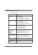
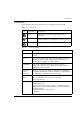
Introduction Conventions The following Tables list conventions that are used throughout this guide. Table P.2 Icon Notice Icons Notice Type Description Note Information that describes important features or instructions Caution Information that alerts you to potential loss of data or potential damage to an application, system, or device Warning Information that alerts you to potential personal injury Table P.
Introduction IV Avaya M770 M-ACCF/SF ATM Access Modules User’s Guide
Contents Introduction ......................................................................................................... I ATM Terminology ...................................................................................I Finding Information in This Guide .......................................................... II Conventions ........................................................................................... III Contents.....................................................................
Contents Network Layer Concepts — ATM & ATM Adaptation ........................... 15 The Layered Network Architecture ...................................................15 ATM Adaptation Layer (AAL) ...........................................................16 Asynchronous Transfer Mode (ATM) Layer ....................................16 ATM Basics .................................................................................16 ATM is Service Transparent .................................................
Contents Setting up the M-ACC Module .............................................................. 45 Changing the Default IP Address of the M-ACC Module Using the CLI ........................................................................................ 45 To connect to the M-SPX/S Console port .............................. 45 Module Setup Main Menu .................................................................. 46 ATM IP Configuration ...............................................................
Contents System Logger Submenu [1,5] .................................................63 Display FLASH Log Messages Submenu [1,5,1] ...................63 Display Memory Log Messages Submenu [1,5,2] .................64 System Software Download Submenu [1,6] ..........................65 Configuring an ATM Port [2] ..............................................................65 ATM access module Configuration ........................................65 Port Submenu [2,1] ......................................
Contents How to Contact Us ....................................................................................................................... 95 In the United States .............................................................................. 95 In the EMEA (Europe, Middle East and Africa) Region ................. 95 In the AP (Asia Pacific) Region ........................................................... 97 In the CALA (Caribbean and Latin America) Region .....................
Contents vi Avaya M770 M-ACCF/SF ATM Access Modules User’s Guide
List of Figures Figure 1.1 Figure 1.2 Figure 1.3 Figure 1.4 Figure 1.5 Figure 1.6 Figure 1.7 Figure 1.8 Figure 1.9 Figure 1.10 Figure 1.11 Figure 1.12 Figure 1.13 Figure 1.14 Figure 1.15 Figure 1.16 Figure 1.17 Figure 2.1 Figure 2.2 Figure 2.3 Figure 3.1 Figure 3.2 Figure 4.1 Figure 4.2 Figure 4.3 Figure 4.4 Figure 4.5 Figure 4.6 Figure 4.7 Figure 4.8 Figure 4.9 Figure 4.10 Figure 4.11 Figure 4.12 Figure 4.13 Figure 4.14 Figure 4.15 Figure 4.16 Basic LAN Emulation Client Connections .......................
List of Figures Figure 4.17 Figure 4.18 Figure 4.19 Figure 4.20 Figure 4.21 Figure 4.22 Figure 4.23 Figure 5.1 viii SNMP Submenu..........................................................................69 updSysAtt Submenu [3,2,6].......................................................71 Community Submenu [3,2,7] ....................................................71 Virtual net Submenu ..................................................................72 ATM Submenu........................................
List of Tables Table P.1 Table P.2 Table P.3 Table 1.1 Table 1.2 Table 3.1 Table 3.2 Table 3.3 Table 4.1 Table 4.2 Table 4.3 Table 4.4 Table 4.5 Table 4.6 Table 4.7 Table 4.8 Table 4.9 Table A.1 Table A.2 Table A.3 Table A.4 Table A.5 Table B.1 Finding Information.................................................................... II Notice Icons................................................................................. III Text Conventions ............................................................
List of Tables x Avaya M770 M-ACCF/SF ATM Access Modules User’s Guide
Chapter 1 Overview ATM Access Modules There are two M-ACC OC-12 ATM Access modules for the Avaya M770 Multifunction switch: • M-ACCF: 500m, Multimode fiber, can also be OC-3 reduced range • M-ACCSF: 15 km, Single-mode fiber, can also be OC-3 The M-ACC ATM Access modules need the following S/W Versions: • M-ACCF/SF ATM Entity S/W Version 1.8 • M-ACCF/SF X-Switch Module S/W Ver. 4.0.7 • M-SPX/M-SPS Embedded S/W 3.2.1 and higher.
Chapter 1 Overview networks. LANE allows users to interoperate with ATM or traditional LAN based servers over ATM for higher performance and functionality. ATM Access Module Features The following list summarizes the ATM access module features. These features are described in more detail in this guide. • Conforms to ATM Forum Standards • OC-12c 622Mbps Interface — SONET (STS 3c/STS 12c) compliant (SDH STM-1/STM-4) — Multimode fiber, SC/SM connectors — Single-mode fiber. • LAN Emulation (LANE) version 1.
Chapter 1 Overview Network Layer Concepts — LAN Emulation The following Sections describe the LAN emulation and ATM adaptation concepts behind the network layer architecture of a typical ATM network. Chapter 2 describes how to plan your ATM network and provides some examples of where to use the ATM access module within an ATM network.
Chapter 1 Overview LAN Emulation Server (LES) The LES coordinates and controls an Emulated LAN. It provides the central “directory” service of an emulated LAN to which a LEC can turn to look up the ATM address of another LEC. The LES directory contains a table of LAN destinations (LAN destination refers to either a MAC address or a Route Descriptor) together with the ATM addresses of the LECs that represent them.
Chapter 1 Overview Emulated LAN Connections LECs and LESs communicate with each other by means of ATM virtual channel connections (VCCs). Control signals and data transmissions are handled by separate VCCs: Control VCCs and Data VCCs. Figure 1.1 Basic LAN Emulation Client Connections Control VCCs The control VCCs carry control traffic such as LE_ARP requests and responses.
Chapter 1 Overview Table 1.1 Control VCCs (Continued) Initialized by VCC Name From/To Information carried Controldistribute LES==>LEC LES LES distributes control traffic to LECs, including LE_ARP information Duration Membership of LEC in ELAN Data VCCs Data VCCs carry data frames between LECs and between a LEC and the BUS. Unicast data is normally sent from one LEC to another LEC by data-direct VCCs.
Chapter 1 Overview Figure 1.2 illustrates the VCCs active among LAN Emulation Components. Figure 1.2 VCCs in LAN Emulation Components Frame Ordering There are two paths for unicast frames between a sending LAN Emulation Client and a receiving client: one via the BUS and one via a data direct VCC between them. For a given LAN destination, a sending client is expected to use only one path at a time, but the choice of paths may change over time.
Chapter 1 Overview Figure 1.3 shows the various stages of the flush protocol: Figure 1.3 The Flush Protocol. 5. Flus h_Res Switch Data Path from Multicast Send to Data Direct using Flush Protocol 6. Flush_Res 1. Data 2. Data h_Req 4. Flus 7. Data Operation of the LAN Emulation The following functions are performed by the LAN Emulation. The LAN Emulation Clients (LEC) and the LAN Emulation Servers interact by way of a well-defined interface (LUNI).
Chapter 1 Overview The LECS Connect and Configuration phases may be bypassed for certain applications. The Registration phase may also be bypassed if the LEC performs required address registration during the Join phase. The Processes connecting the LEC to the ELAN are shown in Figure 1.4. Figure 1.4 Connection Processes of the LEC to LANE Server Registration The address registration function is the mechanism by which LECs provide address information to the LAN Emulation Server.
Chapter 1 Overview Address Resolution Address resolution is the procedure by which a LEC associates a LAN destination with the ATM address of another LEC or the BUS. Address resolution allows clients to set up data direct VCCs to carry frames (refer to Figure 1.5). Figure 1.5 Address Resolution Connection Management In Switched Virtual Connection (SVC) environments, the LAN Emulation entities (LEC, LES and BUS) set up connections between each other using UNI signaling.
Chapter 1 Figure 1.6 Overview LAN Emulation Components Server (LES) ATM Network BUS Client (LEC) Client (LEC) Router LECS (optional) Note: The router shown in Figure 1.6 is not a LAN Emulation component, but would be required should a device on one Emulated LAN need to communicate with a device on another Emulated LAN. LAN Emulation and Avaya Devices LAN Emulation components are implemented in ATM devices.
Chapter 1 Overview Joining the ELAN Before a LAN Emulation Client (LEC) can transmit any Ethernet frames onto the ATM network it must first join an ELAN. To join the ELAN: 1 The LEC must know the name of the ELAN it is to join. The ELAN name is specified through the management software on the Switch. 2 The LEC must communicate with the LAN Emulation Server (LES) that is serving that ELAN. To communicate with the LES, the LEC must first locate the LES.
Chapter 1 Figure 1.7 Overview LAN Emulation Clients and Ethernet Hosts Hosts with MAC Addresses Avaya M770 Multifunction Switch ATM Port with 16 LAN Emulation Clients (LECs) each with an ATM Address ATM Access Module These clients represent (act as a proxy for) devices connected to the Ethernet ports.
Chapter 1 Overview LAN Emulation Address Resolution Protocol (LE_ARP) An LE_ARP request is sent to the LES to locate the destination MAC address. The LES in turn sends the LE_ARP request to all of the LECs in the Emulated LAN. LECs represent (act as a proxy for) MAC address devices connected to the Ethernet ports. When a LEC receives an LE_ARP request it checks whether the MAC address is on its Switch. It does this by checking the entries in the Switch database.
Chapter 1 Overview Network Layer Concepts — ATM & ATM Adaptation This Section describes the following concepts behind the network layer architecture of a typical ATM network: • The Layered Network Architecture • ATM Adaptation Layer (AAL) • Asynchronous Transfer Mode (ATM) Layer • Physical Layer The Layered Network Architecture Asynchronous Transfer Mode (ATM) is one part of the layered network architecture. This architecture is shown in Figure 1.8.
Chapter 1 Overview ATM Adaptation Layer (AAL) Ethernet frames can be between 64 and 1514 bytes in length. ATM transmits data in fixed length cells. Each cell contains 48 bytes of user data. The ATM Adaptation Layer (AAL) converts data between the Ethernet and ATM formats. The AAL has a Segmentation and Reassembly (SAR) sub-layer that does the conversion. In the sending device the LEC passes the Ethernet frames to the SAR.
Chapter 1 Overview physical layer technology to share the same higher layer — the ATM layer. ATM uses fixed length packets called cells. The ATM cell is defined as 48 bytes of payload and 5 bytes of header information totaling 53 bytes. The header contains enough information to allow the network to forward each cell to its proper destination. The cell header also provides the network with the ability to implement congestion control and traffic management mechanisms.
Chapter 1 Overview Cells are de-multiplexed at the other end of the connection and forwarded to the correct service destination. Multi-service processing promotes scalability by significantly reducing the number of changes needed to add new service traffic types to your network. ATM is Connection-Oriented ATM is a connection-oriented transport service that requires a communication channel to be set up between the ATM source and destination end-systems before ATM cells can pass between them.
Chapter 1 Figure 1.11 Overview Connection Terminology Edge-device Virtual Channel ATM ATM Switch Switch ATM Switch A A B Virtual Channel Edge-device Virtual Channel Virtual Channel Connection (VCC) (Also known as Virtual Circuit or Call) Many virtual channels can exist on the same physical link. Each virtual channel is identified by a pair of numbers: • The Virtual Path Identifier (VPI) and • The Virtual Channel Identifier (VCI).
Chapter 1 Overview Connections that are established dynamically using the Signalling protocol are known as Switched Virtual Circuits (SVCs). Switched Virtual Circuits are described on Page 20. ATM connections can also be established via management, and these type of connections are known as Permanent Virtual Circuits (PVCs). Figure 1.12 Switching Cells Using VPI and VCI Values M770 Multifunction Switch with M-ACC Each cell is switched through the ATM network.
Chapter 1 Overview ATM Interfaces ATM technology is implemented in ATM edge-devices and ATM Switches. ATM provides a User-to-Network Interface (UNI). The User-to-Network Interface (UNI) is used to connect an ATM edge device to an ATM switch that is managed as part of the same network. ATM also provides a Network-to-Network Interface (NNI) that is typically used to interconnect two ATM switches managed as part of the same network. The ATM Interfaces are shown in Figure 1.13. Figure 1.
Chapter 1 Overview Figure 1.14 UNI Management Entities Avaya M770 Multifunction Switch (M-ACCF OC-12 Module) UME in ATM Access Module ATM Switch UME (M770 ATM Switch) ATM Address Registration In order to establish an ATM connection, both the user and the network must know the ATM addresses used at that User-to-Network Interface (UNI). An example of an ATM address is shown below. 47.00.79.00.00.00.00.00.00.00.00.00.00.00.A0.3E.00.00.01.
Chapter 1 Overview The ATM cell has 48 bytes of payload (information to be carried) and five bytes of header information, making the cell 53 bytes in length. The cell header contains the information used by the network to forward each cell to its destination. The ATM cell structure is shown in Figure 1.15. Figure 1.
Chapter 1 Overview Physical Layer The physical layer is responsible for transmitting and receiving ATM cells over a physical medium. It is also responsible for checking the integrity of the bits being transferred over a physical media, and for making sure that they are error-free. The ATM access module is compliant with both SONET STS-3c and SDH STM-1 physical layer standards. These standards are similar, and most devices allow you to use either framing standard on each link in the ATM network.
Chapter 1 Overview Note: ELAN-to-VLAN and VLAN-to-ELAN mapping is only one-to-one. Unassociated packets/cells are discarded. Figure 1.
Chapter 1 Overview Figure 1.17 Extending VLANs into the ATM Network.
Chapter 2 Applications Putting Your ATM Network Together This Section takes you through the process of planning your network. Topics include: • Planning Your Network • ATM Configuration Rules • Extending VLANs Through the ATM Network • ATM Connections Within Your Network. Planning Your Network Before installing your ATM devices you should spend some time planning your network structure. This section lists some of the points you should consider.
Chapter 2 Applications Note: For the ATM access module these requirements are specified in Appendix A, Specifications. For other devices, refer to the user guides that accompany those devices. • Does your network conform to the ATM configuration rules? Ensure that your network meets the configuration rules described below. ATM Configuration Rules There are several things that you should consider before configuring your network: • Your cables and equipment must meet all of the technical specifications.
Chapter 2 Applications Extending VLANs Through the ATM Network When setting up VLANs and extending them into the ATM network you should consider the following (see Figure 1.17): • What logical network domains, VLANs, do you wish to set up? Traffic from one Emulated LAN (ELAN) will not be seen on another ELAN (unless a router is used), as they are logically separate domains. For this reason you should consider: — What ELANs you require. — How the VLANs will map to the ELANs.
Chapter 2 Applications Note: Configuring the LECS and LES is outside of the scope of this user guide. Consult the user guide that accompanies the device implementing the LECS or LES. Alternatively, if your LEC will not be using a LECS and is being configured manually, ensure that: — The LES address that the LEC is using has been correctly entered via the local management screens. — The LES is active.
Chapter 2 Applications Network Configuration Examples This Section provides examples of possible network configurations using the M-ACC module. If you are unfamiliar with ATM, see the Section, entitled Planning Your Network. ATM Backbone in the Building An example of an ATM backbone within a single building, is shown in Figure 2.1. In this case, the Ethernet Switch on each floor is provided with a high speed (622 Mbps) full duplex link to the backbone.
Chapter 2 Applications Figure 2.
Chapter 2 Applications Avaya M770 Multitechnology Functionality This section gives an example of ATM within a WAN environment connecting various sites. Using the M-ACC module we can leverage the Multifunctionality of the Avaya M770 and connect Fast Ethernet PC desktops to the same single chassis. In Figure 2.2, ATM was chosen to efficiently transfer both voice and data on a single trunk.
Chapter 2 Applications Routing in the X-Switch Domain The principle behind the Avaya routing evolution is to move routing from the backbone to the edges. This controls the traffic from the moment it enters the LAN and not just after it reaches the backbone. Figure 2.3 shows how an M-MLS routing module in one of the 2 Avaya M770 Multifunction switches can provide routing for all users on either side of the ATM network. The Avaya M770 is connected to the ATM cloud via the M-ACC ATM Access Modules.
Chapter 3 Installation Installing the M-ACC Module Safety Information Warning: Before installing or removing any components of a device, or carrying out any maintenance work, you must read the safety information provided in Appendix A, Important Safety Information. Disconnect the device from the main power supply. Warning: Installation and removal of the ATM access module must be carried out by qualified personnel only.
Chapter 3 Installation Single-mode Module Laser Classification CLASS 1 LASER PRODUCT Note: Class 1 lasers are inherently safe under reasonably foreseeable conditions of operation. Caution: The use of optical instruments with this product will increase eye hazard. Multi-Mode Module LED Warning The following warnings apply to the M-ACCF ATM access module equipped with multi-mode fiber. Class 1 LED Product Warning: Class 1 LED Product.
Chapter 3 Installation Domain Usage Considerations The M-ACC is a DomainX module of the Avaya M770. The maximum number of DomainX modules you can insert in the hub is determined by domain usage considerations, as follows (M-SPX refers to either the M-SPV, M-SPX or M-SPS in the following examples): The Avaya M770 allows a maximum of 100 Domain Resource Units (DRUs) for DomainXL (Left DomainX - slots 1-7) and the M-SPX, and 100 DRUs for DomainXR (Right DomainX - slots 8-14) and the M-SPX.
Chapter 3 Installation Note: A redundant M-SPX does not count in the DRU calculations. However you must include the active M-SPX twice, once for DomainXL and once for DomainXR. DRU Budget Information Window You can check the DRU budget information for your Avaya M770 hub via the CajunView ‘ Network Management System (NMS). The following window shows an example of a chassis with an M-SPV, M32-100T, M12-100F and an M12-100T module.
Chapter 3 Installation Installing the Module Caution: The ATM access modules contain components sensitive to electrostatic discharge. Do not touch the circuit board unless instructed to do so. Note: The Avaya M770 chassis must not be operated with the module slot open; the slot should be covered with the supplied blanking plate if necessary. Note: M-ACC modules are hot swapable. The M-ACC occupies one slot in the Avaya M770 chassis and can be inserted into any available slot.
Chapter 3 Installation Figure 3.1 Inserting the Module into the Hub Upper Guide Rails DomainX Module Av Muaya ltif M7 u Sw nct 70 itc ion h Plastic Handle Module Name and LEDs Panel Plastic Handle Lower Guide Rails Motherboard Connector Power-on Check When you plug in the M-ACC, all the LEDs light steady for a few seconds. Wait until the Port LEDs blink before commencing work. Connecting a Cable to the ATM Port 1 Ensure that the cable you wish to connect to the port meets the correct specification.
Chapter 3 Installation Power On Self Test When you power up the Avaya M770 switch with an M-ACC module inserted, both pass a self test. This check takes between 10 and 20 seconds to complete, and includes: — Checksum tests of boot and system areas of Flash memory — System memory tests — MAC address verification test — System timer test — CAM (Contents Addressable Memory) tests — Console Port tests — Internal packet forwarding tests — ASIC tests — Module interface tests — Module packet forwarding tests.
Chapter 3 Installation Post-Installation Checks Figure 3.2 shows M-ACC front panel with its LEDs, switches and connectors (described in Table 3.2). When you insert an M-ACC ATM Access module into the Avaya M770 chassis or after a reset, there is a Startup sequence which takes about 30 seconds before the ATM lights ON. Table 3.
Chapter 3 Installation Configuring the M-ACC Module The M-ACC module can be configured using the text-based Command Line Interface (CLI) utility and the Terminal Interface. The LEC Information Table, ATM Access module and ATM port information can be viewed using CajunView™. For instructions on the text-based utility, see Chapter 4. For information about the graphical user interfaces, see Chapter 5. For instructions on the use of the graphical user interfaces, refer to the Manager User’s Guide on the CD.
Chapter 3 Installation The RJ-45 port on the front of the module is labeled “Console”, and may be used to configure the switch using the built-in Command Line Interface (CLI, Terminal Emulation). In the future, this connector will also be used for out-of-band SNMP management, via a modem. The port settings are as follows: • Baud Rate - 9600 bps • Character Size - 8 • Parity - None • Stop Bit - 1 • Flow Control - None • We recommend using a VT-100 terminal to enable access to all CLI features.
Chapter 3 Installation Setting up the M-ACC Module Before you can set up the M-ACC module you must power on and set up the Avaya M770 switch as described in the Avaya M770 User Guide. The following steps describe how to configure the M-ACC module using the Avaya M770 CLI. Changing the Default IP Address of the M-ACC Module Using the CLI To begin using the ATM access module you must first assign an IP address and ATM capabilities to the module via the CLI of the X-switch CPU.
Chapter 3 Installation Module Setup Main Menu Setup Main Menu M-ACCF 0. S/W Version: 4.0.7 Slot #: 5 Refresh the screen Return to Previous Menu ----------------------------------1. Reset the Module 2. Software Download … 3. Set Primary Version … 4. Set Factory Defaults 5. Create Report 6. Clear Mac Address Table 7. Configuration Copy 8. ATM IP Configuration … >>>Enter your choice: The module Setup Main Menu lists the various categories of M-ACC configurable parameters.
Chapter 3 Installation Note: The default Gateway must be on the same Subnet as the IP address assigned in Step 2 (above) for the ATM access module. 4 There is no need to perform a reset. Configuration Example: Enter IP Address (149.49.54.249): 149.49.44.80 Enter Netmask (255.255.255.0): 255.255.255.0 Enter Default Gateway (149.49.54.1): 149.49.44.120 Note: If there are any errors, the new configuration settings are not saved.
Chapter 3 Installation Note: M-MLS Bridging While the M-ACC and M-MLS bridge may be installed in the same Avaya M770 chassis, Layer 2 Bridged Packets cannot pass the ATM cloud.
Chapter 4 X-Switch CLI & ATM Terminal Interface Introduction There are several interfaces for configuring the ATM access module: • X-Switch Command Line Interface (CLI) Basic module configuration via the Console port of the M-SPX/S Avaya M770 Supervisor Module or Telnet to the Switch IP address. • M-ACC ATM Access Module Terminal Menu Interface ATM Edge Device parameters setup such as LECS, LES and BUS via the Console port of the M-ACC or to the M-ACC module IP address.
Chapter 4 X-Switch CLI & ATM Terminal Interface Conventions Used The following conventions are used in this document to convey instructions and information: • Mandatory keywords are in boldface • Variables that you supply are in pointed brackets <> • Optional keywords are in square brackets [ ] • Alternative but mandatory keywords are grouped in braces { } and separated by a vertical bar | • If you enter an alphanumeric string of two words or more enclose the string in inverted commas.
Chapter 4 X-Switch CLI & ATM Terminal Interface X-Switch Command Line Interface (CLI) This is the Command Line Interface (CLI) used with the ATM module. Most parameters are set using the Terminal Interace (see ATM Access Module Terminal Interface for Configuring ATM Parameters58). To begin using the ATM access module you must first assign an IP address and ATM capabilities to the module via the CLI (see ATM IP Configuration46).
Chapter 4 X-Switch CLI & ATM Terminal Interface 4 The Switch Main Menu displays: Switch Main Menu ---------------------------------Select an Agent to configure: Refresh the screen 0. Return to Previous Menu 1. Direct Access to specific module 2. M-SPX in slot: 15 manages modules: 3,4,5,7,9,10,11 >>>Enter your choice When you choose Option 1 and enter the M-ACC slot number, you reach the M-ACC’s Setup Main Menu. Module Setup Main Menu Setup Main Menu M-ACCF 0. S/W Version: 4.2.
Chapter 4 X-Switch CLI & ATM Terminal Interface Note: The “Reset the Module” option does not reset the entire hub; it resets the selected module only. Software Download to the X-Switch CPU You can download software to the X-Switch entity (CPU) of the M-ACC module using the TFTP/IP protocol. To enable the process, make sure there’s a reachable TFTP server in the network. To download a software update to the M32-100T, use the Software Download option (option 2 from the Setup Main Menu).
Chapter 4 X-Switch CLI & ATM Terminal Interface oldest version. If you wish the M-ACC to load and run the new software version, select option Set Primary Version (option 4) from the Setup Main Menu. Specify the new software version as the Primary version (refer to section Set Primary Version). 4 Note: The M-ACC does not perform a reset after the software download process. To reboot, select the Reset the M-ACC option from the Setup Main Menu.
Chapter 4 X-Switch CLI & ATM Terminal Interface Set Primary Version The M-ACC stores two software versions. The version which is currently running is called the Primary version. A pointer (asterisk - *) shows which version is currently the primary one. To set a different primary version, select option 4 from the Setup Main Menu. A menu similar to the following displays: Primary Version Screen M-ACCF S/W Version: 4.2.2 Slot #: 5 Refresh the screen 0. Return to Previous Menu 1.
Chapter 4 X-Switch CLI & ATM Terminal Interface Clear Mac Address Table Option 6 from the Main Menu 'Clear Mac Address Table', allows you to clear the MAC address table of the entire Avaya M770 domain from a single point. This is performed as follows (from the Main Menu): >>>Enter your choice: 6 Proceed with clearing the MAC address table ? [Y/N] y ...MAC address table was cleared. Reset is required to make the change effective. Reset now ? [Y/N] y Resetting. Please Wait ...
Chapter 4 X-Switch CLI & ATM Terminal Interface Assigning the M-ACC module IP address, Gateway and Netmask: 1 Select Option 1 “Set IP Configuration” 2 Check that the LED labelled OPR, on the ATM access module front panel is ON. 3 Type the IP address, net mask and default gateway of the ATM access module when prompted. Note: The default Gateway must be on the same Subnet as the IP address assigned in step 2 (above) for the ATM access module. 4 There is no need to perform a reset.
Chapter 4 X-Switch CLI & ATM Terminal Interface ATM Access Module Terminal Interface for Configuring ATM Parameters To use this terminal interface you must connect the terminal to the ATM Access module Console port or start a Telnet session to the ATM module IP address. You can establish a connection only after the ATM module has an IP address and connectivity to the server. Use the M-ACC CLI to perform these two prelimiary tasks (see the Section, X-Switch Command Line Interface (CLI)51).
Chapter 4 X-Switch CLI & ATM Terminal Interface For access rights to Switch screens, see the user guide that accompanies your Switch. When you have logged on, the Main Menu screen is displayed. Logging Off When you have finished using the facility, select the option quit from the bottom of the Main Menu. If you accessed the facility using a Telnet session or modem, the connection will be closed automatically. To disconnect a session, the disconnect command may be used.
Chapter 4 X-Switch CLI & ATM Terminal Interface Figure 4.
Chapter 4 X-Switch CLI & ATM Terminal Interface Main Menu Options The Main menu, see Figure 4.2, provides the following options: Figure 4.2 Main Menu Main Menu ========= [1] [2] [3] [4] [5] system atm management vn quit - Administer system level functions -> Administer ATM resources -> Administer IP and SNMP -> Administer virtual networks -> Logout of the administration console Configuring System Parameters [1] The System menu, see Figure 4.3, allows you to administer system level functions.
Chapter 4 X-Switch CLI & ATM Terminal Interface Display Submenu [1,1] This option provides the general software version parameters. See Figure 4.4. Figure 4.4 Display Submenu Time since reset: Operational version: Creation date: Hardware version: Monitor version: MAC address: Serial number: Power up diag results: 002 Days 01 Hrs 17 Mins 25 Secs 1.8 Apr 11 2000 17:57:19 503A0130-1C 6 2.
Chapter 4 X-Switch CLI & ATM Terminal Interface System Logger Submenu [1,5] The Logger submenu is shown in Figure 4.6. Figure 4.6 Logger Submenu System Logger Menu ================== [1] dispFlash [2] dispMem - Display FLASH log messages -> - Display memory log messages -> Display FLASH Log Messages Submenu [1,5,1] Figure 4.7 shows the Display FLASH Log Messages submenu. Figure 4.
Chapter 4 X-Switch CLI & ATM Terminal Interface Display Memory Log Messages Submenu [1,5,2] Figure 4.8 shows the Display Memory Log Messages submenu. Figure 4.8 Display Memory Log Messages Submenu Display Memory Log Messages Menu ================================ [1] [2] [3] [4] [5] [6] num start next prev all clear Table 4.
Chapter 4 X-Switch CLI & ATM Terminal Interface System Software Download Submenu [1,6] This option (see Figure 4.9) is used for the TFTP procedure for downloading new software versions. See Upgrading Software on 75 for more details. Figure 4.
Chapter 4 X-Switch CLI & ATM Terminal Interface Note: Ensure that the ATM access module and the ATM Switch to which it is connected are set up to use the same signalling and SONET/SDH standards. The two devices should also use the same ILMI VCC, signaling VCC, and UNI version. If the devices do not use the same standards, they cannot communicate with each other. Port Submenu [2,1] The Port submenu enables port attributes display, statistics, and settings. See Figure 4.11. Figure 4.
Chapter 4 Figure 4.12 X-Switch CLI & ATM Terminal Interface Display Results Admin Status Oper Status UNI version ILMI VCC Signaling VCC Signaling Time Resolution Speed Type Fiber mode Fast link recovery state ILMI synchronization mode : : : : : : : : : : : Up Up 3.
Chapter 4 X-Switch CLI & ATM Terminal Interface Figure 4.14 VCC Submenu ATM VCC Menu ============ [1] [2] [3] [4] display statistics bits aging - Display VCC information Display per VCC statistics Display significant VPI/VCI bits Administer VCC aging -> Table 4.5 explains the operational meanings of the submenu items. Table 4.
Chapter 4 X-Switch CLI & ATM Terminal Interface Administering IP and SNMP Management [3] This menu option, see Figure 4.16, allows you to configure the ATM access module IP and SNMP information for use with the SNMP Network Management Station (NMS). Figure 4.16 Management Submenu Management Menu =============== [1] ip [2] snmp - Administer IP -> - Administer SNMP -> IP Submenu [3,1] This menu displays IP configuration.
Chapter 4 X-Switch CLI & ATM Terminal Interface Table 4.6 describes the operational meanings of the SNMP Configuration options. Table 4.
Chapter 4 Figure 4.18 X-Switch CLI & ATM Terminal Interface updSysAtt Submenu [3,2,6] Attribute Menu ============== [1] contact [2] name [3] location Figure 4.
Chapter 4 X-Switch CLI & ATM Terminal Interface Extending VLANs into the ATM Network [4] This section describes how to extend VLANs into the ATM network. The ATM port can be in one or more VLANs. Each VLAN is associated with a LEC on the ATM access module, and each LEC is mapped to an ATM ELAN. Note: You can make a maximum of 16 ELAN-to-VLAN associations per M-ACC ATM Access module (in the range VLAN 1 to 254 only).
Chapter 4 X-Switch CLI & ATM Terminal Interface Table 4.7 explains the operational meanings of the submenu items. Table 4.7 Item Configure Submenu Items and their Operational Meanings Operational Meaning [1] display Displays the LEC status for each VN. [2] info Displays VLAN/ ELAN information. Entry/ Display Entry/Display/Change Meaning VN 17 is for internal use only and is always UP. VLAN/ ELAN ID. Used to display internal VLAN/ELAN identifier (1-16). Configured ELAN name.
Chapter 4 X-Switch CLI & ATM Terminal Interface Table 4.7 Operational Meaning Entry/ Display [4] delete Deletes an ELAN/ VLAN association. VN Number Deletes a new VLAN/ELAN Association. [5] lec Allows you to control LEC status. VN Number, Enable, Disable Restart. You can enable, disable or restart a VN LEC. [6] name Allows you to change an ELAN name for a selected VN.
Chapter 4 X-Switch CLI & ATM Terminal Interface Setting up an ATM VLAN/ELAN 1 2 3 4 Go to the VN [4] submenu. Select [3] Create. Enter the VN number (2 to 16), the 802.1Q tag as configured in the ATM access module VLAN settings (2 to 254, not 17 - for internal use) and the ELAN name as configured in the LECS. Observe creation and enabling of a new VLAN/ELAN using the Display [1] option in the VN menu. Upgrading Software This section describes how to upgrade the ATM access module software.
Chapter 4 X-Switch CLI & ATM Terminal Interface Caution: Before you reset the ATM access module, please check that the download is complete (download_success should be displayed in step 8 above). Any reset before the download is complete may make the module unusable. 9 After the software upgrade procedure is completed, you must reset the ATM access module in order to validate the new software version.
Chapter 4 X-Switch CLI & ATM Terminal Interface Select the [2] vcc option to generate the Atm Port Statistics display. Then select the [2] statistics option. An example of the ATM Port Statistics screen is shown in Figure 4.22. Figure 4.22 ATM Port Statistics Screen In Cells: 23 In Frames: 11 In Errored Frames: 0 Out Cells: 14 Out Frames: 5 Out Errored Frames: 0 Note: The figures shown for each statistic on this screen include ATM management traffic and normal Ethernet traffic.
Chapter 4 X-Switch CLI & ATM Terminal Interface VCC Statistics The VCC Statistics screen provides an overview of traffic flow in each VCC. To view the VCC statistics: 1 Select the [2] atm option in the Main Menu. The ATM submenu (see Figure 4.21) appears. 2 Select the [2] vcc option in the ATM submenu and observe the ATM/VCC submenu (see Table 4.5) appear. 3 Select the [2] Statistics option. 4 Enter the VPI /VCI of the VCC traffic you want to monitor. 5 The VCC Statistics display (see Figure 4.
Chapter 5 Network Management and Monitoring Introduction The M-ACC ATM Access module can be managed using several NMS tools in addition to the Command Line Interface (CLI) and Terminal Interface described in Chapter 4: • CajunView M770 Device Manager (version 4.0): The M770 Device Manager enables you to see the LEC information table for the ATM access module, information about the ATM access module and the ATM port. • Cajun LANEMaster (version 2.
Chapter 5 Network Management and Monitoring CajunView M770 Device Manager The M770 Device Manager provides full management capabilities for the Avaya M770. This includes the ability to view the following aspects of device management: • Device Manager - Provides a view of the configuration of the device including VLAN configuration, configured LAGs, port mirroring, traps, etc. • Routing Manager - Provides a view of the third layer routing and forwarding functions of the device.
Chapter 5 Network Management and Monitoring LANEMaster Overview Cajun LANEMaster provides a simple method of managing LAN Emulation on an ATM network using Avaya M770 ATM Devices (see Figure 5.1). Cajun LANEMaster provides an overall view of both the physical and logical structure of the network, and the configuration parameters of the LANE components. Cajun LANEMaster also provides an easy way to associate ELANs to VLANs.
Chapter 5 Network Management and Monitoring Cajun LANEMaster Views This section provides a detailed description of the ways you can view the network. It includes the following sections: • Overview - An overview of the different views of the network. • Using the Tree View - A detailed description of the Tree View and its hierarchy.
Chapter 5 Figure 5.
Chapter 5 84 Network Management and Monitoring Avaya M770 M-ACCF/SF ATM Access Modules User’s Guide
AppendixA Specifications M-ACC ATM Access Module Technical Specifications This appendix describes the following topics: • Environmental, Safety, and EMC Specifications • ATM Cable Specification Environmental, Safety, and EMC Specifications The environmental, safety, and EMC specifications for the ATM Access module are shown in Table A.1 and Table A.2. Table A.
Appendix A Specifications Optical Standard Supported ATM Forum • • • LANE 1.0 UNI 3.0, 3.1 ILMI 3.0, 3.1 ITU-T • OC-12c/3c: ITU-T G.957 and G.958 SDH Standard Supported ITU-T • OC-12c/3c: I.432 , G.707-9 Avaya supports 62.5/125mm Multi-Mode Fiber (MMF-PMD). The maximum interstation distance (including device-to-network connectors) should not exceed 2 kilometers (1.25 miles). Table A.3 shows the cable specifications for standard multi-mode cabling: Table A.
Appendix A Table A.4 Specifications Standard Multi-mode Cable Specifications (continued) SONET Type Attenuation (db) Mean Launched Power (dBm) Minimum Receiver Sensitivity (dBm) OC-12c MMF 6.0 -20 to -14 -26 (LED Based) 2.0 -24 to -14 -26 OC-3c MMF 6.0 -20 to -14 -26 (OC-12c Transceiver Based) 2.0 -24 to -14 -26 Table A.5 shows the cable specifications for standard single-mode cable specifications (OC-12c/OC-3c Short Reach). Table A.
Appendix A Specifications Safety Information You must read the following safety information before carrying out any installation or removal of components, or any maintenance procedures. Important Safety Information Warning: Warnings contain directions that you must follow for your personal safety. Follow all instructions carefully. Please read the following safety information thoroughly in conjunction with the safety information supplied with the Switch before installing the ATM Access module.
Appendix B Troubleshooting Use the table below to troubleshoot common problems. If you still experience problems, please contact Avaya’s Technical Support. Table B.1 Troubleshooting Tips Problem Probable Cause Solution 1)The ATM Access module IP does not answer Ping (general) 1)Not inserted correctly in M770 switch. 2)No power 3)Incorrect IP parameters 1)Check that it is inserted all the way into the switch and that the screws are tightened.
Appendix B 90 Troubleshooting Avaya M770 M-ACCF/SF ATM Access Modules User’s Guide
Index Numerics 802.
Index B bandwidth calculation 86 bridged-LAN environments connecting 3 broadcast packets 24 BUS 24 C cable connecting 40 cable specification 85 optical standard supported 86 SDH standard supported 86 cables connecting to the ATM Module 40 Cell Loss Priority (CLP) 23 cell structure 23 changing ATM Port physical attributes 67 community strings 70 ELAN name 74 community strings administering 70 changing 70 configuration rules for ATM 28 configuring ATM Port 65 connections connecting cables 40 control 29 data
Index I Interim Local Management Interface (ILMI) 21 address resolution 22 L LAN Emulation (LANE) address resolution 10 benefits 1 connection management 10 frame ordering 7 LE_ARP 14 registration 9 within Lucent devices 11 LAN Emulation Client (LEC) MAC address proxy 13, 14 LAN Emulation Configuration Server (LECS) ATM address 12 LAN Emulation Server, see LES LAN Emulation Service 10 LAN Emulation(LANE) components 10 LEC in ATM edge device 3 LUNI 8 LEC status 73 LEC to ELAN connecting 8 LEC to LES connecti
Index overview 76 sampling period 76 Switched Virtual Circuit (SVC) when to use 30 switching technology 16 T technical specifications cabling 85 environment 85 technology, switching 16 TFTP procedure for downloading software TFTP server 75 20, 30 65 U unicast frames 14 flush protocol 7 paths 7 unicast packets 24 updating authentication trap generation 70 NMS IP address 70 user guide finding information II users default 58 User-to-Network Interface (UNI) 21 94 V VCC statistics 78 submenu 67 viewing ATM
How to Contact Us To contact Avaya’s technical support, please call: In the United States Dial 1-800-237-0016, press 0, then press 73300.
Country Local Dial-In Number Country Local Dial-In Number Lebanon +31 70 414 8053 Slovakia +31 70 414 8066 Lithuania +370 2 756 800 Slovania +31 70 414 8040 Luxemburg +352 29 6969 5624 South Africa +0800 995 059 Macedonia +31 70 414 8041 Spain +34 91 375 3023 Malta +31 70 414 8022 Sweden +46 851 992 080 Mauritius +31 70 414 8054 Switzerland +41 22 827 8741 Morocco +31 70 414 8055 Tanzania +31 70 414 8060 Netherlands +31 70 414 8023 Tunisia +31 70 414 8069 Nigeria +31 70
In the AP (Asia Pacific) Region Country Local Dial-In Number Country Local Dial-In Number Australia +1800 255 233 Malaysia +1800 880 227 Hong Kong +2506 5451 New Zealand +00 800 9828 9828 Indonesia +800 1 255 227 Philippines +1800 1888 7798 Japan +0 120 766 227 Singapore +1800 872 8717 Korea +0 80 766 2580 Taiwan +0 80 025 227 Email: sgcoe@avaya.com In the CALA (Caribbean and Latin America) Region Email: caladatasupp@avaya.
avaya.com All trademarks, registered trademarks, service names, product and/or brand names are the sole property of their respective owners. Copyright © 2001 Avaya Inc. All rights reserved.