
Configuration Guide


Chapter 1 Overview 23
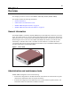
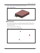
R2MFC Media Bay Module Installation and Configuration Guide
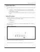
System Status LEDs
The R2MFC MBM has three visual status monitor indicators on the left side of the faceplate. They
are:
• Power LED — This green LED indicates the status of power to the R2MFC MBM.
• In Service LED — This green LED indicates the status of the E1 signal coming to the
R2MFC MBM from the BCM.
• Diag LED — This red LED indicates if the R2MFC MBM is in a diagnostic or loopback
mode.
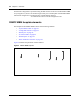
Config DIP switches
The R2MFC MBM has six config DIP switches on its faceplate. These DIP switches are used to
set the following configurations for the R2MFC MBM:
• country
• problem diagnosis
• second dial tone
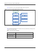
DIP switches must be set before power is connected to the R2MFC MBM. Figure 3 shows the
Config DIP switches.
Figure 3 Config DIP Switches
For DIP switch values and configuration information, see “Configuring the MFCR2 (external)
link” on page 45.
These DIP switches are also used for problem diagnostics. For specific settings and uses, see
“Diagnostic tools” on page 57.
ON
123456
123456
O
N
country
second
dial
tone
diagnostic
s
configuration
country