Ambient Level Controller Installation and Use Manual Issue 1, October 1999 © 1999 Bogen Communications, Inc. All rights reserved.
© 1999 Bogen Communications, Inc. All Rights Reserved. Printed in U.S.A. Notice Every effort was made to ensure that the information in this guide was complete and accurate at the time of printing. However, information is subject to change.
Contents Page 1. Overview ....................................................................................................................................1-1 Features ............................................................................................................................1-2 Specifications ....................................................................................................................1-4 Before You Start ............................................................
This page intentionally left blank
Overview 1 Contents Features 1-2 Specifications 1-4 Before You Start 1-5 Overview 1-1
Features ■ Allows automatic, manual or remote control of sound system levels. ■ It has an SPL meter with over 50 dB range built in. ■ The microphone can be placed up to 5000 feet from unit. ■ Simplicity in set up and operation. ■ Single rack space - 1 RU. ■ Balanced 600 ohm inputs and outputs. ■ Line input activated by a contact closure. ■ Loop start TELCO input with priority over line input. ■ Clock inputs or remote control connections.
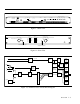
Power Input 24 Volts AC Line In Telco In Loop Start C1 G + - Clock Inputs or Remote Control -24dB -24dB -18dB -12dB -6dB Relay Outputs Shield Model FM-15 + - Mic Only Mic Only Line Out Output Level NO 1 C NC NO 1 C NC NO 1 C NC NO 1 C NC C1 C NO C 1 NO C 1 NO C 1 NO C 1 NO C 1 Figure 1-1.
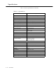
Specifications Table 1-1 lists the specifications for the ALC. Table 1-1. Specifications Parameter Working Limits Power Source 24 Volts AC UL listed power supply Maximum Power Consumption 60 Watts Frequency Response 250 Hz to 15KHz +/- 2dB Signal To Noise [dB ref.] Better than -60 dB Maximum Output Level 0 dB,-12 dB with jumper Output Relay Trigger Points 0 dB and -6 dB gain reduction Output Relay Contact Rating 1 amp No.
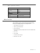
Table 1-1. Specifications (Continued) PHYSICAL Depth 8-3/4 inches Width With Rack Ears 17 inches 19 inches Height 1-3/4 inches Weight 8 pounds ENVIRONMENTAL Temperature Operating +32° to +104°F (0 to 40°C) Humidity 0 to 85% Noncondensing Before You Start Before installing your system, read and understand the safety instructions. Be sure you have all the necessary parts, tools, and test equipment, listed below. Check the shipping container for the following contents: 1.
This page intentionally left blank 1-6 Overview
Operation 2 Contents Front Panel Setup 2-2 Manual Use of the FM-15 Ambient Level Controller 2-3 FM-14 Log Current Microphone Hookup 2-4 Operation 2-1
Front Panel Setup Set up the FM-15 ALC as follows: 1. Set the MANUAL LEVEL CONTROL to automatic (Blue Knob) (see Figure 2-1). This allows the FM-15 ALC to calibrate itself.The automatic position will allow the FM-15 ALC to constantly change the paging level to compensate for the changes in noise level in the area being monitored. 2. Check the SPL meter (the Green LED) (see Figure 2-1) for maximum noise level. This is your high noise level reading. 3.
Manual Use of the FM-15 Ambient Level Controller The FM-15 ALC may be used without the FM-14 Log Current Microphone. In this mode, the FM-15 ALC becomes a leveler or limiter for manual control of the sound system. The SPL meter will not function but all other functions will work in the normal manner. The Manual Level Control on the front panel will set the level of the sound system (see Figure 2-1). The Output Level Control (see Figure 2-2) is preset at the factory for a 0 dB maximum output level.
FM-14 Log Current Microphone Hookup The wire for the FM-14 Log Current Microphone does not have to be shielded. Use an RJ-11 connector at the microphone. When connecting to the FM-15 ALC use an RJ-11 connector or wire directly to the terminal strip marked MIC ONLY (see Figure 2-3). OR Output Level Line Out + - Mic Only NOTE: These terminals are redundant MIC input connections, useful when a Modular RJ-11 Plug and cable is not suitable. Mic Only NO 1 C C1 C Figure 2-3.
Installation 3 Contents Power Supply Hookup 3-2 Mounting Detail 3-3 Ambient Level Controller Connection With A LUUPAM Universal Paging Access Module 3-5 Ambient Level Controller Connection With LUPCM Paging System 3-6 Installation 3-1
Power Supply Hookup Power Input 24 Volts AC Telco In Loop Start Line In C1 G + - BLACK WHITE RED GREEN Model FM-15 Shield Install the FM-15 ALC with the system to be controlled. Then install the FM-14 Log Current Microphone in the area to be controlled. Connect the power supply provided as marked on the PC board (BLACK-WHITE-REDGREEN, from left to right) (see Figure 3-1). POWER SUPPLY 24VAC 1.6 60 HZ DO NOT DEFEAT THE SAFETY GROUNDING PIN ON THE POWER LUG. Figure 3-1.
Mounting Detail The rack ears mount in any of four directions (see Figure 3-2). This makes rack mounting or wall mounting possible. The power supply can be mounted in any convenient place. FRONT DETAIL 1.
Figure 3-3.
Ambient Level Controller Connection With A LUUPAM Universal Paging Access Module The FM-15 ALC connects between the paging source (PBX, Key System or standard telephone, and the paging amplifier) (see Figure 3-3). NOTE: Loop start only. Do not apply Ring Voltage! Figure 3-3.
Note: The controller must be switching line level only Multiple FM-15 ALCs may be used with a single controller so each zone has its own level correction (see Figure 3-4). Figure 3-4.