Instruction Manual Pass onto user to read and keep for reference 74401 Threaded Insert Power Tool
Avdel UK Limited policy is one of continuous development. Specifications shown in this document may be subject to changes which may be introduced after publication. For the latest information always consult Avdel.
CONTENTS SAFETY General 2 Specific to Type of Tool 3 General 4 Tool Dimensions 4 Air Supply 5 Stroke Adjustment 5 Operating Procedure 6 Connnecting the Foot Pedal 7 Fitting 8 Servicing 8 Components 9 INTENT OF USE PUTTING INTO SERVICE NOSE ASSEMBLIES SERVICING Regular Servicing 10 Service Kit 10 Maintenance 11-13 General Assembly & Parts List 14-20 PRIMING FAULT Priming Oil Details 22 Priming Procedure 22 Fault Diagnosis Table 23 DIAGNOSIS 1
S AFETY This instruction manual must be read with particular attention to the following safety rules, by any person installing, operating, or servicing this tool. DO NOT USE OUTSIDE THE DESIGN INTENT. DO NOT USE EQUIPMENT WITH THIS TOOL/MACHINE OTHER THAN THAT RECOMMENDED AND SUPPLIED BY AVDEL. ANY MODIFICATION UNDERTAKEN BY THE CUSTOMER TO THE TOOL/MACHINE, NOSE ASSEMBLIES, ACCESSORIES OR ANY EQUIPMENT SUPPLIED BY AVDEL OR THEIR REPRESENTATIVES, SHALL BE THE CUSTOMER'S ENTIRE RESPONSIBILITY.
In addition to the general safety rules opposite, the following specific safety points must also be observed: THE OPERATING PRESSURE SHALL NOT EXCEED 7 BAR - 100 LBF/IN 2 . DO NOT OPERATE THE TOOL WITHOUT FULL NOSE EQUIPMENT, OIL PLUG AND OIL BLEED SCREW IN PLACE. WHEN USING THE TOOL, THE WEARING OF SAFETY GLASSES IS REQUIRED BOTH BY THE OPERATOR AND OTHERS IN THE VICINITY TO PROTECT AGAINST FASTENER PROJECTION, SHOULD A FASTENER BE PLACED ‘IN AIR’.
I NTENT OF USE The hydro-pneumatic 74401 tool is designed to place Avdel threaded inserts at high speed making it ideal for batch or flow-line assembly in a wide variety of applications throughout all industries. Use the selection chart page 7 to select a complete tool. It is also possible to order the handle with no hoses, part number 74401-12000, or the cabinet only, part number 07265-03201.
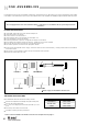
AIR SUPPLY PUTTING INTO SERVICE All tools are operated with compressed air at an optimum pressure of 5.5 bar. We recommend the use of pressure regulators and automatic oiling/filtering systems on the main air supply. These should be fitted within 3 metres of the tool (see diagram below) to ensure maximum tool life and minimum tool maintenance.
OPERATING ■ ■ ■ ■ PROCEDURE Connect tool to air supply. Offer up insert, lip first to drive screw. A light pressure will start the motor and automatically thread the insert up against nose and stop. Insert fastener into application squarely. Fully depress trigger. This will both place insert into the application and reverse it off the drive screw. ACCESSORIES Two different accessories are available : COMBINED HANDLE & HOLSTER 2 1 Refer to the illustration opposite for details.
CONNECTING THE FOOT PEDAL ■ ■ ■ ■ Please refer to the illustration for details. Disconnect the tool from the air supply. Open base 53. Identify valve 27 connected to the air pressure regulator 48 (point F on GA, page 16). Disconnect the 4mm output hose which feeds the tool trigger (hose 68, page 18). Connect 4mm air hose 4 to valve 27. Connect the Y connector to air hose 4. To one side of the Y connector, connect the hose from the tool trigger. To the other side of the Y connector, connect air hose 2.
NOSE ASSEMBLIES It is essential that the correct nose assembly is fitted prior to operating the tool. By knowing your original complete tool part number or the details of the fastener to be placed, you will be able to order a new complete nose assembly using the selection tables on page 9. IMPORTANT The air supply must be disconnected when fitting or removing nose assemblies unless specifically instructed otherwise.
NOSE ASSEMBLY COMPONENTS Nose tips vary in shape according to the insert type. Each nose assembly represents a unique assembly of components which can be ordered individually. All nose assemblies also include a nose tip locknut (part number 07555-00901). Component numbers refer to the illustration on the opposite page. We recommend some stock as items will need regular replacement. Read the Nose Assemblies servicing instructions opposite carefully.
SERVICING THE TOOL Regular servicing should be carried out and a comprehensive inspection performed annually or every 500000 cycles, whichever is sooner. IMPORTANT The employer is responsible for ensuring that tool maintenance instructions are given to the appropriate personnel. The operator should not be involved in maintenance or repair of the tool unless properly trained.
MAINTENANCE Every 500000 cycles the tool should be completely dismantled and components replaced where worn, damaged or when recommended. All ‘O’ rings and seals should be replaced with new ones and lubricated with Moly Lithium grease EP 3753 before assembling. IMPORTANT Safety Instructions appear on pages 2 & 3. The employer is responsible for ensuring that tool maintenance instructions are given to the appropriate personnel.
AIR MOTOR ASSEMBLY ■ ■ ■ ■ ■ ■ ■ ■ ■ ■ ■ Tap the air motor casing gently on the bench to remove the air motor assembly from the casing. Using circlip pliers*, remove circlip 14. Remove bearing 15 and planet gear spindle 11, together with three planets 16 from planet gear 10. Remove planet gear 10 and spacer 17. Using a soft mallet, tap on splined head of rotor 19 and remove bearing 9 and front end plate 8. Tap out rotor 19 and rotor blades 7.
PILOT VALVE ■ Servicing of the valves 27 is limited to the removal/replacement of ‘O’ rings. ■ ■ ■ ■ ■ ■ ■ Remove screws 58 and remove pilot assembly . Remove pilot valve 45 and discard ‘O’ rings 37, 44, 38 and 39. Remove screws 55 & 60 and remove end caps 56 & 59. Withdraw pistons 52 & 46 and remove ‘O’ rings 41 & 43 from pistons.
14 45 1 21 6 2 45 1 4 48 46 22 20 7 5 3 47 24 25 17 11 26 16 15 5M HOSE ASSEMBLY 74401-13500 23 19 18 8 9 10 12 GENERAL ASSEMBLY OF HANDLE ASSEMBLY 74401-12000 27 41 42 14 40 28 31 13 2 29 39 38 37 36 32 35 30 34 43 44 33
15 PART Nº 07655-09220 07555-09219 74401-12046 07555-09218 74401-12047 07555-09216 07555-09213 07555-09210 07555-09206 74200-12065 74200-12063 74401-12026 74401-12025 74200-12061 74200-12062 07555-09208 74200-12066 07555-09211 74200-12070 07555-09214 07555-09215 74200-12056 PART Nº 07265-02063 07265-02061 ITEM 1 2 3 4 5 6 7 8 9 10 11 12 13 14 15 16 17 18 19 20 21 22 ITEM 45 46 AIR DELIVERY AND RETURN HOSE OIL HOSE DESCRIPTION CONNECTOR SPRING AIR MOTOR CASING BALL PUSH ROD PIN ROTOR BLADE FRONT E
GENERAL ASSEMBLY OF CABINET 74401-01300 20 1 2 3 14 18 1 4 13 A 21 22 B 14 5 23 22 29 31 15 41 11 24 17 42 30 1 15 16 19 22 11 12 24 12 43 11 25 E 26 10 6 44 28 9 45 46 29 27 22 23 22 30 8 7 D 35 43 31 33 25 47 C 44 32 48 31 28 22 68 21 37 26 69 36 38 27 46 G 39 40 3 38 46 46 37 28 F 49 1 21 70 74 48 53 71 H 50 J 73 72 51 J B N K K A M D 52 54 L C F N B 61 56 55 N 60 L G 67 HH 66 N 64 65 63 N 16 59 E
74401-01300 CABINET PARTS LIST ITEM PART Nº DESCRIPTION 1 2 3 4 5 6 7 8 9 10 11 12 13 14 15 16 17 18 19 20 21 22 23 24 25 26 27 28 29 30 31 32 33 34 35 36 37 38 39 40 41 42 43 44 45 07267-03211 07267-03212 07267-03210 07005-01652 07265-02267 07625-02268 07265-02269 07265-03260 07265-03263 07265-03225 07265-03261 07267-03262 07265-03259 07265-03258 74401-13037 07265-02055 07265-02065 07265-02283 07265-02284 07265-03202 74401-13004 74401-13078 74401-13023 07265-03269 07265-03268 07265-03222 07005-00590 07
PNEUMATIC DIAGRAM OF CABINET 74401-01300 2 OIL FILTER 69 OIL RESERVOIR 59 SELECTOR 60 VALVE 26 SUB-BASE 27 VALVE 80 81 4 INTENSIFIER 82 83 TO VALVE TO AIR MOTOR 81 83 83 84 55 AIR PRESSURE INDICATOR 92 TO AIR MOTOR 83 85 85 80 TO PISTON TO TRIGGER 81 86 87 94 74401 HANDLE 89 90 27 VALVE 88 91 10 QUICK EXHAUST 92 42 AIR TUBE 93 26 SUB-BASE 74401 CABINET 23 TWO-WAY CONNECTOR 18 32 'Y' CONNECTOR 39 FLOW REGULATOR 35 TIMER 48 PRESSURE REGULATOR AND FILTER ASSEMBLY
GENERAL ASSEMBLY OF PULL INTENSIFIER 07005-01652 3 4 5 6 7 8 9 10 11 2 25 26 27 12 1 13 24 14 23 15 22 16 21 20 19 18 17 07005-01652 PULL INTENSIFIER PARTS LIST ITEM PART Nº 1 2 3 4 5 6 7 8 9 10 11 12 13 14 07267-08019 07267-08004 07267-08022 07267-08006 07627-08007 07267-08017 07267-08008 07267-08010 07267-08011 07267-08012 07267-08020 07267-08031 07267-08015 07267-08016 DESCRIPTION SEAL SEAL WASHER SCREW FRONT FLANGE PNEUMATIC CYLINDER SPRING PISTON PISTON SEAL SEAL SEAL WASHER LOC
GENERAL ASSEMBLY OF VALVE 07005-00590 1 20 18 2 27 10 3 19 4 10 11 6 5 6 12 4 13 VIEW ON ARROW 'A' 9 26 17 25 16 15 8 14 23 24 22 7 INTERFACE 'O' RINGS 21 'A' 07005-00590 VALVE PARTS LIST ITEM PART Nº 1 2 3 4 5 6 7 8 9 10 11 12 13 14 07005-00599 07005-00598 07003-00204 07003-00103 07003-00042 07003-00121 08005-00127 07003-00105 07003-00178 07003-00017 07005-00590 - DESCRIPTION * 'O' RING * PLASTIC COLLET * 'O' RING * 'O' RING * 'O' RING * 'O' RING * 'O' RING * 'O' RING *
21
PRIMING Priming is ALWAYS necessary after the tool has been dismantled and prior to operating. It may also be necessary to restore the full stroke after considerable use, when the stroke may be reduced and inserts are not fully placed by one operation of the trigger. OIL DETAILS The recommended oil for priming is Hyspin VG32 available in 0.5l (part number 07992-00002) or one gallon containers (part number 07992-00006). Please find specific table and safety data below.
FAULT DIAGNOSIS Item numbers in bold refer to the handle assembly and parts list pages 14 and 15. SYMPTOM POSSIBLE CAUSE REMEDY Pneumatic motor Air leak from motor Check for worn seals.
24
Declaration of Conformity We, Avdel UK Limited, Watchmead Industrial Estate, Welwyn Garden City, Herts, AL7 1LY Avdel SRL, Via Manin 350-21, 20099 Sesto Giovanni, Milan, Italy declare under our sole responsibility that the product type 74401 Serial Nº ..............................................
GERMANY SOUTH KOREA Acument Australia Pty Ltd. Avdel Deutschland GmbH Acument Kor ea Ltd. 891 Wellington Road Klusriede 24 212-4, Suyang-Ri, Rowville, V ictoria 3178 30851 Langenhagen Silchon-Eup, Kwangju-City Tel: +61 3 9765 6400 Tel: +49 (0) 511 7288 0 Kyunggi-Do, Kor ea, 464-874 Fax: +61 3 9765 6445 Fax: +49 (0) 511 7288 133 Tel: +82 31 798 6340 Email: info@acument.com.au Email: AvdelDeutschland@acument.com Fax: +82 31 798 6342 Email: info@acumentkor ea.