
Instruction manual
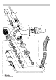

HEAD ASSEMBLY
Using the pins of the combination spanner*, unscrew stroke adjustment locknut 12.
Withdraw stroke adjustment locknut 12, air motor casing 3, spring 13, movement pivot 22, shim adjustment ring 23, piston 24 and
lip seal 25.
Grip the flats on the air motor casing 3 in a vice fitted with soft jaws and with a spanner* separate the air motor assembly from
the piston 24. Spring 13 and stroke adjustment locknut 12 can now be removed from air motor casing 3.
Using circlip pliers* remove circlip 26 and extract lip seal 46.
From the air motor casing 3 remove centre connector 1 using an Allen key* and extract spring 2, ball 4 and pushrod 5.
Reassemble in reverse order of dismantling, observing the following:
Use nylon bush* and pusher* to fit lip seal 46 into its housing.
Use circlip pliers* to fit circlip 26.
Insert metal bush* into handle 28.
Fit lip seal 25 onto piston 24.
Screw bullet* onto piston 24 to ease insertion of lip seal 25 into the handle.
Insert piston 24 into the handle through the metal bush*, then remove the bush* and bullet* from piston.
11
M A I N T E N A N C E
Every 500000 cycles the tool should be completely dismantled and components replaced where worn, damaged or when recommended.
All ‘O’ rings and seals should be replaced with new ones and lubricated with Moly Lithium grease EP 3753 before assembling.
I M P O R T A N T
Safety Instructions appear on pages 2 & 3.
The employer is responsible for ensuring that tool maintenance instructions are given to the appropriate personnel.
The operator should not be involved in maintenance or repair of the tool unless properly trained.
The airline must be disconnected before any servicing or dismantling is attempted unless specifically instructed otherwise.
It is recommended that any dismantling operation be carried out in clean conditions.
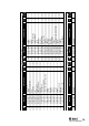
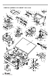
Item numbers in bold refer to the handle assembly drawing and parts list, pages 14 - 15.
Prior to dismantling the tool it is necessary to remove the nose assembly. For simple removal instructions see the nose assemblies section,
pages 8 - 9.
Remove bleed screw 32 and washer 31 and drain oil from tool.
For total tool servicing we advise that you proceed with dismantling of sub-assemblies in the order shown below.
To disconnect the oil hose 46 and air delivery and return hoses 45 from the tool, disengage spiral protection sleeve 47 from sleeve 39
and lower sleeve 39 to gain access to the hoses. Disconnect air hoses by pushing and releasing the quick release connectors. Using
two spanners, undo oil hose 46 at connector 38 leaving the connector attached to the handle of the tool. Remove the tool.
Remove the nose equipment from the tool by loosening the nose tip locknut and unscrewing the nose tip. Unscrew nose casing 33, and
with the aid of spanners* remove the components of the nose assembly. Remove the two air tubes 48 from connectors 1.
■
■
■
■
■
■
■
■
■
■
■
■
* refers to items included in the Avdel service kit. For complete list see page 10.