ADPRO ® FastTrace TM Installation & User Manual for 5, 10 and 20 Channel Models Part No. 201172.
Introduction ADPRO FastTrace is an advanced, high performance digital video and audio recorder optimised for remote search and playback. Available in a number of models with either 5, 10 or 20 video inputs, ADPRO FastTrace provides outstanding transmission speed and picture quality for remote security and surveillance applications where secure, event-driven recording from multiple cameras onto digital data storage disks is required.
Copyright & Tradename Statement Introduction Copyright The ADPRO FastTrace hardware, firmware and accompanying written materials are subject to copyright. Unauthorised copying of the firmware or the written materials is expressly forbidden. You may be held legally responsible for any copyright infringement. Tradename statement ADPRO is a registered trademark of Vision Systems Limited. ADPRO FastTrace is a trademark of Vision Fire & Security.
Liability Introduction Summary of Limitation of Liability for Vision Fire & Security. This ADPRO Product must only be installed, configured and used strictly in accordance with the General Terms and Conditions and the Installation and Setup Manual available from Vision Fire & Security Pty Ltd. You acknowledge that you have read and agree to those terms and conditions.
Warranty Introduction You acknowledge that this is a summary of warranties and you have read and agree to the General Terms and Conditions. Capitalised terms below are defined in the General Terms and Conditions. Vision Fire & Security warrants that the ADPRO® Product will conform to its Specifications and perform its designed function during the Warranty Period.
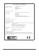
Introduction DECLARATION OF CONFORMITY Manufacturer's Name: Manufacturer's Address: Vision Fire & Security Pty Ltd. 14 Park Way Technology Park Mawson Lakes SA 5095 Australia. declares, that the product(s): Product Name: Model Number: ADPRO FastTrace Multi-Site Video Security System AFT-5005-X-Y AFT-5020-X-Y AFT-5010-X-Y X = Number of Hard Disk Drives between 1 - 4. Y = Number of Video Compression Engines between 1 - 4. Product Options: All meet the Standards detailed below.
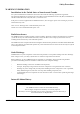
Safety Procedures WARNING INFORMATION Installations in the United States of America and Canada For systems installed in the United States of America and Canada the following requirement is applicable: All equipment installations are required to be in accordance with the National Electrical Code (NEC) ANSI/NFPA 70 and the Canadian Electrical Code (CEC) Part 1, CAN/CSA C22.1.
Safety Procedures WARNING Connection to Other Equipment All interface ports on the ADPRO FastTrace must be only connected to other equipment or systems that are Safety Extra Low Voltage (SELV) rated. Failure to do so will invalidate the electrical safety approval and may cause injury or loss of life. SAFETY WARNING The ADPRO FastTrace is a Class 1 electrical product and must always be connected to a grounded power outlet. Always ensure that ADPRO FastTrace is installed adjacent to a grounded power outlet.
Table of Contents 1 1.0 Installation ................................................................................................................................................................. 1-1 1.1 Unpacking the ADPRO FastTrace ......................................................................................................... 1-3 1.2 Physical Location ..................................................................................................................................... 1-3 1.
Table of Contents 2.3.2 2.3.3 2.3.1.3.2 Daylight Saving ................................................................................................... 2-13 Communications ................................................................................................................... 2-13 2.3.2.1 Ethernet Properties .............................................................................................. 2-14 2.3.2.1.1 IP Address for this Unit...................................................
Table of Contents 2.3.4 ADPRO FastTrace, Issue 5 2.3.3.5.5.8 Configure Transaction Data ................................................................................ 2-32 2.3.3.5.6 Transparent Data Port.......................................................................................... 2-32 2.3.3.5.6.1 Baud Rate ............................................................................................................ 2-33 2.3.3.5.6.2 Parity......................................................
Table of Contents 2.4 2.3.4.6.3 Entry Path Zone(s)............................................................................................... 2-51 2.3.4.6.4 Exit Path and Delay ............................................................................................. 2-52 2.3.5 Maintenance .......................................................................................................................... 2-52 2.3.5.1 Temperature Monitor.........................................................
1.
Installation 1.1 Unpacking the ADPRO FastTrace After unpacking the ADPRO FastTrace, carefully check for any sign of damage. Any damage should be reported before installation to your supplier or to Vision Fire & Security directly.
Installation • 1.3 Environment - Choose an inside location that is cool and dry. Do not mount the ADPRO FastTrace anywhere near machinery that generates heat, toxic fumes and dust. Do not mount the ADPRO FastTrace in close proximity to sources of radio frequency or other electromagnetic radiation. These include radio transmitters (both fixed and portable), electric motors, refrigeration or air conditioning systems and high power or multiphase switching equipment.
Installation 1.
Installation INPUT-OUTPUT • GP SERIAL 1 - (9-pin D - Male) - RS-232 serial port with maximum 38,400 bps data rate • GP SERIAL 2 - (9-pin D - Male) - RS-232 serial port with maximum 38,400 bps data rate • PTZ - (9-pin D - Male) - RS485, for connection to camera stations. Protocol is dependent on the camera station type and model • DATA - (9-pin D - Male) - RS-232 data port with a maximum 57,600 bps.
Installation CONFIGURATION SWITCH ON 1 2 3 4 5 6 7 8 9 10 11 12 * * * * * * NOTE - Factory setting - DO NOT change (12-11) Factory Set ON, ON (10) VIDEO STANDARD ON = RS170 (NTSC) OFF = CCIR (PAL) (9) GP Serial 2 ON = ATM OFF = Debug (8) PTZ PORT TERMINATION ON = RS485 with 120 ohm termination OFF = RS485 without termination (7) COMMS 2 PORT OPERATION ON = DIRECT CONNECT OFF = NORMAL (6) Factory Set OFF (5) PTZ PORT ELECTRICAL INTERFACE ON = RS422 OFF = RS485 (4) Factory Set OFF (1-3) Factory Set OFF
Installation 1.5.1.1 FCC Advice for Installers and Users in the United States ADPRO FastTrace equipment has been tested and found to comply with the limits for a Class A digital device, pursuant to part 15 of the FCC Rules. These limits are designed to provide reasonable protection against harmful interference in a residential installation.
Installation 1.7 Setting the Video Standard ADPRO FastTrace can be set to operate using either PAL (CCIR) or NTSC (RS170) video standards. Once a standard has been selected, all video inputs and the Monitor output (Composite video) will be configured to use the same standard. To set the required video standard, use the Configuration DIP switch on the rear panel. Configuration Switch # 10 ON = NTSC OFF = PAL NOTE To be configured correctly, this switch must be set before power on. 1.
Installation 1.8.1 Video Input Requirements To ensure high quality images, the ADPRO FastTrace must synchronise correctly to the incoming video signal for the selected video standard. For synchronisation to occur the following conditions must be met: • the synchronisation pulse amplitude at each video input must be within the range of 0.2 volts to 0.4 volts, • the peak video amplitude with reference to the black level (ie.
Installation 1.10.1 COMMS 1 COMMS 1 is a serial communications port and is used to connect to modems and terminal adaptors to support PSTN and ISDN links at data rates up to 230Kbps.
Installation 1.10.3 NETWORK Port Connection to an IEEE 802.3 Ethernet Local Area Network is via the NETWORK port. ADPRO FastTrace supports connection to 10baseT and 100baseT wiring systems. IMPORTANT NOTE To ensure correct network connectivity, please ensure ADPRO FastTrace is connected to the network before being powered on. This enables the ADPRO FastTrace unit to detect the correct network speed (10BaseT or 100BaseT). A network address is required for correct operation over a network.
Installation NOTE It is important that a gateway address is only entered if a gateway is present. Configuring the ADPRO FastTrace via the Ethernet connection is further discussed in the Setup Section (refer to Section 2.0). ADPRO WEBSITE For information regarding IP addressing when connecting through a network firewall, please refer to the Tech Tips page under the literature section on the ADPRO website at: http://www.adpro.com.au or contact your nearest ADPRO distributor for a copy. 1.10.
Installation The pinouts for the 9-pin D male connectors are shown. PIN 1 2 3 4 5 6 7 8 9 SIGNAL DCD RXD TXD DTR GND DSR RTS CTS RI DESCRIPTION Carrier Detect Receive Data Transmit Data Data Terminal Ready Ground Data Set Ready Request to send Clear to send Ring Indicator Table 1-4 - GP Serial port pin outs 1.12 PTZ Port Telemetry stations are used for the control of cameras with Pan/Tilt/Zoom (PTZ) hardware.
Installation 1.12.1 PTZ Port Setup The following points are applicable to the PTZ port. • Telemetry stations are connected via a 9-pin D connector, marked ‘PTZ’ • RS485 control links allow cable lengths of up to 1000 metres • Up to 20 (identical) telemetry stations can be connected to one ADPRO FastTrace Use the following guidelines when connecting and setting up a telemetry station.
Installation . ADPRO WEBSITE For information regarding connection and features of specific telemetry station, please refer to the literature section on the ADPRO website at: http://www.adpro.com.au or contact yours nearest ADPRO distributor for a copy. 1.13 Alarm Inputs The ADPRO FastTrace Model 5020 has thirty external Alarm Inputs, all with selectable tamper detection configurations (Model 5005 and Model 5010 have twenty).
Installation WARNING DO NOT attempt to solder directly onto the connector pins, as this may cause heat damage to the connector housing or to the interface PCB.
Installation 1.14 Control Outputs Control Outputs are used to control (switch on or off) external (third-party) equipment connected to the ADPRO FastTrace. NOTE Each Control Output can be set to be active (switch on) when an alarm event is active on the corresponding channel or to respond to remote control via Video Central. The Control Outputs can be used to initiate control of equipment such as lights, sirens, gates and control equipment. 1.14.
Installation Figure 1-9 - External Relay - Typical output circuit 1.15 Mode Select Input The way an ADPRO FastTrace operates its recording and alarm handling features can be changed by using up to four (4) different operating ‘modes’. The parameters that define a particular mode of operation, such as recording rate and alarm responses, are configured by using the FastTrace User Settings Menu.
Installation 1.17 General Alarm Relay Output A Form C single pole changeover contact set is available on the rear panel. If configured to do so, the General Alarm relay activates while the ADPRO FastTrace has an alarm active. The contacts will remain in the changeover condition until all alarms are reset.
Installation Audio Connector Pin Function Line Level Audio Local Speaker Local Microphone Signal Pin Specifications Output 0 1 Common Input 2 3 Unbalanced, impedance 600 ohm Nominal voltage level = 315mVrms 0V Unbalanced, impedance >6K ohm Nominal level = 10mVrms to 400mVrms Ground Speaker (+) Speaker (-) 4 5 6 Ground Microphone (+) Microphone (-) 7 8 9 Balanced, impedance = 8 ohm Nominal output power = 1W Total harmonic distortion < 5% Differential impedance > 3K ohm Single ended impedance
2.
Setup 2.1 Power Up The green Power and the red Status LED’s on the front panel are lit as soon as power is applied to the unit. The ADPRO FastTrace immediately starts to perform internal tests to ensure both software and hardware integrity. While the internal tests are executing, the Fault Relay is de-energised and the red Status LED is lit, or flashing. The Status LED will be ON during the initial stages of bootup then start flashing when the system is being initialized.
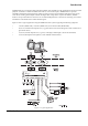
Setup 2.2.1 Local Setup When first configuring the ADPRO FastTrace for operation at a remote site, it is recommended that a local (direct) connection is made so that camera position and alarm parameters can be conveniently checked. Figure 2-1 shows the items needed for a direct connection.
Setup 2.2.1.1 Installing ADPRO Video Central Lite Start the PC and insert the ADPRO Video Central Lite CD-ROM. If the Autorun feature is used, the ADPRO Video Central Lite setup wizard will load. If autorun is not enabled, find and run the CD-ROM file named cdmenu.exe. Select the Install ADPRO Video Central Lite option. Follow the setup wizard instructions and accept ALL the default settings. Exit from the menu when finished, but leave the CD-ROM in the drive.
Setup NOTE To change the settings on the COM ‘n’ port: Windows NT: Control Panel / Ports / COM ‘n’ Windows 2000: Control Panel / System / Hardware / Device Manager / Ports / COM ‘n’ / Port Settings. Windows XP: Control Panel / Performance and Maintenance / System / Hardware / Device Manager / Ports / COM ‘n’ / Port Settings. IMPORTANT NOTE For the serial port to operate correctly, a special ‘null-modem’ software driver needs to be installed.
Setup The Default check box in the communications section sets the currently selected communication type as the default for that site. When connecting to a site, this is the connection type it will use as the default, unless another is selected from the drop down list. 2.2.1.1.3 Optional Network Connection Settings If using the PC’s network port (instead of the serial port), a crossover network cable (Cat 5) must be used between the PC and the ADPRO FastTrace.
Setup 2.2.1.1.4 Connecting to the ADPRO FastTrace Ensure the ADPRO FastTrace has completed its start-up checks (as indicated by the red status light going off). • From the Connection menu, click the Connect to Site option • Select the site named FastTrace default site and click the OK button Accessing the ADPRO FastTrace ‘User Settings’ menu: Setup parameters and configuration options for the ADPRO FastTrace can now be modified via the User Settings menu.
Setup NOTE The setup program will not allow invalid parameters to be saved. For example, should you receive a message asking for a correct Ethernet Gateway address to be entered, either enter the correct value or delete the invalid entry. 2.2.1.1.
Setup 2.2.2 Leaving User Settings When changes to the setup parameters are completed, options available are: 2.2.3 • Save to FastTrace Changes are uploaded and stored in the ADPRO FastTrace NVRAM permanent memory and are immediately available for use. • Save to File Current settings are saved to file on the Video Central PC and are available for later use. • Load from File A pre-saved configuration file can be retrieved from the Video Central PC and edited.
Setup 2.3.1 • If the selected settings file is incompatible, that is, the loaded file is newer than remote unit’s settings, then the following dialogue will be displayed: • To rectify this, the User will need to either use an older setup file, or upgrade the ADPRO FastTrace. Site Details Figure 2-4 - Site Details menu Note that some options for a category can be affected by the status of other setting(s) and may be unavailable (shown ‘ghosted’).
Setup 2.3.1.1 Site Name Each ADPRO FastTrace must have a unique Site ID. The maximum site ID alpha-numeric length is 9 characters. Note that the ‘local’ Site ID entered here must match a Site ID entry in the ADPRO Video Central Lite Site List. The default Site ID is ‘FASTRACE’. 2.3.1.2 Passwords To control access to ADPRO FastTrace’s stored images, alarm reporting features and the setup menus, different password types can be set to control the access level required by a particular type of user.
Setup WARNING Changing the current time/date setting is done via the ADPRO Video Central Lite when it is connected on-line to an ADPRO FastTrace unit. When changing the current time backwards (i.e. the displayed time is ahead of the correct local time), use 60 second steps (or less) to move back to the correct time. Entering a value greater than 60 seconds will result in lost data. This warning only applies to changes to the value for current time and does not apply to Time Zone or Daylight Saving changes.
Setup 2.3.2.1 Ethernet Properties A direct connection to a 10BaseT or 100BaseTX Ethernet network can be made via the Ethernet Port. The current IP Address of the unit is shown for clarification. To change this address, the Subnet Mask or Default Gateway address, click the Configure button. Ethernet settings are used to configure the TCP/IP parameters for a LAN or WAN connection.
Setup 2.3.2.1.3 Default Gateway Factory Default No Gateway For communication with ADPRO Video Central Lite located on another network, the ADPRO FastTrace must be given the address of the first host device on the route to the destination network (and vice versa). The Default Gateway is the address of the host to which the ADPRO FastTrace sends packets that are destined for the remote network. If a default gateway is not specified, communication is limited to the local network.
Setup NOTE The COMMS 2 port can be used for direct connections to a PC for local setup and for software upgrades. The Serial Communications Port 1 Settings and Serial Communications Port 2 Settings menus allow the operating parameters of the two serial ports to be configured to match the model of modem or terminal adaptor used. Figure 2-6 - Serial Communication Port Settings Menu 2.3.2.2.
Setup 2.3.2.2.2 Line Type Options: Factory Default: Dial, Leased Line. Dial The Dial option is used for analogue (PSTN) or digital (ISDN) networks where the connection is usually made by dialling a particular telephone number.These lines may be routed via a switchboard or PABX system. Set this option to Leased Line if the system is connected via a dedicated (leased) line.
Setup 2.3.2.2.6 Initialisation String This option is used to enter additional Hayes AT commands (in ASCII format) that may be required to configure a modem or Hayes compatible RS232 terminal adaptor to initiate (or activate) a particular product feature or setting. Refer to the User Manual of the particular device to obtain the required Hayes AT commands.
Setup 2.3.2.2.9 Enable PAP Factory Default: No Set this checkbox to enable Password Authentication Protocol. PAP will authenticate the remote system during the PPP negotiations. The valid username and password are defined by the fields of PPP Username and PPP Password. 2.3.2.2.10 PPP Username Option: 20 characters maximum. The Username (or Site Name) that will be provided by PPP when negotiating a serial IP connection. It is only required when PAP is enabled.
Setup 2.3.2.3 Advanced Communication Properties Base Port Number: Options: Range is 2049 to 65536 Factory Default 15000 The Advanced Communication Properties option defines the Base Port Number used for communications with the PC running ADPRO Video Central Lite software. The default value = 15000 and should not be changed unless a conflict occurs due to a network connection of other third-party equipment.
Setup 2.3.2.3.2 Main Communications Link Options: Factory Default: Ethernet, Serial Communications 1, Serial Communications 2 Ethernet The Main Communications Link sets the communication strategy to be employed for automatically sending Alarm status and associated images to ADPRO Video Central Lite. The Outgoing Communications strategy can be based on using the unit’s Ethernet port or one of the two Serial Communications ports.
Setup 2.3.2.3.4 Connection Separation (seconds) Options: Factory Default: Range 5 to 300 5 Connection Separation is a time interval that the ADPRO FastTrace waits between successive attempts to establish a communication link. The Connection Separation time starts from the end of the last Connection Attempt and can be set in 1-second increments. It is important that the chosen value takes into account any delays introduced by the network itself or routers, gateways etc.
Setup 2.3.3 Connected Equipment The Connected Equipment menu provides a number of sub-menus to configure the settings that the ADPRO FastTrace will use when interacting with external equipment such as video cameras, microphones/speakers, alarm inputs and control output devices as well as the local monitor and alarm relay contacts. Figure 2-9 - Connected Equipment menu 2.3.3.
Setup 2.3.3.
Setup The status of a Channel is shown by a small icon to the left of the Channel number. • A Channel is free when the ‘empty’ icon is shown next to the number • The Connect button is used to set the status of a channel and enable the video for recording and viewing. When enabled, other details about this camera can be modified • To temporarily disable the use of a camera and any alarms that may be generated by it, the Disconnect button is used.
Setup 2.3.3.3.5 Use Activity Detection The ADPRO FastTrace can be setup to respond to changes that occur within the field of view of a camera. This feature is used to trigger an alarm if activity is detected by a certain camera in an area not normally expected to have activity. To help configure the Activity Detection feature, the sensitivity to movement and the amount of time that movement occurs, can be programmed. 2.3.3.3.
Setup When the option is selected a display of the selected camera's image is shown along with three buttons. The current options available are: • Set All Places the maximum number of detection zones over the video image. All zones are active. The maximum number of zones for PAL systems is 396 zones (22 wide x 18 high), NTSC systems have 330 zones (22 wide by 15 high) • Clear All Removes all currently assigned zones.
Setup 2.3.3.4 Monitor A local monitor can be connected to the ADPRO FastTrace and used to display a number of camera views in a sequence. Set the Local Monitor Connected checkbox if a sequence monitor is to be used. Click the Configure button to setup the sequence. 2.3.3.4.1 Sequence List The list defines the sequence (order) in which camera images are presented on the monitor. The sequence list can show up to 20 cameras and the checkbox next to the camera number will select that camera for inclusion.
Setup The status of a channel is shown by a small icon to the left of the channel number. A channel is free when the ‘empty’ icon is shown next to the number. Once a channel has been selected, the Configure button is used to access the Transaction Device ‘n’ Settings menu. The menu is used to define the behaviour of each device and a number of fields are available to set various properties. 2.3.3.5.1 Device Name Option: Default: 16 characters maximum.
Setup 2.3.3.5.2 Protocol Options: Default: NCR ATM, AVE VSSI-PRO NCR ATM Select the type of protocol used by the Transaction Device connected to the ADPRO FastTrace. 2.3.3.5.3 Communications Link Options: Default: TCP/IP (Ethernet), Direct Serial Depends on the Protocol selected. The Protocol option defines the communications medium that is used to communicate with the device.
Setup 2.3.3.5.5.2 Central IP Address Factory Default 0.0.0.0 The Central IP Address is used to identify the TCP/IP network node to which the normal transaction data from the ATM/POS terminal is sent. This is normally a bank or financial institution network (gateway) port. The address is divided into four (4) parts separated by a (.), each part with a decimal range value from 0 to 255.
Setup 2.3.3.5.5.7 Flow Control Options: Default: Hardware, None None Sets the type of Flow Control used to transfer data between the GP Serial interface and the Transaction Device. It can be set to either Hardware or None. 2.3.3.5.5.8 Configure Transaction Data Clicking the Configure Transaction Data button displays the dialog box shown below. Selecting an unused Field number and pressing Configure allows a Name to be entered for the field via the Transaction Data Field Name Settings dialog box.
Setup If users highlight the Transparent Data Port in the Category column the above dialog will be presented. To enable the Transparent Data Port check the Transparent Data Port Connected option. The Connection Port drop down list displays the Data Port that is currently allocated in the ADPRO FastTrace system. The Connection Port option is: Data Port. Select the Configure … button and the following dialog will appear 2.3.3.5.6.
Setup 2.3.3.5.6.2 Parity Options: Default: None, Odd, Even None Sets the Parity used when transferring data locally between the transparent data port and the RS-232 Device. 2.3.3.5.6.3 Data Bits Options: Default: 5, 6, 7, 8 8 Sets the number of Data Bits used to transfer data between the transparent data port and the RS-232 Device. It can be set to either 5, 6, 7 or 8 data bits. 2.3.3.5.6.
Setup Figure 2-11 - Alarm Contacts List When the Configure button is used, changes to the Alarm Contact Settings can be made. 2.3.3.5.7.1 Alarm Input Name Option: 16 characters maximum. Enter the name to be associated with this Alarm Input. 2.3.3.5.7.2 Alarm Type Options: Default: Normally Open (N/O), Normally Closed (N/C), N/O SEOL, N/C SEOL, N/O DEOL, N/C DEOL Normally Open The ADPRO FastTrace can be programmed to trigger an alarm when the contacts associated with a channel change state.
Setup 2.3.3.5.7.3 Hold Time Options: Factory Default: When active, 2 sec, 5 sec, 10 sec, 30 sec, 60 sec. 10 seconds When there is a requirement that two (related) alarm inputs must be active before an alarm is activated (known a double knock alarm activation), the Hold Time option sets the time ‘window’ for the second alarm input to occur. If the second alarm input is not activated within the Hold Time period, no alarm event will be generated.
Setup Figure 2-12 - Control Output Settings Menu When the Configure button is used, the following settings can be made. 2.3.3.5.8.1 Control Output Name Option: 16 characters maximum. Enter the 16 character name to associate with this output. The name can be displayed when viewing video from a camera input associated with this control output. 2.3.3.5.8.2 Default State Option: Default: Normally Open, Normally Closed Normally Open Defines the operational state of the Control Output when not asserted.
Setup 2.3.3.5.8.4 Disconnect Operation Option: Default: Reset, Latch Reset Defines the operational state of the Control Output after a user has disconnected from the ADPRO FastTrace. • the Reset option returns the output to the condition defined by the Default State. • the Latch option causes the Control Output to remain in its current (operated) condition. 2.3.3.5.9 Audio The Audio menu configures the ADPRO FastTrace audio channel features.
Setup 2.3.3.5.9.3 Audio Input Gain Options: Factory Default: Range 0 to 15 2 Choose a volume level between 0 (lowest) and 15 (highest) to suit the operational environment. 2.3.3.5.9.4 Audio Out Volume Options: Factory Default: Range 0 to 15 2 Choose a volume level between 0 (lowest) and 15 (highest) to suit the operational environment. 2.3.4 Operational Behaviour The Operational Behaviour menu is used to configure an ADPRO FastTrace’s: 2.3.4.
Setup 2.3.4.1.2 Event (Recording Retention Time) Range: Default: more than the Normal Retention time (mentioned above) to 1000 60 days Event Recording Retention Time sets the maximum number of days that the ADPRO FastTrace will attempt to store images that have been recorded as a result of an (alarm) event. Once the Event time has expired, the disk space will be reallocated for new images.
Setup 2.3.4.2.2 Mode Selection Options: Default: Use External Input, Use Calendar Use External Input OPERATIONAL NOTE The choice of a Mode Selection option will apply to ALL modes. The Use External Input to Change Modes option is used to configure switching between two modes via the use of the Mode Select Input on the rear panel of the unit (Pin 6 of the Audio Switcher connector). Of the four available modes, any two can be assigned.
Setup • • • Video Capture Event Triggers Event Response Select the required tab to access the settings for the camera. IMPORTANT NOTE The maximum recording rate of the ADPRO FastTrace is 25 ips (PAL) and 30ips (NTSC) per compression card (at CIF resolution). The rate is an aggregate of all recording channels and it should be noted that the recording rate of some channels may slow down during alarm conditions to ensure alarm images are recorded. 2.3.4.4.
Setup 2.3.4.4.3 Capture Settings - Defaults The following table shows the Capture Settings defaults: Capture Setting Continuous Event Continuous & Event Normal Pre-Event Event Normal Event Quality (1-7) 4 6 6 4 6 Record Rate (ips) 1 1 5 1 5 Capture Duration (sec) -- 10 30 -- 30 Quality Range: 1 to 7 Sets the quality level of recorded images. A value of 1 sets the lowest recording quality and 7, the highest.
Setup 2.3.4.4.4 Event Triggers Users can choose from two triggering methods to select ‘how’ a channel is activated for an alarm event. The Alarm Logic option is used the setup the logical order to which Alarm Inputs are treated before an alarm event is declared to be ‘valid’. 2.3.4.4.4.1 Alarm Logic Options: Default: When ANY input occurs, Only when ALL inputs occur When ANY input occurs The When ANY input occurs setting will declare an alarm when any input is active (logical OR function).
Setup 2.3.4.4.5.2 Dial Out on Event The Dial out on event option is used to define whether the ADPRO FastTrace will attempt to connect to ADPRO Video Central Lite if and when this camera records an event. If the Dial out only when secure checkbox is selected, the ADPRO FastTrace will only attempt a remote connection if the unit is set into the Secure state of operation. Refer to Section 1.17. 2.3.4.4.5.
Setup NOTE As there is only one audio channel, Live Audio has priority over Alarm Audio and Alarm Audio has priority over normal recording. 2.3.4.5 Multi-Screen Live Behaviour This feature allows the User to view multiple channels in Live Mode simultaneously, in preset configurations. ADPRO Video Central V8.04 or higher and ADPRO FastTrace system software version 1.02 or higher is required to be installed on the transmitter for Multi-Screen to be available.
Setup 2.3.4.5.1 Guard Tour Settings To select which cameras are included in the Guard Tour click on the configure button. Check the cameras needed in the Guard Tour and also enter a Dwell Time. 2.3.4.5.2 Selectable Multi-Screen Settings The user can create and configure different Multi-Screen profiles according to their preferences. The following screen splits are supported: Single Screen, 4-way, 7-way, 9-way, 10-way, 13-way, 16-way and 20-way.
Setup 2.3.4.5.2.1 Adding a new profile • click the New Profile button • A new entry New Profile will be added to the General Profiles listbox. If a profile with this name already exists, the name will be ‘New Profile ’ • The cameras list box will show a list of all connected cameras (in numerical order), and Layout control will have the smallest split size. Video Quality value will default to ‘Same as Guard Tour’. For bes update rates, quality 6 or lower is recommended. 2.3.4.5.2.
Setup 2.3.4.5.2.5 Adding a camera from the Cameras listbox to the Profile Layout control • Highlight the camera entry in the Cameras listbox • Click on [>] button to add the selected camera to the layout. As a result of this: • The selected camera will be removed from the Cameras listbox • The selected camera will be added to the Profile Layout. If there are vacant spaces in the Layout, the camera will be placed in the first available space.
Setup 2.3.4.5.2.6 Modifying a Profile Layout 2.3.4.6 • The placement of cameras within the layout can be altered at any time using Drag & Drop operations. • This reshuffle will always involves two cameras swapping their placements, as Layout control will not allow a camera and a vacant place to swap locations.
Setup 2.3.4.6.1 Entry Path and Delay Alarms and their associated images originating from the Entry Point and Entry Path Zones are held as pending and then discarded if the system is placed into Access mode before the Entry Path Delay expires. If the Entry Path Delay expires before the system is placed into Access mode, then any Alarm Input will be processed immediately. Note that any other alarm that is not in the Entry Path Zones list, will be processed immediately. 2.3.4.6.
Setup 2.3.4.6.4 Exit Path and Delay When the ADPRO FastTrace is ‘sealed’ (i.e. set into the Secure mode), alarms from sensors in the Exit Path Zones will occur as the route is used. These alarms are ignored until the end of the Exit Path Delay period. However, any other Alarm that is not in the Exit Path Zones list, will be processed immediately. 2.3.5 Maintenance ADPRO FastTrace V1.02 incorporates new fault reporting functionality.
Setup 2.3.5.1 Temperature Monitor There is an option present to enable the reporting of a high temperature event to Video Central and to activate the FastTrace fault relay. The default selection is OFF. If High Temperature Management is enabled: When the internal temperature of any disk drive rises above the high temperature threshold, FastTrace will initiate an over-temperature condition and report this to Video Central. The FastTrace fault relay will activate during the overtemperature condition.
Setup 2.4 Event Log The ADPRO Video Central has the capability to download the contents of a remote ADPRO FastTrace ‘site event log’ for review. This feature is useful when carrying out system diagnostics, or investigating problems associated with event reporting from the site. The log can be seen by selecting either the Site Log menu item from the Connection menu, or by selecting the Download Transmitter Log icon from the Site Actions fly-out menu.
3.
Specifications 3.1 ADPRO FastTrace Version 1.02 An ADPRO FastTrace system consists of one or more Multi-Site Video Security System at a remote site and a PC running the ADPRO Video Central Lite software at a monitoring site. Connection is via a TCP/IP based Ethernet network or dial-up or leased telephone lines.
Specifications Function Description Network Port 1x Ethernet 10BaseT / 100BaseT compatible supporting TCP/IP. RJ-45 connector. Serial Communication Interface 2x V.24 asynchronous interfaces - 8 data bits, 1 stop bit, no parity, programmable data rate steps from 9600 to 230400 bps. 1x 9 pin male D, 1x 25-pin male D. Configured as a DTE device. Supports Hayes (AT) compatible ISDN and PSTN modems in dial or leased line configuration. Support for Multilink PPP or V.120 data protocol over ISDN.
Specifications Function Description Warranty 24-months on all components except Hard Disk Drive (HDD) units where manufacturers warranty and conditions apply.
Specifications 3.2 ADPRO Video Central Lite Version 8.04 Function Description Operating System Windows XP (Professional Edition) or Windows 2000 (Professional Edition) preferred Windows NT 4.
INQUIRIES AUSTRALIA Vision Fire & Security Private Bag 215 495 Blackburn Road Mount Waverley Vic 3149 Australia Telephone +61 3 9211 7300 Facsimile +61 3 9211 7202 Toll Free 1800 700 203 Technical Support 1800 554 664 THE AMERICAS Vision Fire & Security 700 Longwater Drive Norwell Massachusetts 02061 USA Telephone +1 781 740 2223 Facsimile +1 781 740 4433 Toll Free 800 229 4434 EUROPE & THE MIDDLE EAST Vision Fire & Security Vision House Focus 31 Mark Road Hemel Hempstead Herts HP2 7BW UK Telephone +44 (0