TCPIP232 POS / ATM Ada pter Adapter ATM TCP/IP Interface Stand alone or with VSSI-Pro/VSI-Pro/VSI-Pro MAX POS TCP/IP Interface Stand alone or with VSI-Pro /VSI-Pro Max OPERATION MANUAL February 2013
TCPIP232 CAUTION! RISK OF ELECTRICAL SHOCK! TO PREVENT ELECTRIC SHOCK, DO NOT REMOVE THE COVER. DO NOT EXPOSE THE EQUIPMENT TO RAIN OR MOISTURE. NO USER SERVICEABLE PARTS ARE INSIDE. REFER SERVICING TO QUALIFIED PERSONNEL. WARNING! THIS EQUIPMENT GENERATES, USES, AND CAN RADIATE RADIO FREQUENCY ENERGY AND IF NOT INSTALLED AND USED IN ACCORDANCE WITH THE INSTRUCTION MANUAL MAY CAUSE INTERFERENCE TO RADIO COMMUNICATIONS.
CONTENTS BOOT MENU.................................................................................................................................5 ITCPIP232 ATM/POS...................................................................................................................7 TCPIP232 Connections.................................................................................................................7 TCPIP232 Hardware Configuration...............................................................
FIGURES Figure 1: Stand Alone Connection...............................................................................................7 Figure 2: VSSI-Pro Interface........................................................................................................7 Figure 3: VSI-Pro or VSI-Pro Max Interface..............................................................................8 Figure 4: AVE RS485 Network Interface..................................................................................
BOOT MENU TCPIP232 is able to select upon boot u p to the “TCPIP232 ATM/POS” , “VSS 3700” or “UPDATE FIRMWARE” by connecting the PC/DVR cable (021-037-SF). The connects from the TCPIP232 adapter to your laptop. Power up the TCPIP232 RS-232 Port and your laptop and run a serial communications program like Hyper Terminal at baudrate 19200,n,81 with VT100 emulation. Press ESC key (1BH) , [ (5Bh) and S (53H) to enter to the BOOT Menu. You will see the following “Boot Menu”.
VSS 3700 By selecting the VSS 3700 you will enter to the VSS 3700 operating mode. Wait for the TCPIP232 to reboot and show the message as below. You will then be ready to use the TCPIP232 for the Micros VSS 3700 UDP Interface. (refer to page 36 for operation and programming details) TCPIP232 Micros VSS 3700 Listening 192.168.2.
TCPIP232 ATM/POS The TCPIP232 Interface is designed to capture ATM or POS transactions on a Ethernet LAN system and then convert captrued transactions to a serial port to interface with VSSIPro (ATM Synchronous Serial Interface), VSI-Pro Max or VSI-Pro to overlay the text on the video and export the data in formated ASCII to other devices like a DVR. It also allows full programming of the TCPIP232 via on-screen interative menu of the above devices.
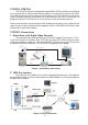
3. VSI-Pro or VSI-Pro Max Interface The VSI-Pro and VSI-Pro Max supports Text Insertion and programmable gray scale and background of text inesertion and can be programmed via the Onscreen display for setting the ATM or POS IP in addition to PC Programming of both units. Video IN Camera CAT-5 CAT-5 RS232 Output Video OUT ATM TCPIP232 DVR VSI-Pro/MAX Figure 3. VSI-Pro or VSI-Pro Max Interface 4.
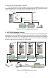
TCPIP232 Hardware Configuration: TCPIP232 hardware operation depends on your network connection. TCPIP232 is able to operate with HUB and Network Switcher. There are 2 hardware configurations: 1. Mirror Mode This Mode supports HUB and Programmable Network Switchers. The user needs to provide a port for TCPIP232 to capture ATM transactions on the HUB and needs to mirror the ATM LAN port for TCPIP232 port to capture data. This kind of switcher we called “programmable network switcher” . 2.
TCPIP232 Setups The user must be careful to unplug the LAN cable from the ATM or POS. The ATM or POS has the protection when there is no comunication between the ATM and Host Server in limited time your ATM will be offline automatically. This peroid is called the “ATM Time Out’. This time out depends on your ATM system. It is approximately 6-10 seconds. Stand Alone Setup Connect the PC/DVR cable (021-037-SF) which comes from the TCPIP232 adapter to your laptop.
INFORMATION SETTING * INFORMATION 0 - INFORMATION 1 - INFORMATION 2 - INFORMATION 3 - EXIT ON ON ON ON INFORMATION SETTINGS INFORMATION This is a user define for additional information in the transaction to display special information. EXIT Exit to main menu.
TIME SYNC SETTINGS * DATE FORMAT MM/DD/YY - TIME SYNC OFF TIME SYNC SETTINGS DATE FORMATP ADDRESS Select date format to be MM/DD/YY , DD/MM/YY or YY/MM/DD TIME SYNC Sync time to the MVDR. EXIT Exit to main menu. SENSE Select type of LAN cable for Straight Through or Cross Over cable if you select AUTO then TCPIP232 will select cable type automatically. TRANSACTION ALARM OFF Off transaction alarm function. MVDR Send serial alarm to the MVDR every time that transaction cause .
CRE Cash Register Express filter format. Connecting diagram and TCPIP232 setting refer to page 25. GILBRACO PASSPORT GILBRACO PASSPORT filter format. Default port at 700 but you can change what ever you want. Connecting diagram and TCPIP232 setting refer to page 30. INFO GENESIS INFO GENESIS filter format. Default port at 7005 but you can change what ever you want. Connecting diagram and TCPIP232 setting refer to page 32. DIGISM 5500 DIGISM 5500 filter format.
TCPIP 232 Connecting Diagram and Detting TCPIP 232 Vonnecting with ATM 1. Connecting diagram Camera Video Coaxial Monitor Router/ Network Switch ATM CAT-5 CAT-5 Video Serial TCPIP232 DVR Figure 6. ATM Stand Alone Tapping Mode Connection Monitor Camera Video Coaxial Router/ Network Switch ATM CAT-5 Video CAT-5 Serial TCPIP232 DVR Figure 7.
2. Select TCPIP 232 Fiter Type for ATM. TCPIP232 SETUP - TCP/IP SETTINGS - INFORMATION SETTINGS - INTERFACE SETTINGS - TIME SYNC SETTINGS - SENSE - TRANSACTION ALARM * FILTER TYPE - WATCHDOG TIMER - EXIT AUTO OFF ATM ON 3. Setting the IP Address in TCP/IP Setting Menu to be an IP of the ATM. TCPIP SETTING * IP ADDRESS 192.168.0.0 - DESTINATION PORT ANY - EXIT 4. Exit from TCPIP 232 setting and back to operating mode. 5.
TCPIP 232 Connecting with EPSON or GENERIC LAN PRINTER. 1. Connecting Diagram Camera Monitor Video Rounter/Network EPSON Printer CAT-5 Video Cash register Serial CAT-5 TCPIP232 DVR Figure 9. EPSON or GENERIC LAN PRINTER Stand Alone Tapping Mode Connection Camera Monitor Video Rounter/Network CAT-5 Video CAT-5 Cash register Serial CAT-5 TCPIP232 EPSON Printer DVR Figure 10.
2. Select TCPIP232 Fiter Fype for EPSON or GENERIC LAN PRINTER TCPIP232 SETUP - TCP/IP SETTINGS - INFORMATION SETTINGS - INTERFACE SETTINGS - TIME SYNC SETTINGS - SENCE AUTO - TRANSACTION ALARM OFF * FILTER TYPE EPSON - WATCHDOG TIMER ON - EXIT 3. Setting the IP Address in TCP/IP setting menu to be an IP of the printer. TCPIP SETTING * IP ADDRESS 192.168.0.0 - DESTINATION PORT ANY - EXIT 4. Exit from TCP232 setting and back to operating mode. 5.
TCPIP 232 Connecting with NCRACS 1. Connecting Diagram Camera Video Coaxial Monitor Router/ Network Switch NCRACS CAT-5 CAT-5 Video Serial TCPIP232 DVR Figure 12. NCRACS Stand Alone Tapping Mode Connection Camera Monitor Video Coaxial Router/ Network Switch NCRACS CAT-5 Video CAT-5 Serial TCPIP232 DVR Figure 13.
2. Select TCPIP232 Fiter Type to be NCRACS. TCPIP232 SETUP - TCP/IP SETTINGS - INFORMATION SETTINGS - INTERFACE SETTINGS - TIME SYNC SETTINGS - SENCE AUTO - TRANSACTION ALARM OFF * FILTER TYPE NCRACS - WATCHDOG TIMER ON - EXIT 3. Setting the IP Address in TCP/IP setting menu to be an IP of NCRACS. TCPIP SETTING * IP ADDRESS 192.168.0.0 - DESTINATION PORT ANY - EXIT 4. Exit from TCP232 setting and back to operating mode. 5.
TCPIP 232 Connecting Diagram with Filter Type Setting as DUMP. 1. Connecting diagram Rounter/Network Switcher ATM CAT-5 Hyper Terminal PC CAT-5 Serial TCPIP232 Figure 15. ATM Dump Data Tapping Mode Connection Rounter/Network Switcher ATM CAT-5 Hyper Terminal PC CAT-5 Serial TCPIP232 Figure 16. ATM Dump Data Mirror Mode Connection Cash Register Hyper Terminal PC Printer CAT-5 CAT-5 Serial TCPIP232 Figure 17.
2. Setting TCPIP 232 in Filter Type as DUMP. TCPIP232 SETUP - TCP/IP SETTINGS - INFORMATION SETTINGS - INTERFACE SETTINGS - TIME SYNC SETTINGS - SENCE AUTO - TRANSACTION ALARM OFF * FILTER TYPE DUMP - WATCHDOG TIMER ON - EXIT 3. Setting the IP Address in TCP/IP setting menu to be an IP of the ATM or Printer that need to capture data. TCPIP SETTING * IP ADDRESS 192.168.0.0 - DESTINATION PORT ANY 4. Open Hyper Terminal program on the PC and setting Set comport at baud rate 19200,N,8,1 Flow control NONE.
5. Select Emulation to be ANSI. 6. Click on ASCII setup button then set ASCII Sending and ASCII Receiving as follows.
7. Click on Tranfer Menu and select Capture Text 8. Locate the file that need to capture.
9. Click Call menu and select call for ready to receive data from RS232. 10. Try to make some transaction from ATM or Cash register and transaction data will appear on Hyper Terminal screen. 11. Click Tranfer menu and seclect Capture Text and click Stop then RAW transaction data will store in the file where that locate in the PC.
TCPIP 232 Connecting with Cash Register Express(CRE) Cash Register Express setting to be Client and Server Connecting Diagram 1. Connecting Diagram Camera Video CRE server PC Rounter/Network Monitor CRE client PC CAT-5 CAT-5 Video Serial TCPIP232 DVR Figure 19. Cash Register Express Tapping Mode Connection Camera Video Rounter/Network Monitor CRE client PC CAT-5 CRE server PC Video CAT-5 Serial CAT-5 TCPIP232 DVR Figure 20.
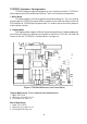
CAM1 CAM3 CAM2 CAM4 CRE CRE CRE CRE Client PC 1 Client PC2 Client PC3 Client PC4 CAT-5 CAT-5 CAT-5 TCPIP232 CAT-5 TCPIP232 TCPIP232 TCPIP232 Rounter/Network Switcher CAM1-4 INPUT RS232 CRE DVR RS485 Hydra/VSI-Pro MAX Master Server PC Figure 21. Cash Register Express Client Server Setting RS485 Network Interface 2. Setting TCPIP 232 in FILTER TYPE to be CRE.
3. Setting the IP Address in TCP/IP setting menu to be an IP of the Cash Register Express server PC. TCPIP SETTING * IP ADDRESS 192.168.0.0 - DESTINATION PORT ANY - EXIT 4. Start cash register express server on the CRE server PC. Then from the login screen select file, go to the security tab select “ Start the DVR Server “. And login to the cash register express. 5. Start cash register express client on the CRE client PC.
6.Setting network environment of the client Cash Register Express network setting by press Option button. 7. Click on “Setup” button(1) and click on “Setup Screen” (2) then Setup Screen setting will appear.
8. Put the IP of Cash Register Expressx server by click on “Hardware” tab(1) and click on “Page2” tab(2) and put the IP of the Cash Register Express (3) that configuration to be Cash Register Express server. 9. Exit from Cash Register Express setting and back to operating mode. 10. Try to make a transaction from Cash Register Express client PC then DVR will be display invoice transaction display on screen along with cash register number.
TCPIP 232 connecting with Gilbraco Passport 1. Connecting diagram Camera Monitor Video Rounter/Network Gilbraco Passport CAT-5 Video CAT-5 Serial TCPIP232 DVR Figure 22. Gilbraco Passport stand alone tapping mode connection Camera Monitor Video Gilbraco Passport Rounter/Network CAT-5 Video Serial CAT-5 TCPIP232 DVR Figure 23.
2. Select TCPIP232 Fiter Type to be GILBRACO PASSPORT. TCPIP232 SETUP - TCP/IP SETTINGS - INFORMATION SETTINGS - INTERFACE SETTINGS - TIME SYNC SETTINGS - SENCE AUTO - TRANSACTION ALARM OFF * FILTER TYPE GILBRACO PASSPORT - WATCHDOG TIMER ON - EXIT 3. Setting the IP Address in TCP/IP setting menu to be an IP of printer. TCPIP SETTING * IP ADDRESS 192.168.0.0 - DESTINATION PORT ANY - EXIT 4. Exit from TCP232 setting and back to operating mode. 5.
TCPIP 232 Connecting with INFO GENESIS 1. Connecting Diagram Camera Monitor Video Rounter/Network INFO GENESIS CAT-5 CAT-5 Video Serial TCPIP232 DVR Figure 25 INFO GENESIS Stand Alone Tapping Mode Connection Camera Monitor Video INFO GENESIS Rounter/Network CAT-5 Video Serial CAT-5 TCPIP232 DVR Figure 26.
2. Select TCPIP232 Fiter Type to be INFO GENESIS. TCPIP232 SETUP - TCP/IP SETTINGS - INFORMATION SETTINGS - INTERFACE SETTINGS - TIME SYNC SETTINGS - SENCE AUTO - TRANSACTION ALARM OFF * FILTER TYPE INFO GENESIS - WATCHDOG TIMER ON - EXIT 3. Setting the IP Address in TCP/IP setting menu to be an IP of printer. TCPIP SETTING * IP ADDRESS 192.168.0.0 - DESTINATION PORT ANY - EXIT 4. Exit from TCP232 setting and back to operating mode. 5.
TCPIP 232 Connecting with DIGISM 5500 1. Connecting diagram Camera Monitor Video DIGISM 5500 CAT-5 Video CAT-5 Serial TCPIP232 DVR Figure 28. DIGISM 5500 Stand Alone Tapping Mode Connection Camera Monitor Video Rounter/Network DIGISM 5500 CAT-5 Video Serial CAT-5 TCPIP232 DVR Figure 29.
2. Select TCPIP232 Fiter Type to be DIGISM 5500. TCPIP232 SETUP - TCP/IP SETTINGS - INFORMATION SETTINGS - INTERFACE SETTINGS - TIME SYNC SETTINGS - SENCE AUTO - TRANSACTION ALARM OFF * FILTER TYPE DIGISM 5500 - WATCHDOG TIMER ON - EXIT 3. Setting the IP Address in TCP/IP setting menu to be an IP of printer. TCPIP SETTING * IP ADDRESS 192.168.0.0 - DESTINATION PORT ANY - EXIT 4. Exit from TCP232 setting and back to operating mode. 5.
TCPIP232 Micros VSS 3700 UDP Interface The TCPIP232 Micros VSS 3700 UDP Interface is used for receiving the UDP messages from Micros Workstations and send the information to the RS232 output in formatted ASCII to a Digital Video Recorder (DVR) which supports text insertion and overlays trasaction information to video or any RS-232 device. The TCPIP232 Micros VSS 3700 can read data from up to 16 Work Stations simultaneously and output all the data using the AVE VSI-ADD protocol.
TCPIP232 Micros VSS 3700 Hardware Configuration: Figure 32. TCPIP232 Hardware Silkscreen Default settings for TCPIP232 Micros VSS 3700 UDP Interface 1. Close JP15, JP16 2. JP6 Close 1-2,3-4,5-6,7-8,9-10,11-12 3.
TCPIP232 Micros VSS 3700 Setups The TCPIP232 Micros VSS 3700 is able to set the configurations by connecting the RS-232 port to a PC or Laptop with TCPIP232-DVR/PC cable(021-037-SF). Run the serial communications program at baudrate 19200,8,n,1 with VT100 emulation. Press ESC key (1BH) , [ (5BH) and P (50H) to enter to the Main Menu of the TCPIP232 VSS 3700.
Workstations Settings * 1.Enable 000000001 - 2.Enable 000000002 - 3.Enable 000000003 - 4.Enable 000000004 - 5.Disable 000000005 - 6.Disable 000000006 - 7.Disable 000000007 - 8.Disable 000000008 - 9.Disable 000000009 -10.Disable 000000010 -11.Disable 000000011 -12.Disable 000000012 -13.Disable 000000013 -14.Disable 000000014 -15.Disable 000000015 -16.
VSSI-Pro Setup Connect the TCPIP232 adapter to the VSSI-Pro with the provided cable(021-010-SF), connect video, ATM LAN and power up both units. 1.Enter the VSSI-Pro Main Menu by simultaneously pressing and holding the DOWN and UP while then press and releasing RESET Button. The main menu will be displayed as below. So move cursor to ATM Select by press UP or DOWN button. Press SET to enter the ATM Select Menu.
VSI-Pro and VSI-Pro MAX Setup 1.To access the main-menu of the VSI-Pro, simultaneously hold down the “Down” & “Up” buttons and press and release the “Reset” button and then release the “Down” & “Up” buttons. This will take you to the main programming menu. REGISTER SELECT SCREEN SETUP TEXT DISPLAY COMMUNICATION EXCEPTION REPORT ALARM OUTPUT TEST/DEMO MODE DOWNLOAD/UPLOAD SETUP HELP 2.Press the “Up” or “Down” button to move the cursor to “REGISTER SELECT” and press “Set”.
INFORMATION DISPLAY Setup Press the “Up” or “Down” button to move the cursor to “IP ADDRESS” and press “Set” to show or hide the Bank Information display. INFORMATION 0 INFORMATION 1 INFORMATION 2 INFORMATION 3 EXIT ON ON ON ON 4.) Press the “Up” or “Down” button to move the cursor to “Download Configuration” and press “Set” to execute. Make sure a TCPIP232 Adapter is connected and the VSI-Pro will download the configuration to this device.
TCPIP232 RS485 - VSI-Pro MAX(AVE P/N:021-139-SF) This is RS485 cable for TCPIP232 Adapter connect to VSI-Pro MAX RJ45 Network connections for the purpose of transaction logging.
Firmware Update TCPIP232 is able to update firmware by connecting with the PC/DVR cable (021-037-SF) which comes from the TCPIP232 adapter to your laptop via the RS-232 port. Power up your TCPIP232 and your laptop and run any serial communications program like Hyper Terminal at baudrate 19200,n,81 with VT100 emulation. Press ESC key (1BH) , [ (5Bh) and S (53H) to enter to the BOOT Menu then select UPDATE FIRMWARE.
Download mode message will appear and ready to send the firmware file to the TCPIP232 Click Transfer menu and select “Send Text file” then select .
“ Downloading Firmware ” message will appear with NET LED flashing in the front panel of TCPIP 232 until message “ Download Completed “ appear son the Hyper terminal screen. Then power down and power up TCPIP232 again for going to the operating mode. TCPIP232 Testing The TCPIP232 can be tested by using 2 computers in simulate mode.Connect the equipment same as below.
LIMITED WARRANTY (Terms and Conditions) For 2 Years from the date of shipment, Seller warrants to Buyer that the Product is free from defects in material or workmanship under normal use and service. Equipment manufactured by other than Seller but furnished by Seller carries the same warranty to Buyer as Seller receives from the other manufacturer, notwithstanding any provision to the contrary.
AVE (Thailand) Co., Ltd. 147 Soi On-Nut 44 Sukhumvit 77 Rd., Suan Luang Bangkok, 10250 Thailand Tel: 662-331-9364, 331-9285 Fax: 662-331-9365 Email: ave@avethailand.com www.avethailand.com (English) www.ave.co.th (Thai) AVE Multiview USA 2300 Central Parkway C Houston, Texas, 77092 Tel: 281-443-2300 Fax: 281- 443-8915 Email: aveus@ave-us.com www.americanvideoequipment.com AVE Multiview UK Endeavor House 3rd Floor Coppers End Rd.