8X8 HDMI 1.3 over CAT5 Matrix Switch with IR Pass-Through and 3D Support Model #: SW-HDM3D-C5-8X8 Model #: HDM3D-C5SW-R © 2012 Avenview Inc. All rights reserved. The contents of this document are provided in connection with Avenview Inc. (“Avenview”) products. Avenview makes no representations or warranties with respect to the accuracy or completeness of the contents of this publication and reserves the right to make changes to specifications and product descriptions at any time without notice.
Table of Contents Section 1: Getting Started ...................................................................................................................... 3 1.1 Important Safeguards ............................................................................................................ 3 1.2 Safety Instructions ................................................................................................................. 3 1.3 Regulatory Notices Federal Communications Commission (FCC) ..
Section 1: Getting Started 1.1 Important Safeguards Please read all of these instructions carefully before you use the device. Save this manual for future reference. What the warranty does not cover Any product, on which the serial number has been defaced, modified or removed. Damage, deterioration or malfunction resulting from: Accident, misuse, neglect, fire, water, lightning, or other acts of nature, unauthorized product modification, or failure to follow instructions supplied with the product.
1.3 Regulatory Notices Federal Communications Commission (FCC) This equipment has been tested and found to comply with Part 15 of the FCC rules. These limits are designed to provide reasonable protection against harmful interference in a residential installation. Any changes or modifications made to this equipment may void the user’s authority to operate this equipment. 1.
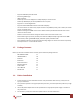
www.avenview.
- 1.5 Supports HDMI Deep Color & Full 3D Re-clocking TMDS single HDCP compliant Allows any source to be displayed on multiple displays at the same time Allows any HDMI display to view any HDMI source at any time Supports 7.
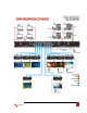
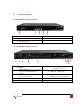
1.7 Panel Description 1.7.1 SW-HDM3D-C5-8X8 Front Panel 1 2 3 4 5 1. Power: Power Control 2. 7 Segment LED Indicators 3. Front Panel Push Buttons 4. IR Sensor 5. Ext. IR: IR Receiver 1.7.2 SW-HDM3D-C5-8X8 Rear Panel 1 2 3 4 5 1. RS232 3. IR Pass Through 1 – 8: 3.5mm IR blaster socket for individual HDMI Source Control Output Ports: 8 RJ-45 TMDS/DDC outputs for each output channel 5. 7. SW Main: DIP Switches 9. USB: 6789 2. SW 1-8: DIP Switches (See Dip switch Section) 4.
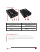
1.7.3 HDM3D-C5SW-R 1. IR Receiver: Plug in IR receiver 3. HDMI Signal Input: Plug in CAT 5/6 5. IN Put Channel: Displays the current HDMI Source Signal Level 0 – 7: Adjust the 8-level equalization control to the received HDMI signals. 7. 2. 5V DC Power jack 4. IR signal: Plug in the CAT5/6 connected from the respective IR signal port on the SW-HDM3D-C5-8X8. Input Select: Push button for switch Input source channel in sequential order 6. 8.
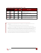
1.7.3 Dip Switch for EDID & Audio Settings (SW1 – SW8) DIP Switch Position PIN # 1 PIN # 2 Video Audio Description 1 OFF OFF 1080p Surround OFF ON 720p/1080i Stereo ON OFF Bypass Bypass ON ON Bypass 4 Stereo 2 4 Default Mode : EDID up to 1080p & Surround sound Audio Output up to 7.1Ch (DTS-HD Master & Dolby TrueHD) 2 Safe Mode : Forces system to output at 720p/1080i with Stereo Audio.
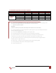
1.7.4 SW Main Dip Switch for Firmware Update DIP Switch Position PIN # 1 OFF Normal Operation Mode6 RS232 OFF Normal Operation Mode USB ON Firmware Block A [main] Update ON Block B [remote] Mode7 ON Block C [HDMI] PIN # 2 PIN # 3 PIN # 4 OFF OFF OFF OFF OFF ON OFF OFF OFF OFF ON OFF ON OFF OFF 6 Factory default for SW Main is pin#1-OFF [], pin#2-OFF [], pin#3-OFF [], & pin#4-OFF [].
1.8 IR Control Patch IR Blaster Cable IR Receiver Cable Incorrect placement of IR Blaster and Receiver may result in the failure of the IR extenders. Please check carefully before plugging in the IR extender to the respective IR sockets. Warranty will not cover the damage. www.avenview.
1.8.1 Supported IR Data Formats Data Format NEC RC5 TOSHIBA MICOM CODE GRUNDIG CODE SONY 12 BIT CODE SONY 15 BIT CODE SONY 20 BIT CODE RCA CODE RCM CODE MATSHUSHITA CODE MITSUBISHI CODE ZENITH CODE JVC CODE M50560-001P MN6125H MN6125L MN6014-C5D7 MN6014-C6D6 MC14457P LC7464(AHEA) GEMINI-CM Suitable Not Recommended www.avenview.
1.9 Installation (SW-HDM3D-C5-8X8) To setup Avenview SW-HDM3D-C5-8X8 follow these steps for connecting to a device: Matrix Switch 1. 2. 3. 4. 5. 6. 7.
1.10 Operation and IR Control 1.10.1 Source Side 1.10.1.1Method A: Push Button 1. Use the “” or “—“ channel button on output port to select which port to be changed. “”: change selected output port in ascending order “—“: change selected output port in descending order 2. Push the “” or “—“ channel button on Input channel to select the HDMI input source you want to display on this selected output port in step 1 in sequential order.
1.10.2 Display Side 1.10.2.1Method A: Push Button Press the INPUT SELECT push button to switch the input source on the respective output port connected to the matrix receiver in sequential order. The selected input source will be displayed on the LED of INPUT CHANNEL. 1.10.2.2Method B: IR Remote Control for Switching Input Channels Please decide which input channel to be selected by pressing Source Selection 1 to Source Selection 8.
1.11 RS232 Serial Port Control Scan: Press Scan button, the machine will scan the all com port and show them. Select the RS232 serial port connected to the machine. And set device ID 255 is for all device. Only the same device id or 255 can get the command you sent. Press OK. Get the new status from the machine you select. www.avenview.
Setting: Press Get button to read back device ID. Press Set button to write device ID. Linkage: Press Linkage button to read back all status Open / Close: Press this button to Close or Open COM Port. Mapping Button: Select All Output: Select “set all output”, and then select the source on main menu. You can quickly set all output to the same source. Unselect All Output: Release output selection. Select Input1~8-Output: Select Input Source. Then select the output port icon.
Fast Select Button: Press Fast select button. Quick setting. Input one Output Port one Input two Output Port two ….. Press Fast select pull down menu. Select Input Num-Output Num Input source #1 Output port #1 Input source #2 Output port #2 ….. Select Input* - All Output Send the same source to all output. Output Port: Pull down menu and select which source to be sent to this output port. One by one setting On main menu screen. First select input source.
1.11.
Section 2: Specifications Item Units SW-HDM3D-C5-8X8 HDM3D-C5SW-R 8X8 HDMI Matrix Switch over CAT5 HDMI 1.3 Receiver over CAT5 with 3D with 3D Support Support HDMI Deep Color & Full 3D Yes Single Link 225 MHz (6.75Gbps) 480i / 480p / 720p / 1080i / 1080p60 Full HD: (1080p) ~ 35meter (115feet) (CAT5e) / 40meter (130feet) (CAT6) HD: (720p/1080i) ~ 50meter (165feet) (CAT5e) / 55meter (180feet) (CAT6) Surround Sound (up to 7.1 Ch.) or Stereo Digital Audio 8 Level Digital Control 1.
2.1 EDID Learning The EDID learning function is only necessary whenever you encounter any display on the HDMI output port that cannot play audio and video properly. Because the HDMI source devices and displays may have various level of capability in playing audio and video, the general principle is that the source device will output the lowest standards in audio format and video resolutions to be commonly acceptable among all HDMI displays.
2.2 Method 2: Use the Front Panel of The Master Unit Button Output Port Input Channel Function EDID will be read from display via the connected receiver unit from the respective output port The EDID will be sent to the input source connected to respective HDMI input port One by One learning 1. Select the desired Output Port and Input Channel that you want the EDID of the display connected to this specified output port can be learned for the specified input channel. 2.
2.2 IR Discrete Code Default Custom Code - IR2 Code: 00 FF Function 0x17 0x0A 0x0C POWER 0x02 SOURCE SEL. 1 SOURCE SEL. 2 SOURCE SEL. 3 SOURCE SEL. 4 0x54 0x55 0x56 0x01 SOURCE SEL. 5 SOURCE SEL. 6 SOURCE SEL. 7 SOURCE SEL. 8 0x57 0x58 0x59 0x06 INPUT 1 0x18 INPUT 2 0x5B INPUT 3 0x19 INPUT 4 0x07 INPUT 5 0x1B INPUT 6 0x5A INPUT 7 0x1A INPUT 8 0x04 OUTPUT 1 0x0E OUTPUT 2 0x0D OUTPUT 3 0x12 OUTPUT 4 0x05 OUTPUT 5 0x1C OUTPUT 6 0x1D OUTPUT 7 0x1F OUTPUT 8 0x1E www.
Custom Code - IR3 Code: 0x12 0x21 Custom Code: 0x12 0x21 Output 1 Output 2 Output 3 Output 4 Output 5 Output 6 Output 7 Output 8 Source 1 0xA1 0xB1 0xC1 0xD1 0xE1 0xF1 0x11 0x21 Source 2 0xA2 0xB2 0xC2 0xD2 0xE2 0xF2 0x12 0x22 Source 3 0xA3 0xB3 0xC3 0xD3 0xE3 0xF3 0x13 0x23 Source 4 0xA4 0xB4 0xC4 0xD4 0xE4 0xF4 0x14 0x24 Source 5 0xA5 0xB5 0xC5 0xD5 0xE5 0xF5 0x15 0x25 Source 6 0xA6 0xB6 0xC6 0xD6 0xE6 0xF6 0x16 0x26 Source 7 0xA7 0xB7 0xC7
Command Custom Code IR2 0x00 0xFF IR3 0x12 0x21 IR4 0x13 0x31 www.avenview.
Disclaimer While every precaution has been taken in the preparation of this document, Avenview Inc.