AV Connectivity, Distribution And Beyond... VIDEO WALLS VIDEO PROCESSORS VIDEO MATRIX SWITCHES EXTENDERS SPLITTERS WIRELESS CABLES & ACCESSORIES HDMI IP Videowall Matrix Extender with POE IR RS-232 and KVM Function Model #: HDM-C6VWIP-SET © 2013 Avenview Inc. All rights reserved. The contents of this document are provided in connection with Avenview Inc. (“Avenview”) products.
Product Application & Market Sectors Corporate House Of Worship Military Residential Education Industrial Medical Aviation www.avenview.
TABLE OF CONTENTS 1. GETTING STARTED...........................................................................................................................1 1.1 Important Safeguards...............................................................................................................1 1.2 Safety Instructions...................................................................................................................1 1.3 Regulatory Notices Federal Communications Commission (FCC)..........
1. GETTING STARTED SECTION 1: GETTING STARTED 1.1 Important Safeguards Please read all of these instructions carefully before you use the device. Save this manual for future reference. What the warranty does not cover •• Any product, on which the serial number has been defaced, modified or removed.
1.3 Regulatory Notices Federal Communications Commission (FCC) This equipment has been tested and found to comply with Part 15 of the FCC rules. These limits are designed to provide reasonable protection against harmful interference in a residential installation. Any changes or modifications made to this equipment may void the user’s authority to operate this equipment. Warning symbols Description ONLY USE THE PROVIDED POWER CABLE OR POWER ADAPTER SUPPLIED. DO NOT TAMPER WITH THE ELECTRICAL PARTS.
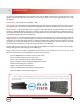
2. Introduction The Avenview HDM-C6VWIP-SET, Matrix IP Extender with Audio, IR RS232 and KVM function provides extension of high definition video and high quality audio. This device can be used into any solution with its unique design allowing connection by the following:Point to Point - (Direct Connection with CAT5/6) - 330ft Point to Multi - Point with CAT5/6 requires a POE Network Switch which supports port based, IGMP v2.0 or above protocol.
2.1 Package Contents Before you start the installation of the HDMI Extender, please check the package contents. 1 HDM-C6VWIP-SET x 1 X1 POWER BRICK (+12V DC 2A) + POWER CORD X1 2 Available on request for International Power USER’S MANUAL 2.2 X1 Before Installation •• Put the product in a level and stable location. If the product falls, it may cause damage or malfunction to components within the casing. •• Do not place the product in temperatures under 0˚C or over 50˚C.
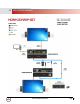
2.3 APPLICATION DIAGRAM www.avenview.
www.avenview.
www.avenview.
2.4 PANEL DESCRIPTION 2.4.1 INPUT PANEL (Transmitter, HDM-C6VWIP-S) Front 1 2 3 1. Operation Mode: Normal Mode: Transmit Rs232 signal between Tx/Rx Debug Mode: Use for Debug device 2. Power LED: Indicates Power active. 3. Link LED: Connection is made to the Rx at the HD Monitor 2.4.2 INPUT PANEL (Transmitter, HDM-C6VWIP-S) Rear 4 5 6 7 8 9 10 4. Power Connector: 12V DC Power Supply 5. USB Port: Type B female USB connection for PC KVM support. 6.
2.4.4 Input Panel (Receiver, HDM-C6VWIP-R) Front 1 2 3 4 5 1. Operation Mode: Normal Mode: Transmit Rs232 signal between Tx/Rx Debug Mode: Use for Debug device 2. Power LED: Indicates Power active. 3. Link LED: Connection is made to the Rx at the HD Monitor 4. USB Port: Type A female USB 2.0 for connecting peripheral devices 5. USB Port: Type A female USB 2.0 for connecting peripheral devices 2.4.5 INPUT PANEL (Receiver, HDM-C6VWIP-R) Rear 6 7 8 9 10 11 12 13 6.
3. Installation (HDM-C6VWIP-SET) To setup Avenview HDM-C6VWIP-SET please follow these steps for connecting to a device: 1. Turn off all devices including monitors / TV 2. Connect a HDMI source (such as a Blu-Ray Disc player or PC) to the Transmitter HDM-C6VWIP-S 3. Connect USB cable to the PC (only if PC is the source and your extending KVM function) 4. Connect IR Blaster to device if applicable to the source IR Eye and 3.5mm male to TX 5.
In this case, select both check boxes in the dialog box and click Allow access to resolve this issue. If the search has timed out or failed, re-perform the search. The Rx and Tx devices are assigned IP addresses in the Auto IP mode by default. The network segment for their IP addresses is 169.254.x.x and the subnet mask is 255.255.0.0.
SEARCHING DEVICES STEP 1: Click search as shown below in DEVICE LIST SECTION STEP 2: All functions are disabled when in search is in progress STEP 3 When search is completed the discovered devices are displayed in the device list window.The devices will show active “Green Circles”. Note: If the Rx and Tx devices have been configured before by this software tool, Check the Restore matrix after search box.
4. SETTING DEVICE PARAMETERs To change or set the device parameters right-click on any device as shown below; OPERATION DESCRIPTION Config User can configure the device parameters. Such as device name and IP preference(AUTO DHCP STATIC). Update Update any changes made with-in the Config. Delete Deletes the devices that have been searched and is listed below in the devices column. Turn On OSD Displays ON Screen Display- Info This operation is valid only when a single device is selected.
MODIFY DEVICE SETTINGS When you right- click a device in the Device List and choose Modify the device setting dialog box is displayed. www.avenview.
5. DEVICE SETTING WINDOW GUIDE GUI ELEMENT ATTRIBUTE DESCRIPTION Devices Indicates the current device on which you perform operations. Host Name ID Indicates the host name ID, which is generated by the system and cannot be changed. Name PARAMETER Indicates the user-defined device name that contains a maximum of 80 characters. IP Address Indicates the device IP address, which can be set only when the static mode is selected.
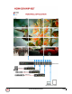
6. MATRIX SETTINGS In the main GUI of the HDMI over IP tool, the Matrix area displays all the GUI elements related to device connections. GUI ELEMENT ATTRIBUTE DESCRIPTION Creates a New Configuration Modifies the current Configuration. BUTTON Deletes the current Configuration. Applies the Configuration connection settings to the connected devices. OPTION Specifies that settings are applied immediately after you double-click the intersection between a row and column in the lower part.
CREATE SCENE WINDOW After your click in the SCENE area, the Create dialog box is displayed The user can change the configuration layout. Modify Scene – The user can edit the Name or Change the Layout SCENE AREA WINDOW You can also right click to perform other operations in the Scene dialog box. www.avenview.
OPERATION DESCRIPTION Change TX User can select which TX (source to be displayed) from the search devices on each Monitor- Matrix /Videowall Function Change RX User can select which RX (Monitor) to be configured Matrix/Videowall Function Remove TX Deletes the TX source from the search devices below in the devices column. Remove RX Deletes the RX Monitor from the search devices below in the devices column. Select All This selects all the Cells in the Scene window dialog box.
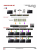
7. VIDEOWALL SETUP The user can Right-Click in the scene area to open the user configurable options: STEP 1: Choose Select All STEP 2: When all the cells are selected right click and choose Combine After the second step is completed Videowall Properties window pops up www.avenview.
STEP 3: Create a Name for the Videowall STEP4: Insert the measurements of the Display Bezel Width and Height NOTE: (All Monitors Must be the Same) OW – Outside width of Monitor/TV in mm OH – Outside height of Monitor/TV in mm VW- Inside width of Monitor/TV in mm VH- Inside width of Monitor/TV in mm STEP 4: Choose which source configuration you would like to setup Single Host Mode: Assign the same video-source to all cells.
STEP 5: The user can identify the Videowall is created in the Control Software by the double green lines combining all the TVs the user have created in the SCENE settings Example 3x3 STEP 6: The user can easily right click on the Videowall created and choose Change TX, this will allow simple switching of any of the searched TX in the listed devices to be displayed across the Videowall. www.avenview.
8. IR REMOTE CONTROL These units have an IR library built in the Control software which allows the user to easily send IR commands form your PC/ Laptop. www.avenview.
8. RS232 REMOTE CONTROL These units have a RS-232 library built in the Control software which allows the user to easily send RS-232 commands form your PC/Laptop. www.avenview.
9. CONFIGURATION FILE MANAGEMENT Default file: when the configuration tool is closed, the Windows OS would save the configuration file default.hoi to the working directory of current user: Windows XP by C:\Documents and Settings\#user#\Local Settings\Application Data\ControlPro; Windows Vista or later OS version by C:\Users\#user#\AppData\Local\ControlPro, #user# is current user name of operation system). When start the tool next time, it would automatically read the configuration file default.hoi.
10. LOGS The logs have recorded the tool operation and device communication information. They can be used by technical engineers for troubleshooting. www.avenview.
SECTION 11: SPECIFICATIONS 11. Specifications Item Description UNITS HDM-C6VWIP-S HDM-C6VWIP-R UNIT DESCRIPTION HDMI Transmitter HDMI Receiver HDCP VIDEO BANDWIDTH Yes with Key Code Single Link 225 MHz (6.75Gbps) SUPPORTED RESOLUTIONS DTV/HDTV; 1080P/1080i/720P/576P/480P/576i/480i RESOLUTION AND DISTANCE @ 8-bit Full HD: (1080p) ~ 100meter (330feet) (CAT5/6/7) AUDIO SUPPORT IR/RS232 SUPPORT Stereo and Digital Audio Pass Through ONLY within Control Software INPUT TMDS SIGNAL 0.5-1.
1. All HDMI over CATx transmission distances are measured using Belden CAT6A (625MHz), 4-Pair,UTP-Unshielded, Riser-CMR, Premise Horizontal Cable, 23 AWG Solid Bare Copper Conductors, Polyolefin Insulation, Patented Double-H spline, Ripcord, PVC Jacket using Quantum 980 signal HDMI Video Generator Module with Video Pattern Testing and shielded ends. 2. The transmission length is largely affected by the type of category cables, also the type of HDMI sources, and the type of HDMI display.
Avenview Warranty Certificate AVENVIEW CORP. (“Avenview”) warrants Avenview-branded product(s) contained in the original packaging against defects in materials and workmanship when used normally in accordance with Avenview's enclosed manual guidelines for a period of THREE (3) YEARS from the date of original retail purchase - Warranty Period. Avenview’s published guidelines include but are not limited to information contained in technical specifications, user manuals and service communications.
AV Connectivity, Distribution And Beyond... TECHNICAL SUPPORT USA Head Office Office Avenview Corp. 275 Woodward Avenue Kenmore, NY 14217 Phone: +1.716.218.4100 ext223 Fax: +1.866.387-8764 Email: info@avenview.com Canada Sales Avenview 151 Esna Park Drive, Unit 11 & 12 Markham, Ontario, L3R 3B1 Phone: 1.905.907.0525 Fax: 1.866.387.8764 Email: info@avenview.com Avenview Europe Avenview Europe Demkaweg 11 3555 HW Utrecht Netherlands Phone: +31 (0)85 2100- 613 Email: info@avenview.