
Specifications


www.avenview.com
Page 8
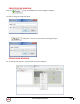
2.4 PANEL DESCRIPTION
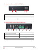
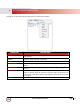
2.4.1 INPUT PANEL (Transmitter, HDM-C6VWIP-S) Front
1. Operation Mode: Normal Mode: Transmit Rs232 signal between Tx/Rx Debug Mode: Use for Debug device
2. Power LED: Indicates Power active.
3. Link LED: Connection is made to the Rx at the HD Monitor
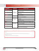
2.4.2 INPUT PANEL (Transmitter, HDM-C6VWIP-S) Rear
4. Power Connector: 12V DC Power Supply
5. USB Port: Type B female USB connection for PC
KVM support.
6. Ethernet Jack: HDMI signal and control data out to
RX
7. HDMI IN: HDMI Female 19 Pin port for source
device
8. HDMI OUT: HDMI Female 19 Pin port for local out
HDMI Monitor
9. RS-232 Jack : 3 pin Terminal Block Connector for
serial control
10. IR Connector: 3.5mm IR Blaster IN
1 2 3
4 5 6 7 8 9 10