RKVM Series User’s Guide Models RKVM-N17, RKVM-N19 Series - With KVM options Models RKVM-17-SD, RKVM-19-SD Series - Short depth version - Without KVM options © 2007 Avenview Inc. All rights reserved. The contents of this document are provided in connection with Avenview Inc. (“Avenview”) products.
Table of Contents Section 1 – Getting Started .................................................................................................................... 4 1.1 Important Safegaurds ............................................................................................................ 4 1.2 Safety Instructions ................................................................................................................. 5 1.3 Regulatory Notices Federal Communications Commission (FCC) ...
4.1 KVM Options ........................................................................................................................ 21 4.2 DVI-D Option ........................................................................................................................ 21 4.3 S-Video + RCA Input Option ................................................................................................. 21 4.4 S-Video + BNC Input Option .............................................................
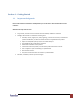
Section 1 – Getting Started 1.1 Important Safegaurds Please read all of these instructions carefully before you use the device. Save this manual for future reference. What the warranty does not cover Any product, on which the serial number has been defaced, modified or removed. Damage, deterioration or malfunction resulting from: Accident, misuse, neglect, fire, water, lightning, or other acts of nature, unauthorized product modification, or failure to follow instructions supplied with the product.
1.2 1.3 Safety Instructions Unplug equipment before cleaning. Don’t use liquid or spray detergent; use a moist cloth. Keep equipment away from excessive humidity and heat. Preferably, keep it in an air-conditioned environment with temperatures not exceeding 40° C (104° F). When installing, place the equipment on a sturdy, level surface to prevent it from accidentally falling and causing damage to other equipment or injury to persons nearby.
1.
1.5 1.6 Before Installation It is very important to locate the LCD Rackmount Keyboard Drawer in a suitable environment. The surface for placing and fixing the LCD Rackmount Keyboard Drawer should be stable and level or mounted into a suitable cabinet. Make sure the place has good ventilation, is out of direct sunlight, away from sources of excessive dust, dirt, heat, water, moisture and vibration. Position LCD Keyboard Drawer with respect to related facilities.
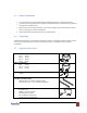
1.8 Peripheral Products Item Description DB-15 KVM Cat5 KVM KVM Extender 1.
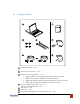
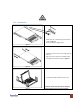
1.10 Installation Install each rear L-bracket using two fasteners shown in Figure 1. Leave the fasteners slightly loose Figure 1 Measure the front and rear mounting depth of the rack. Align each rear L-bracket to a suitable length and tighten the fasteners shown in Figure 2. Figure 2 Figure 3 Fix the LCD keyboard drawer into the rack. * Hardware (screws and cage nuts) for fixing the mounting bracket to the rack is not provided. www.avenview.
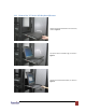
1.11 How to Use “N” Series LCD Keyboard Drawer Gently pull the tab toward the front of the LCD, shown in Figure 4 Figure 4 Flip up the LCD to a suitable angle, as shown in Figure 5 Figure 5 Operate the LCD keyboard drawer, as shown in Figure 6 Figure 6 www.avenview.
1.12 How to Use the Slides A white arrow release button is located on the outside of each slide, as shown in Figure 7 Figure 7 Push the white arrow button on either side of the LCD keyboard drawer to unlock, as shown in Figure 8. Avoid pressing the red button located on either side Figure 8 Hold down the white arrow button until the LCD keyboard drawer is located in the rack, as shown in Figure 9 Figure 9 www.avenview.
1.13 How to Install “One Man” Installation Slides 1.13.1. Package Contents 1 Mounting bracket x 2 pcs 2 Front mounting ear (left & right ) x 2 pcs 3 Support bracket x 4 pcs 4 M6 cage nut x 8 pcs 5 M6 washer x 8 pcs 6 M6*15mm screw x 8 pcs 7 M3.2*4.5mm screw x 14 pcs 1.13.2. Install the Front Mounting Ear x 2 pcs Disassemble the standard front mounting ears carefully Install the optional front mounting ears with M3.2*4.5mm screw x 8pcs www.avenview.
1.13.3. Install into Rack Attach the mounting brackets to vertical mounting rails. Leaving the screws slightly loose. Attach left and right front mounting ears to vertical rails. Tighten the screws. Attach the support brackets to chasis with M3.2*4.5mm screws x 6 pcs Installation complete. Model No. NBK-01 Pickup the unit. Insert inner members of slides into the already mounted internal slide members in the rack. www.avenview.
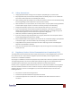
1.14 Connect to Server via USB Interface Figure 10: Example of connecting CD-6 2-in-1 USB KVM cable to server via USB Interface 1.15 Connect to KVM via USB Interface Figure 11: Example of connecting CD-6 2-in-1 USB KVM cable to KVM via USB Interface RKVM-N17-SD, RKVM-N19-SD Series are external power versions. The above connection is only for the LCD keyboard without KVM switch built-in For the LCD keyboard drawer with KVM switch built-in, please refer to KVM switch user manual. www.avenview.
1.16 Connect to Server via PS/2 Interface Figure 6: Example of connecting CD-6 3-in-1 PS/2 KVM cable to server via PS/2 Interface 1.17 Connect to KVM via PS/2 Interface Figure 7: Example of connecting CD-6 3-in-1 PS/2 KVM cable to KVM via PS/2 Interface RKVM-N17-SD, RKVM-N19-SD Series are external power versions. The above connection is only for the LCD keyboard without KVM switch built-in For the LCD keyboard drawer with KVM switch built-in, please refer to KVM switch user manual. www.avenview.
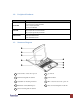
Section 2: Operations 2.1 On-screen Display Operation 17" & 19” LCD membrane Membrane Switch Function Power light Green = On Orange = Power saving Power on / off LCD Display the OSD menu Scrolls through menu options and adjusts the displayed control Exit the OSD screen Shortcut key to auto adjustment by pressing the button for 5 seconds or Toggle analog, digital & video connection (DVI-D and video options only) www.avenview.
2.2 On-screen Menu BRIGHTNESS / CONTRAST Brightness Adjust background black level of the screen image. Contrast Adjust the difference between the image background (black level) and the foreground (white level) AUTO ADJUST Auto Adjust Fine tunes the video signal to eliminate waviness and distortion. A “Adjusting” message is displayed during the process Auto Tune Optimize phase, clock, position and size.
Image Brightness Contrast 1 Sharpness Adjust the image from weak to sharp Saturation Adjust the saturation of the image color Hue Geometry Adjust the screen hue value H. Position V. Position Adjust automatically sizes, centers, and fine tunes the video signal to eliminate waviness and distortion. An “Adjusting” message is displayed during the process.
Section 3: Specifications Item Description Form Factor 1U rack mounting on slide-out rails LCD Manufacturer Diagonal Size Max. Resolution Brightness (cd/m²) Color Support 17" TFT 19" TFT 1280 x 1024 1280 x 1024 300 300 16.2 Mil. 16.7 Mil. Contrast Ratio (typ.) 700:1 1000:1 Viewing Angle (H/V) 150˚ x 135˚ 150˚ x 135˚ 337 x 270 376 x 301 2 1.3 Display Area (mm) Tr Response Time (ms) VGA Signal Input Analog RGB, 0.7Vp-p Sync.
3.1. Keyboard & Mouse Supporting layouts N keyboard integrated with N keyboard integrated with Trackball touchpad www.avenview.
Section 4: Optional Specifications 4.1 KVM Options Our KVM is designed to seamlessly integrate into the rear of our full range of LCD drawer solutions: For KVM operation, please refer to "Integrated LCD KVM Switch" user manual Option with high density Cat5 KVM with either 16 or 32 ports Option with cost efficient DB-15 KVM integration with either 8 or 16 ports Please ask your supplier for full KVM details 4.
4.4 S-Video + BNC Input Option Internal power version S-Video BNC 3-in-1 VGA KB mouse console port External power version Remarks: Package includes an extra 6ft S-Video cable 4.5 DC Power Option Model 12V 24V Input Rating Input Voltage 12 Volt 24 Volt Input Rage 9 ~ 18V 18 ~ 36V Input Current -No Load 50 mA 50 mA -Full Load 4950 mA 2450 mA Output Rating Output Voltage 12 Volt 12 Volt Output Current 4.16A 4.16A Efficiency 84% 85% Package does not include power cord and AC power adapter www.
Section 5: Troubleshooting How do I adjust the resolution? To change monitor resolution in Windows, click Start -> Control Panel -> Display. Select Settings tab to adjust the monitor resolution in Desktop Area. The available resolutions, “640x480”, “800x600”, “1024x768”, “1152x864”, 1280x1024”, are determined by the display card in your computer. Is interface signal appeared on LCD normal when shutting down the computer? In rare cases, interface may appear on the monitor.
Section 6: Dimensions Model RKVM-N17 RKVM-N19 RKVM-N17-SD RKVM-N19-SD Product Dimension (W x D x H) Package Dimension (W x D x H) Net Weight Gross Weight 442 x 650 x 44 mm 17.4 x 25.6 x 1.73 in 442 x 600 x 44 mm 17.4 x 25.6 x 1.73 in 442 x 480 x 44 mm 17.4 x 18.9 x 1.73 in 442 x 480 x 44 mm 17.4 x 18.9 x 1.73 in 589 x 856 x 168 mm 22.2 x 33.7 x 6.8 in 589 x 856 x 168 mm 22.2 x 33.7 x 6.8 in 581 x 705 x 175 mm 22.9 x 27.8 x 6.9 in 581 x 705 x 175 mm 22.9 x 27.8 x 6.
Disclaimer While every precaution has been taken in the preparation of this document, Avenview Inc.