
User`s guide


www.avenview.com
8
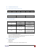
3.2 Communication Protocol
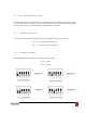
3.2.1 Request Signal from Host to Matrix Switch
Head
Address
Output 1
Output 2
Output 3
Tail
1 byte
2 byte
1 byte
1 byte
1byte
1 byte
3.2.2 Reply Signal from Matrix Switch to Host
Head
Address
Tail
1 byte
2 byte
1 byte
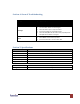
3.2.3 Data of Each Signal
Name
(HEX)
Note
HEAD
0x21(‘!’)
Request: Request from main
computer
0x24(‘$’)
Reply: Reply from SW-DVI-4X2
ID1
0x30 ~ 0x39
2 Byte HEX ASCII
ID2
Ox30 ~ 0x39
OUT1
0x31 ~ 0x34
Output 1 Select
0: Current Output Port OFF
1 ~ 4: Connect each Channel
with Output No.1 Channel
OUT2
0x31 ~ 0x34
Output 2 Select
0: Current Output Port OFF
1 ~ 4: Connect Each Channel
with Output No. 1 Channel
TAIL
0x2A(*)
Frame End Mast
e.g. 1: In case of digital switcher address 3,
Output Port 1 →Input Port #4, Output #2 →Input Port #3, Output Port #3 →Input Port #6,
Request Frame: 0x21, 0x30, 0x33, 0x34, 0x33, 0x36, 0x2a
Replay Frame: 0x24, 0x30, 0x33, 0x2a
3.2.4 Communication Protocol
- Baud Rate: 9600bps
- Data Bit: 8 bit
- Stop Bit: none
For RS485 communication, please use RS232 to RS485 converter