AVerMedia® AVerDiGi EB1304 NET Operation Manual www.avermedia.com www.averdigi.
FCC NOTICE (Class B) This device complies with Part 15 of the FCC Rules. Operation is subject to the following two conditions: (1) this device may not cause harmful interference, and (2) this device must accept any interference received, including interference that may cause undesired operation. Federal Communications Commission Statement NOTE- This equipment has been tested and found to comply with the limits for a Class B digital device, pursuant to Part 15 of the FCC Rules.
- WARNING TO REDUCE RISK OF FIRE OR ELECTRIC SHOCK, DO NOT EXPOSE THIS APPLIANCE TO RAIN OR MOISTURE CAUTION IF THERE IS ANY DAMAGE, SHORTAGE OR INAPPROPRIATE ITEM IN THE PACKAGE, PLEASE CONTACT WITH YOUR LOCAL DEALER.
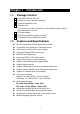
Table of Contents Chapter 1 Introduction .......................................................................1 1.1 Package Content........................................................................................ 1 1.2 Features and Specifications ....................................................................... 1 1.3 Front Panel ................................................................................................ 2 1.4 Back Panel.....................................................
8.2.1 To Setup Remote Console Setting....................................................... 44 8.3 Using the Remote Playback ..................................................................... 45 8.3.1 Familiarizing the Local Playback Buttons ............................................ 46 8.3.2 Familiarizing the Download and Playback Buttons .............................. 48 Appendix A Registering Domain Names ..........................................................
Chapter 1 1.1 Introduction Package Content (1) AVerDiGi EB1304 NET unit (2) Remote Control (batteries included) (3) Quick Installation Guide (4) Power Cord * The power cord varies depending on the standard power outlet of the country where it is sold. (5) Power Adapter (6) DVR accessories (including 4 screws) (7) Software CD (User Manual included) 1.
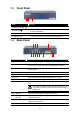
1.3 Front Panel (1)(2) (3) (4) Name Function (1) DVR Power LED : Light when the unit is power on (2) HDD LED : Indicate the hard disk running state. Light when the HDD is running (Read/Write) (3) IR Sensor : Receive signal from the remote control to operate the unit (4) USB 2.0 Port : Connect to pen drive / external hard disk for backup 1.
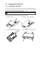
1.5 Setting Up the DVR Unit 1.5.1 Installing the Hard Disk The DVR unit allows user to install one hard disk. Before installing the hard disk, make sure to set the hard disk master jumper setting. Adjust the jumper setting according to the instructions on the hard disk label. i Use 40GB/ 7200RPM IDE interface hard disk or larger is recommended Follow the illustrated instructions below to install the hard disk: 1. Loosen all screws 2. Push the cover backward and lift 3.
5. Connect the end of the IDE cable 6. Secure the hard disk inside the unit and the power connector to the hard then replace unit cover disk 7. Push the cover forward 8. Secure the cover 9. You may now connect all the cables.
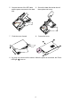
1.5.2 Connecting Devices The back panel of the DVR unit, user can connect up to 4 video cameras, 4 sensor devices, 1 alarm device and output video to a TV or CRT/LCD monitor. Connecting the unit to a pen drive or external hard disk through USB connection for backup, then use the bundled software enables user to transfer, playback and segment the video.Follow the illustration below to make the connection: Each time user changes the video display output, the power must be UNPLUGGED and PLUGGED to reset 1.5.
1.5.3.1 I/O Card Sensor and Relay pinhole allocation: The signal from the sensor (i.e., infrared sensors, smoke detectors, proximity sensors, door sensors, etc.) is being transmitted to the unit and this triggers the system to respond and send signal to relay device (i.e., alarm, telephone etc).
Chapter 2 2.1 Operating the EB1304 NET Familiarizing the Remote Control Buttons Use the Remote control to operate the OSD menu on surveillance screen.
Function ( 11) Decrease the video playback at the speed of 2x, 4x 8x or 16x ▼ ▼ Button Fast play the video playback at the speed of 2x, 4x 8x or 16x ▼ ▼ (12) Stop playing / Stop recording (14) USB backup(see 2.1.
2.1.2 Using USB Backup Button User can press button to backup the AB Repeat video file. 1. Set the AB Repeat file (see 2.1.1). 2. Plug in pen drive or external hard disk to DVR USB BAKCUP system. YES(SELECT) / NO(MENU) 3. During the AB Repeat playback, press button. 4. And then, press press (NO) to exit backup mode. i 2.2 (YES) to start backup file or The DVR system doesn’t support the power for external hard disk. Therefore, the external hard disk need has power supply by itself.
2.3 Surveillance Screen To know if the channel is being recorded, the “ ” record symbol would appear beside the channel number. The (microphone) and (speaker) indicate that the audio is available. The information below the screen shows the current date and time, recording mode (record schedule setting), and the percentage of the used hard disk space.
TIME SEARCH (search by date and time): Use the and ▲ buttons and select ▼ SEARCH TIME. Then press or ▼ 1. TIME SEARCH HARD DISK : START TIME : 2006 / 05 / 04 END TIME : 2006 / 05 / 05 10 : 00 : 01 13 : 08 : 13 SEARCH TIME : 2006 / 05 / 04 10 : 00 : 01 again to make the selection. 2. In the SEARCH TIME, user may now select the date and time from where you want to begin the video playback. buttons to move the selection to the left and right. Use the buttons to select the date and time.
Chapter 3 OSD Navigation Tree The follow figure is an OSD menu tree map. To call out the OSD menu, press on the remote control.
3.1 Menu Function If the unit is currently recording the video, user may have to stop video recording to change the settings. Use remote control to navigate in the OSD menu. The red frame turns yellow when you are making a selection.
Description RECORD SCHEDULE 00 : 00 - 01 : 00 ALWAYS REC 01 : 00 - 02 : 00 ALWAYS REC 02 : 00 - 03 : 00 ALWAYS REC 03 : 00 - 04 : 00 ALWAYS REC 04 : 00 - 05 : 00 ALWAYS REC 05 : 00 - 06 : 00 ALWAYS REC 06 : 00 - 07 : 00 ALWAYS REC 07 : 00 - 08 : 00 ALWAYS REC 08 : 00 - 09 : 00 ALWAYS REC 09 : 00 - 10 : 00 ALWAYS REC 10 : 00 - 11 : 00 ALWAYS REC 11 : 00 - 12 : 00 ALWAYS REC 12 : 00 - 13 : 00 ALWAYS REC SUBMENU PASSWORD CHANGE VIDEO ADJUSTMENT DATE TIME AUTO RECORD AUTO SCAN PASSWORD SETUP AUDIO RECORD AUDI
OSD MENU Description SET NW PASSWORD CURRENT NEW CONFIRM SUBMENU PASSWORD CHANGE VIDEO ADJUSTMENT DATE TIME AUTO RECORD AUTO SCAN PASSWORD SETUP AUDIO RECORD AUDIO MUTE VIDEO SYSTEM MUTIPLE REMOTE REMOTE ID VIDEO ADJUSTMENT : 2006 / 04 / 20 17 : 54 : 50 ON ON NO ON OFF NTSC OFF 1 Select the camera number and set to adjust the video brightness, contrast, hue, and saturation value VIDEO ADJUSTMENT CAMERA BRIGHTNESS CONTRAST HUE SATURATION COLOR PHASE RESET TO DEFAULT VALUE 1 050 050 000 024 MODE 1 NO DA
OSD MENU Description AUDIO RECORD : Enable/disable audio recording. To record sound, make sure the audio input device(ex: microphone) is connected to the unit AUDIO MUTE : Enable/disable to hear audio sound. To hear sound, make sure the unit is connected to an audio output device (ex: speaker). If user recorded video in audio mute status, there is no sound when playback The audio input and output device must be powered by external power. The DVR system doesn’t supply the power to those devices.
OSD MENU HARD DRIVE SETUP OVERWRITE ENABLED YES HDD SIZE 37 GB 78MB HDD USED 0 GB 232MB HDD FORMAT Description OVERWRITE ENABLED : 0% Enable/disable overwriting the earliest record when the hard disk space runs out. By default, the HDD overwrite setting is enabled HDD FORMAT : For security purpose, you may have to enter the password to format hard disk To format hard disk: 1. Use the ▲ and ▼ buttons to go up and or ▼ down and select HDD FORMAT. Then press 2. In the CHECK PASSWORD screen, press .
OSD MENU SENSOR SETUP SENSOR REC TIME ALARM OUT TIME CHANNEL - 1 CHANNEL - 2 CHANNEL - 3 CHANNEL - 4 Description 010 010 NOT NOT NOT NOT SENSOR REC TIME : SEC SEC INSTALLED INSTALLED INSTALLED INSTALLED Set the amount of time (in second) to start record when the sensor has triggered ALARM OUT TIME : Set the amount of time (in second) to continue sending the alarm once triggered CHANNEL 1~4 : Customize the initial state of the attached sensor.
OSD MENU STATIC 1 2 5001 5005 3 4 - - - host addresses. Enter the subnet mask of the IP address which user has assigned to DVR system. GATEWAY: A network device act as a passageway to internet. Enter the network gateway IP address DNS: Domain Name Server translates domain names (such as www.abb.com.tw) to IP addresses. Enter the IP address of DNS if it is available. MAC ADDRESS: Only for user information. Don’t need to enter the MAC address.
STATIC 1 2 5001 5005 3 When DVR system gets an IP address from DHCP server, the information will display as below: 4 NETWORK INFORMATION IP ADDRESS SUB NET GATEWAY DNS MAC ADDRESS 192.168.153.100 255.255.255.255 192.168.153.254 192.168.153.1 00.00.00.00.00.00 PPPOE: Point-to-Point Protocol over Ethernet is a network protocol for encapsulating PPP frames in Ethernet frames. It is used mainly with ADSL services. If your network is using ADSL service connecting to internet, and then, select PPPOE mode.
NETWORK SETUP IP MODE NW ENABLE VIDEO PORT UPGARDE PORT USER SET NW PASSWORD Description STATIC 1 2 5001 5005 1 values and press 3 4 or ▼ OSD MENU to confirm. VIDEO PORT: A port for the remote connection. Any port can be assigned as a video port, except the ports already used by the network services. The default video port is 5001. Use and ▲ ▼ buttons to go up and down and and and ▼ buttons to change the selections values and press ▼ to move to the selection.
OSD MENU Description USB BAKCUP TIME SET 4. START TIME : 2006 / 05 / 04 END TIME : 2006 / 05 / 05 BACKUP CHANNEL BACKUP SIZE BACKUP EXECUTE 1 73GB 2 And then, select BACKUP EXECUTE to start backup video to the USB device. 10 : 00 : 01 13 : 08 : 13 3 89MB 4 80% USER REMAINDER 0GB 5. 820MB When backup is done, press any key to back to main menu. USB BACKUP SUCCESS PRESS ANY KEY TO EXIT 6. To view the backup file, using USB Playback Application(see 4.
Chapter 4 4.1 Using the USB Playback Console Recommended system requirements Pentium®4 2.4GHZ or above Windows®2000/ XP DDR 256 MB Graphic function must support DirectDraw Audio card or built-in Speaker 1 available USB2.0 port 4.2 Installing the USB Playback Console To install the USB Playback Console: 1. Place Installation CD into the CD-ROM drive. When the installation main screen appears, click Install USB Playback Console and then follow the on screen instructions 2.
4.3 Running the USB Playback Console To run the application, click the icon on the PC desktop (1) (2) (3) (4) (5) (6) (7) (8) (9) (10) (11) (17) (12) (13) (16) Name (1) (15) (14) Function Video playback screen To select the video file for playing. The playback application supports *.dvr and *.avf file type. (2) Open File - DVR Recorded File (HD): To playback the recorded video from the hard disk which was recording video on the DVR system. (Also see 4.3.2) - Backup File(.
Name Function Select the event you want to playback. The event list only available when user select to playback in DVR Recorded File(HD). (3) Event List (4) Full screen Use the entire area of the screen to only display the video. To return, press the right button of the mouse or ESC on the keyboard. When you switch to full screen in multiple-screen mode, Left click to toggle to only display one of the video in the multiple-screen mode or all.
Name (17) Sound /Sound bar Function Turn on and off the sound Increase and decrease the volume 4.3.1 To Cut and Save the Portion of the Recorded Video 1. Use the Playback Control buttons or drag the bar on the playback progress bar and pause on where you want to start the cut. Then, click Segment to set the begin mark. 2. Use the Playback Control buttons or drag the bar on the playback progress bar and pause on where you want to end the cut. Then, click Segment to set the end mark.
4.3.3 Playback Backup File(*.dvr) 1. Click Open File button. 2. Select Backup File(*.dvr) and click OK. 3. Locate the backup file folder and click OK. i 4. When open the backup video file, just locate the where backup file folder is. And then, Playback Date/Time Selection window appears. Select the date and time and click OK.
Chapter 5 5.1 Backup Recorded Video File Recommended system requirements Pentium®4 2.4GHZ or above Windows®2000/ XP DDR 256 MB Graphic function must support DirectDraw Audio card or built-in Speaker 1 available USB2.0 port 5.2 Familiarizing with HDD Backup Application (2) (1) (3) (4) (5) (6) (7) (8) (10) Name (9) Function (1) All recorded video events list No.: the list order number Record: the record type(see also Chapter 2.3.
Name Function To select the hard disk drive (4) Source Disk (5) Target Path To locate on where user want to save the file (6) Event (%) Display the backup progress rate of event in percentage (7) Total (%) Display the total backup progress rate in percentage (8) Stop Stop backup progress (9) Start Start backup progress (10) Select All 5.3 1. 2. 3. 4. 5. Select all listed recorded video events. Click the check box again to cancel for selecting all events.
6. 7. 8. Select the hard disk drive and click OK And then, all the recorded video files will list out. Select the event which user wants to backup. Or mark the Select All to select all listed recorded video event 9. Locate on where user wants to save the backup file 10. Click Start to process backup 11. To stop the backup progress, click Stop 12. To play the backup file, see 4.3.3.
Chapter 6 ImageVerification Image Verification is a watermark-checking program to identify the authenticity of a saved image (e.g. by snapshot). This program can only verify uncompressed bmp image files. 6.1 1. 2. 3. 4. To Run the ImageVerification To run the ImageVerification application, click the Watermark button on USB Playback Application main interface. In the ImageVerification screen, click Load Source Image and locate the image source. Click Verify Image to begin the process.
Chapter 7 Video Enhancer The bundled Video Enhancer is a video editing tool and can only be used with *.dvr video file. It allows you to adjust the video picture quality, segment and save the wanted portion of the video, zoom in and out the image, and print or save the screen shot. You can also save the setting and apply it on other files. To run the Video Enhancer application, click the Video Enhancer button on USB Playback Application main interface.
Name Function (9) Default Set the video back to original state and delete all the changes in the history box. (10) History Box List all the actions. (11) Undo Delete the last action. (12) Noise Reduce Adjust the softness and repair the damaged colours. (13) Sharpness Improve the overall image by enhancing edges. This gives the image more depth. (14) Effects Gray Scale: convert the image into black and white (monochrome). Normalize: adjust the brightness intensity.
Chapter 8 Using the Remote Programs User can use Microsoft Internet Explorer to access DVR system by entering the IP address. To use this feature, make sure that you PC and EB 1304 NET both are connected to the internet and the Network feature is enabled. Accessing this feature for the first time you will be prompted by your browser to install WebCamX.cab, allow the installation and you should be able to connect and login afterwards.
8.1 Familiarizing the Web Viewer Buttons Right-clicking on the Web Viewer video screen, enables you to start video recording, change video quality, switch camera and enable/disable DirectDraw. Name Function (1) DirectDraw i Enhance the video quality. Not all graphic cards can support this function. If you can not see the screen display correctly or screen is messed, please check with VGA card vendor. (2) Received file size Indicate the size of the data being sent per second.
Name Function (11) Select cameras to view Select to the view camera from different server. In Select Camera dialog box, Display column, click to enable/disable viewing the camera. Click Add Server and select the server type between DVR and IP Cam to add. Click Delete Server to delete the selected item. Click Import to load the previous saved list. Click Export to save the list. Click Apply All to change all the camera video quality based on the selected setting. Click OK to exit. 8.1.
(3) Video Adjustment Select the camera and adjust the Brightness, Contrast, Hue and Saturation of the selected camera. (4) Default Value Set the video value back to default 8.1.1.2 Record Setup (1) (2) (3) (4) (5) (6) (7) (8) (1) Record Select Enable/disable the channel number to record video i The channels which could be recorded should be enabled in the CAMERA SELECT first. (2) Record Mode Select D1/CIF recording mode. Under D1 mode, the video recording is in full screen resolution.
or LOW. (5) Auto Record Enable/disable auto continue recording when interrupted (i.e., power breakdown, video playback or configuration setup). It continue recording after 10 second of idleness. This is applicable in Always Record mode under schedule setting. (6) Audio Record Enable/disable audio recording. To record sound, make sure the microphone is connected to the unit (7) Disk Overwrite Enable Enable/disable replacing the earliest record when the hard disk space runs out.
- Alarm Out Time Set the amount of time (in second) to continue sending the alarm once activated (2) Sensor Setup - Sensor Status Customize the initial state of the attached sensor for every camera. Refer to the table below to customize the sensor state. Not installed: Indicates that there is no sensor connected Normal open: Indicates that the initial state of the sensor is normal open.
8.1.1.4 Network Setup (1) (2) (3) (1) IP Mode - Static IP Assign a fixed and global IP address for the DVR system IP: Assign a constant IP address which real IP addresses give from ISP. Mask: Enter the subnet mask of the IP address which user has assigned to DVR system. i It is a bitmask used to tell how many bits in an octet(s) identify the subnetwork, and how many bits provide room for host addresses.
Appendix A) - Domain Name Enter the domain name that user wanted. - Auth Key A password use to access DDNS to register the domain name. MAC address of the DVR system is the key for user to register the domain name on AVerMedia DDNS web site. To find MAC address of your DVR system, follow the steps below: 1. In OSD menu, select NETWORK SETUP 2. Select any one of IP mode 3. A NETWORK INFORMATION windows will show up 4.
8.1.1.5 Password Change Click Remote setup button on Web Viewer main interface, and then, click User button to call out the Password Change interface. (1) (2) (1) Superuser Change the remote accessing password of super user. Superuser has the authority to remote setup the DVR system configuration on Web Viewer.
8.2 Familiarizing the Remote Console Buttons (12) (11) (10) (9) (13) (8) (1)(2) Name (3) (4) (5) (6) (7) Function (1) Exit Close the Remote Console. (2) Audio button Enable/disable the sound. (3) Split Screen Mode Select from six (6) different split screen type to playback the recorded video file of all the camera, or one camera over the other or alongside on a single screen. i - If there are only 4 cameras, you won’t be able to switch to 9, 16, and 13 split screen mode.
8.2.1 To Setup Remote Console Setting Click Setup button to call out the System Setting windows. Click OK to exit and save the setting and Cancel to exit without saving the setting. (1) (1) (1) (1) (1) Storage Path Set the directory on where to save the data. When there is not enough free space to record one hour data, the system automatically replaces the oldest data. In case you have more than one storage path, the system automatically saves the data to the next storage path.
8.3 Using the Remote Playback To use this feature, first you need to select the source of the file. Click the Playback button. And then, in the Select Playback Mode dialog box, choose Local Playback to open the file that is recorded in the Remote Console, and Remote Playback to open the file that is recorded in the DVR server. When you choose Remote Playback, select Download and Playback. Click OK to proceed and Cancel to void this operation.
To Make a Selection: 1. Select the date in the calendar. Use and buttons to shift the calendar to the left or right. 2. In the table below, click on the blue block to select and open the recorded file. The blue block turns red when it is selected. The block that appears in white doesn’t have data. You can only select one block when you choose Download and Playback. 3. Click OK to proceed and Cancel to void this operation. 4.
Name Function (3) Hour Buttons The Hour buttons represent the time in 24-hour clock. The blue bar on top of the hour button indicates that there is a recorded video file on that period of time. If there is no recorded data within the hour, there will be no color bar on top of the hour button. While the red bar indicates that you are currently viewing the recorded video file. i (4) Playback Control Buttons (5) Date i Select and click to playback the recorded video file on the specific time frame.
8.3.2 Familiarizing the Download and Playback Buttons (8) (7) (6) (5) (1) Name (3) (2) (4) Function (1) Progress bar Show the progress of the file being played. You may move the bar to seek at any location of the track. (2) Playback Control Buttons Begin: Move at the beginning of the video file. Previous: Go back to the previous frame. Slower: Play the recorded video file at the speed of ½x, ¼x, or ⅛x. Rewind: Wind back the video file. Pause: Briefly stop playing the recorded video file.
Appendix A Registering Domain Names DDNS (Dynamic Domain Name Service) is a data query service mainly used on the Internet for translating domain names into Internet addresses. It allows remote clients to intelligently search dynamic servers without any previous enquiring for servers’ Internet addresses. In order to take advantage of this intelligent service, first register your domain name on the following Web site http://ddns.avers.com.tw 1. User Login Browse the website ddns.avers.com.
Warranty Notice LIMITED WARRANTY AVerMedia TECHNOLOGIES, Inc.