AVerMedia® AVerDiGi EB5416DVD Pro User Manual
FCC NOTICE (Class A) This device complies with Part 15 of the FCC Rules. Operation is subject to the following two conditions: (1) this device may not cause harmful interference, and (2) this device must accept any interference received, including interference that may cause undesired operation. Federal Communications Commission Statement NOTE- This equipment has been tested and found to comply with the limits for a Class A digital device, pursuant to Part 15 of the FCC Rules.
- WARNING TO REDUCE RISK OF FIRE OR ELECTRIC SHOCK, DO NOT EXPOSE THIS APPLIANCE TO RAIN OR MOISTURE CAUTION IF THERE IS ANY DAMAGE, SHORTAGE OR INAPPROPRIATE ITEM IN THE PACKAGE, PLEASE CONTACT WITH YOUR LOCAL DEALER. WARRANTY VOID FOR ANY UNAUTHORIZED PRODUCT MODIFICATION NOTICE - INFORMATION IN THIS DOCUMENT IS SUBJECT TO CHANGE WITHOUT NOTICE. - THE INFORMATION CONTAINED HEREIN IS TO BE CONSIDERED FOR REFERENCE ONLY.
Table of Contents Chapter 1 Introduction............................................................................... 1 1.1 Package Content .................................................................................................. 1 1.2 Features and Specifications.................................................................................. 1 1.3 Front Panel ........................................................................................................... 2 1.4 1.5 Back Panel .
.2 Familiarizing with HDD Backup Application ........................................................ 48 5.3 To Backup Recorded Video File.......................................................................... 49 Chapter 6 ImageVerification .................................................................... 51 6.1 To Run the ImageVerification.............................................................................. 51 Chapter 7 iEnhance.........................................................
Chapter 1 1.
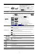
1.3 3 level password authentication mechanism DVD backup (up to 4.2GB) Support 2 HDD backup (up to 1.
Name Function (3) USB 2.0 port 2 x USB 2.0 ports for connecting any USB devices, ex: USB pen drive, external hard disk, keyboard, mouse…and so on. i Do Not plug in two USB storage devices at the same time. (4) Removable Hard Disk Draw i To install hard disk for storage recorded video file For hard disk spec, please referring to http://www.avermedia.com/nvd/hardware-recom_eb_c.
Name Function - (12) Number button - ~ - (13) LCD Display As a number key for entering password in playback and preview mode Channel camera selection number in playback and preview mode As a preset position with in PTZ control mode With button can switch to different screen display modes Display DVR system status such as temperature and operate status A functional key for multiple system control - Press to enable multiple function modes and the button will light up blue.
1.4 Back Panel Name Function (1) Video Loop Out Output the video signal to a CCTV monitor. Only output one channel signal at a time. (2) CH1~ 16 Input the video camera signal and display it on channel 1~ 16 (3) Spot Monitor Output a video signal to a Spot Monitor when an alarm event is coming (4) LAN Port For Ethernet connection (5) TV Out Output the video signal to a TV (6) VGA Out Output the video signal to a CRT or LCD monitor (7) Audio I/O Support 16 channels audio input (ex.
1.5 Setting Up the DVR Unit 1.5.1 Installing the Removable Hard Disk The DVR unit allows user to install one hard disk. Before installing the hard disk, make sure to set the hard disk master jumper setting. Adjust the jumper setting according to the instructions on the hard disk label. i For hard disk spec, please referring to http://www.avermedia.com/nvd/hardware-recom_eb.
5. Carefully insert the hard disk in the removable rack 7. And then, close the removable hard disk drawer 8. cover 9. Lock the removable hard disk drawer keylock 6. Turn the removable hard disk drawer over and screw hard disk with screws Slide the drawer back 10. Power on the removable hard disk drawer 11. You may now connect all the cables.
1.5.2 Install Internal SATA Hard Disk User can install one SATA hard disk inside the DVR unit if it is necessary. Please follow the below steps to install the hard disk. 1. Loosen all screws 2. Push the cover backward and lift 3. Loosen the screws of holder that will make installation more convenient 4. Secure the brackets on the hard disk both side 5. Plug the SATA cable into hard disk 6.
7. Secure the hard disk inside the unit 8. Screw tight the holder 9. Push the cover forward 10.
1.5.3 Connecting Devices The back panel of the DVR unit, user can connect up to 16 video cameras, 16 sensor devices, 4 alarm devices, PTZ camera and output video to a TV or CRT/LCD monitor. Connecting the unit to a pen drive or external hard disk through USB connection for backup, then use the bundled software enables user to transfer, playback and segment the video.
1.5.4 Sensor, Relay and RS485 pinhole allocation The Sensor, Alarm, and PTZ camera ports enable you to connect 16 sensor inputs, 4 relay outputs, and 1 PTZ camera. Just connect the external sensor, relay, and PTZ camera pin directly to the pinhole. Check the table below and locate which pinhole is assigned to sensor input and relay output. 1.5.4.1 Sensor Pin Definition Sensor Pin # 1.5.4.
1.5.4.3 RS485 Pin Definition When connect PTZ camera through RS485 interface, please refer to the following pin definition to connect the DVD and PTZ.
Chapter 2 2.1 Operating the EB5416DVD Pro Familiarizing the Remote Control Buttons Use the Remote control to operate the OSD menu on surveillance screen.
Name (13) Function To save the preset position of PTZ camera. Adjust the PTZ camera lens to the position that user wants, and then press ~ + number button ( ) to save the preset position. (see also Chapter 2.1.3.2) When the PTZ camera in PTZ mode, press preset position number button to move the PTZ camera to preset position.
Name (19) Function To enter the DVR ID number that assigned by user for multiple DVR controlling ( see also Multiple DVR & DVR ID in Chapter 3) ID Press 1 2 3 4 1 ID can unselect all DVR + ~ - Channel camera selection number in playback and preview mode 5 6 7 8 9 10 11 12 13 14 15 16 (20) - As preset positions that work with - With in PTZ control mode button can switch to different screen display modes) 2.1.
i The external hard disk needs to be powered by external power. 2.1.2 Using AB Repeat Function AB Repeat function allow user to set a video segment from A to B point and play on the surveillance screen until user stop. User also can backup AB Repeat file to pen drive or external hard disk (See 2.1.1). (play button) to call out the PLAYBACK menu to find the recorded video that user 1. Press wants to playback. 2. Select TIME SEARCH or EVENT LIST.
2.1.3 Controlling PTZ Camera Using remote control, user can easily control PTZ camera at local site. Before starting, please go to OSD menu to enable PTZ control (see 3.1 Menu Function: PTZ Setup). 2.1.3.1 To Enter the PTZ Mode To control PTZ camera, user need to enter the PTZ mode first. Press channel number button ( 1 ~ button, and camera ) that the selected channel will switch to PTZ mode in a full screen display. To exit PTZ mode, press .
2.1.3.3 To Control PTZ Camera To move, adjust focus, and zoom in/out camera lens can be done by using some function buttons on the remote control. To move the PTZ camera lens to the right To move the PTZ camera lens to the left To move the PTZ camera lens to go up To move the PTZ camera lens to go down To zoom in PTZ camera To zoom out PTZ camera To speed up movement of PTZ camera lens To speed down movement of PTZ camera lens To focus in PTZ camera lens To focus out PTZ camera lens 2.
press or to confirm the selection. 3. To select the format of date, Press or or to change the date format. Press the date. Press or or and buttons to confirm the selection. and 4. After selected the date format, use DATE and press and use to confirm. Use to go up and down and select the and buttons to adjust to confirm the selection. 5. To adjust TIME, follow the above step 3 or 4. 6. Press 2.3 to go back to main menu.
In Playback mode, the (AB Repeat) indicate that playback is in AB repeat status. The indicate that DVR unit is playback recorded video. (Play) Playback Mode The EB5416DVD Pro supports mouse control that user can use mouse (the middle button of mouse) to click channel to switch between preview and playback mode. To switch back, click channel with middle button of mouse again. Click right mouse button on screen to call out the OSD menu.
2.4 Playback the Video The DVR system can record and playback video simultaneously. Therefore, user doesn’t need to stop recording while playback the video. 1. Press 2. Use and buttons to go up and PLAYBACK T IME S E A R C H E V E NT L IS T down and select TIME SEARCH or EVENT LIST. Then, or press to make a selection. TIME SEARCH (search by date and time): 1. and Use buttons and select SEARCH TIME. Then press 2.
2. Use and the list. Press buttons to select from or selection. User again to make the and to go next page or back to previous page.
Chapter 3 OSD Navigation Tree The follow figure is an OSD menu tree map. To call out the OSD menu, press control.
3.1 Menu Function If the unit is currently recording the video, user may have to stop video recording to change the settings. User can use the following way to setup DVR unit. Remote Controller USB Mouse Front Panel control buttons and to go up and down the selection list or For using remote controller, use change the value of selection. Use item. Use or and to move to left and right in the selection list or to make a confirmation. Press to go back previous page or exit from current page.
OSD MENU CAMERA SETUP CAMERA SELECT RECORD SELECT AUDIO RECORD CAMERA TITLE VIDEO SHIELD VIDEO ADJUSTMENT PTZ CONTROL AUTO SCAN AUDIO OUT Description 1 9 1 9 1 9 2 10 2 10 2 10 3 11 3 11 3 11 4 12 4 12 4 12 5 13 5 13 5 13 6 14 6 14 6 14 7 15 7 15 7 15 8 16 8 16 8 16 CAMERA TITLE To assign a name for each channel. The maximum inputs is 12 characters that includes letters of the alphabet, numbers, +, -, @, /, space, dash, and dot.
OSD MENU CAMERA SETUP CAMERA SELECT RECORD SELECT AUDIO RECORD CAMERA TITLE VIDEO SHIELD VIDEO ADJUSTMENT PTZ CONTROL AUTO SCAN AUDIO OUT CAMERA SETUP CAMERA SELECT RECORD SELECT AUDIO RECORD CAMERA TITLE VIDEO SHIELD VIDEO ADJUSTMENT PTZ CONTROL AUTO SCAN AUDIO OUT Description 1 9 1 9 1 9 2 10 2 10 2 10 5 13 5 13 5 13 6 14 6 14 6 14 7 15 7 15 7 15 1 9 2 3 4 5 10 11 12 13 6 14 7 8 15 16 1 9 1 9 1 9 1 9 2 10 2 10 2 10 3 11 3 11 3 11 3 11 3 11 3 11 4 12 4 12 4 12 4 12 4 12 4 12 5 13 5 13 5 1
OSD MENU Description PTZ SETUP CAMERA PTZ CONTROL ID PROTOCOL BAUD RATE AUTO PAN GROUP DWELL TIME BAUD RATE: To setup the baud rate of PTZ camera. For more detail, please refer to your PTZ camera’s user manual. 1 OFF 1 PELCO-D 2400 1-4 5-8 05 SEC 9 - 12 13 - 16 AUTO PAN GROUP: Select the preset number to assign an auto move direction for the PTZ camera. For example: 1-4 means the PTZ camera will auto move from preset position 1, 2, 3 to 4.
OSD MENU MAIN MENU CAMERA RECORD HARD DRIVE SENSOR / ALARM MOTION NETWORK BACKUP SYSTEM Description RECORD To setup the recording relate parameters. RECORD SETUP RECORD MODE RECORD FRAMERATE VIDEO QUALITY RECORD SCHEDULE D1 240 GOOD RECORD MODE Select D1/CIF recording mode. Under D1 mode, the video recording is in full screen resolution and takes turns from one channel to the next one when Auto Scan enables. Each channel is recorded only at a maximum frame rate of 15fps.
OSD MENU RECORD SETUP RECORD MODE RECORD FRAMERATE VIDEO QUALITY RECORD SCHEDULE Description D1 240 GOOD RECORD Use SCHEDULE , , buttons to move to left and right. Use and buttons to select the mode of record schedule. RECORD SCHEDULE SETUP SUN MON TUE WED THU FRI SAT : SENSOR RECORDING : MOTION RECORDING : NO RECORD By default, in 24 hours, the recording schedule is set to always record every hour.
OSD MENU HARD DRIVE SETUP OVERWRITE ENABLED YES HDD1 SIZE 953,669 MB HDD1 USED 1,936 MB HDD1 FORMAT HDD2 SIZE 0 MB HDD2 USED 0 MB HDD2 FORMAT Description HDD 1/2 FORMAT For security purpose, you may have to enter the password to format hard disk To format hard disk: 1. Use and buttons to go up and down and select HDD 1/2 FORMAT. Then press or 2. In the ADMINISTRATOR PASSWORD screen, press . Then use or and buttons to select the security combination number.
OSD MENU Description MAIN MENU CAMERA RECORD HARD DRIVE SENSOR / ALARM MOTION NETWORK BACKUP SYSTEM SENSOR / ALARM To setup sensor and alarm relate parameters.
OSD MENU ALARM SETUP ALARM OUT Description 1 9 1 9 VIDEO LOSS 1 9 HDD FAIL ON COPY SETTING VALUE TO SENSOR MOTION MOTION: BUZZER 2 10 2 10 2 10 3 11 3 11 3 11 4 12 4 12 4 12 BUZZER 5 13 5 13 5 13 6 14 6 14 6 14 7 15 7 15 7 15 8 16 8 16 8 16 Select the channel that will send out the alarm when motion has been detected VIDEO LOSS: Select the channel that will send out the alarm when video is lost. HDD FAIL: Enable/disable send out alarm when hard disk is failed.
OSD MENU MAIN MENU CAMERA RECORD HARD DRIVE SENSOR / ALARM MOTION NETWORK BACKUP SYSTEM Description MOTION SETUP MOTION SETUP SENSITIVITIY MOTION RECORD TIME MOTION CAMERA 1 2 9 10 MASK MOTION L 010 SEC 3 4 5 11 12 13 6 14 7 15 8 16 SENSITIVITY: Set the sensitivity level. The sensitivity is from HI (High), 9~ 2 and LO (Low). MOTION RECORD TIME: Set the amount of time (in second) to record when motion is detected. MOTION CAMERA: Enable/disable the channel number to detect motion.
OSD MENU MAIN MENU CAMERA RECORD HARD DRIVE SENSOR / ALARM MOTION NETWORK BACKUP SYSTEM Description NETWORK SETUP Setup the network parameters for the internet or intranet remote monitor or playback. NETWORK SETUP IP MODE NW ENABLE VIDEO PORT UPGARDE PORT 1 2 3 9 10 11 0080 5005 4 12 5 13 6 14 7 15 8 16 IP MODE The system provides 3 types of IP setup mode – STATIC, DHCP, and PPPOE. IP MODE IP MODE IP ADDR ESS SUB NET GATEWAY DNS MAC ADDR ESS CHANGE STATIC 192 . 168 . 153 . 100 255 . 255 . 255 .
OSD MENU IP MODE IP MODE IP ADDR ESS SUB NET GATEWAY DNS MAC ADDR ESS GET IP Description DHCP 192 . 168 . 153 . 100 255 . 255 . 255 . 255 192 . 168 . 153 . 254 000 . 000 . 000 . 000 00 . 18 . 1A. 02. 00 . 0F - MAC ADDRESS: Only for user information. Don’t need to enter the MAC address. - When all parameters are set, select the CHANGE to confirm the configuration. DHCP: Assign the IP address by local DHCP server to DVR system.
OSD MENU Description NETWORK SETUP IP MODE NW ENABLE VIDEO PORT UPGARDE PORT 1 2 3 9 10 11 0080 5005 4 12 5 13 6 14 7 15 8 16 NW ENABLE: Allow internet remote user to playback or monitor the channels. Without enabling the network function, the channels cannot be playback or monitor from remote site. VIDEO PORT: A port for the remote connection. Any port can be assigned as a video port, except the ports already used by the network services. The default video port is 80.
OSD MENU Description BAKCUP SETTING HARD DISK : HDD 1 START TIME : 2008 / 01 / 04 END TIME : 2001 / 01 / 05 CHANNEL 1 2 3 9 10 11 CALCULATE SIZE BACKUP EXECUTE 4 12 4. 10 : 00 : 01 13 : 08 : 13 5 13 6 14 7 15 And then, select BACKUP EXECUTE and press YES (ENTER) to start backup video BACKUP IN PROCESS 8 16 89MB 15% 820M AVAILABLE SIZE 5. When backup is done, press any key to back to main menu.
OSD MENU SYSTEM SETUP MULTI-QUAD:LIVE MULTI-QUAD:PLAY PASSWORD CHANGE CONFIGURATION TIME SETUP AUTO RECORD AUDIO MUTE MUTLIPLE DVR DVR ID VGA RESOLUTION TEMPERATURE VIDEO SYSTEM OSD TRANSPARENCY LANGUAGE Description OFF OFF OFF 1 1024x768 NTSC LEVEL - 2 ENGLISH AA . 01 . 01 . 00 . 06 DVR ID Assign the ID number for multiple DVR system remote controls. When there are more than one DVR systems, user can enable MULTIPLE DVR function, and then assign DVR ID to each DVR system.
OSD MENU PASSWORD SETUP PASSWORD SETUP ADMINISTARATOR OPERATOR USER Description NO PASSWORD CHANGE Enable/disable full system password protection. This would prevent unauthorized user to stop video recording, change system settings and formatting the hard disk. ADMINISTRATOR: Administrator has the authority of formatting hard disk, changing system settings, remote monitor the DVR system and changes the system settings. The factory default password is 111111.
OSD MENU SYSTEM SETUP MULTI-QUAD:LIVE MULTI-QUAD:PLAY PASSWORD CHANGE CONFIGURATION TIME SETUP AUTO RECORD AUDIO MUTE MUTLIPLE DVR DVR ID VGA RESOLUTION TEMPERATURE VIDEO SYSTEM OSD TRANSPARENCY LANGUAGE Description CONFIGURATION Backup and resort the DVR system setting. OFF OFF OFF 1 1024x768 CONFIGURATION SETUP SAVE CONFIGURATION RESTORE CONFIGURATION NTSC LEVEL - 2 ENGLISH AA . 01 . 01 . 00 . 06 SAVE CONFIGURATION: Backup the current DVR system setting to USB device.
OSD MENU TIME SETUP DATE FORMAT DATE TIME AUTO SYNC TIME TIME ZONE LAST SYNC TIME Description YYYY/MM/DD 2008 / 03 / 12 WED 21 : 07 : 45 OFF GMT 2008 / 01 / 01 00 : 00 : 00 TIME SETUP Setup system date, time, daylight saving, and enable auto synchronize time through network. DATE FORMAT: Select the display format of the date DAYLIGHT SAVING DATE : Set the current date TIME : Set the current time AUTO SYNC TIME: Enable/disable time synchronization automatically through network.
OSD MENU TEMPERATURE SETUP TEMPERATURE FORMAT HIGH THRESHOLD LOW THRESHOLD DVR HOT PROTECT Description C 035 030 055 TEMPERATURE SETUP Set the DVR unit temperature type and high/low threshold limit. TEMPERATURE FORMAT: Temperature pattern display on front LED panel. HIGH THRESHOLD: Set a specific temperature limited (0 ~ 100°C) for fan active. When the hard disk temperature is higher than limited temperature, the fan will be active. The default value is 35°C.
Chapter 4 4.1 Using the USB Playback Console Recommended system requirements Pentium®4 2.4GHZ or above Windows®2000/ XP DDR 256 MB Graphic function must support DirectDraw Audio card or built-in Speaker 1 available USB2.0 port 4.2 Installing the USB Playback Console To install the USB Playback Console: 1. Place Installation CD into the CD-ROM drive. When the installation main screen appears, click Install USB Playback Console and then follow the on screen instructions 2.
4.3 Running the USB Playback Console To run the application, click the icon on the PC desktop (1) (2) (3) (4) (5) (6) (7) (8) (9) (10) (11) (17) (12) (13) (16) Name (1) (14) (15) Function Video playback screen To select the video file for playing. The playback application supports *.dvr and *.avf file. (2) Open File - DVR Recorded File (HD): To playback the recorded video from the hard disk which was recording video on the DVR system. (see also 4.3.2) - Backup File(.
Name Function Select the event you want to playback. The event list only available when user select to playback in DVR Recorded File(HD). (3) Event List (4) Full screen Use the entire area of the screen to only display the video. To return, press the right button of the mouse or ESC on the keyboard. When you switch to full screen in multiple-screen mode, Left click to toggle to only display one of the video in the multiple-screen mode or all.
4.3.1 To Cut and Save the Portion of the Recorded Video 1. Use the Playback Control buttons or drag the bar on the playback progress bar and pause on where you want to start the cut. Then, click Segment to set the begin mark. 2. Use the Playback Control buttons or drag the bar on the playback progress bar and pause on where you want to end the cut. Then, click Segment to set the end mark. To cancel segmentation, click Segment button again. 3. Click Output button to save the wanted portion. 4.
4.3.3 Playback Backup File(*.dvr) 1. 2. 3. Click Open File button. Select Backup File(*.dvr) and click OK. Locate the backup file folder and click OK. i 4. When open the backup video file, just locate the where folder of backup file is. And then, Playback Date/Time Selection window appears. Select the date and time and click OK. 4.3.4 Playback Backup File (*.avf) To playback backup file in *.
Chapter 5 5.1 Backup Recorded Video File Recommended system requirements Pentium®4 2.4GHZ or above Windows®2000/ XP DDR 256 MB Graphic function must support DirectDraw Audio card or built-in Speaker 1 available USB2.0 port 5.2 Familiarizing with HDD Backup Application (2) (1) (3) (4) (5) (6) (7) (8) (12) Name (11) (9) (10) Function No.: the list order number Record: the record type(see also Chapter 2.3.
Name (4) Source Disk To select the hard disk drive (5) Target Path To locate on where user want to save the file (6) Event (%) Display the backup progress rate of event in percentage (7) Total (%) Display the total backup progress rate in percentage (8) Stop Stop backup progress (9) Start Start backup progress (10) Page Switch Pre: go back last page Next: go to next page Page column: enter the page number and click Go button to go to the page (11) Select All Select all listed recorded v
6. Select the hard disk drive and click OK 7. And then, all the recorded video files will list out. 8. Select the event which user wants to backup. Or mark the Select All to select all listed recorded video event 9. Locate on where user wants to save the backup file 10. Click Start to process backup 11. To stop the backup progress, click Stop 12. To play the backup file, see 4.3.3.
Chapter 6 ImageVerification Image Verification is a watermark-checking program to identify the authenticity of a saved image (e.g. by snapshot). This program can only verify uncompressed bmp image files. 6.1 1. To Run the ImageVerification To run the ImageVerification application, click the Watermark button on USB Playback Console main interface. 2. In the ImageVerification screen, click Load Source Image and locate the image source. 3. Click Verify Image to begin the process. 4.
Chapter 7 iEnhance The bundled iEnhance is a video editing tool and can only be used with *.dvr video file. It allows you to adjust the video picture quality, segment and save the selected portion of the video, zoom in and out the image, and print or save the screen shot. You can also save the setting and apply it on other files. To run iEnhance application, click iEnhance button on USB Playback Console interface.
Name Function (12) Noise Reduce Adjust the softness and repair the damaged colours. (13) Sharpness Improve the overall image by enhancing edges. This gives the image more depth. (14) Effects Gray Scale: convert the image into black and white (monochrome). Normalize: adjust the brightness intensity. Equalize: automatically adjust the images that are too dark. De-interlace: smooth out the overlying frames. Static: de-interlace for motionless scene. Dynamic: de-interlace for moving scene.
Chapter 8 Using the Remote Programs User can use Microsoft Internet Explorer to access DVR system by entering the IP address. To use this feature, make sure that you PC and EB5416DVD Pro both are connected to the internet and the Network feature is enabled. Accessing this feature for the first time you will be prompted by your browser to install WebCamX.cab, allow the installation and you should be able to connect and login afterwards.
8.1 Familiarizing the Web Viewer Buttons Right-clicking on the Web Viewer video screen, enables you to start video recording, change video quality, switch camera and enable/disable DirectDraw. Name Function (1) DirectDraw i Enhance the video quality. Not all graphic cards can support this function. If you can not see the screen display correctly or screen is messed, please check with VGA card vendor. (2) Received file size Indicate the size of the data being sent per second.
Name (12) Select cameras to view Function Select to the view camera from different server. In Select Camera dialog box, Display column, click to enable/disable viewing the camera. Click Add Server and select the server type between DVR and IP Cam to add. Click Delete Server to delete the selected item. Click Import to load the previous saved list. Click Export to save the list. Click Apply All to change all the camera video quality based on the selected setting. Click OK to exit.
8.1.1 To Setup Remote System Setting Click OK to exit and save the setting and Cancel to exit without saving the setting. The setting here applies to Remote DVR system only. i - After changed the DVR system setting, refresh your web browser in order to apply the new setting to the DVR system. - 8.1.1.1 Only the superuser has the authority to change remote DVR system settings.
Video Standard NTSC PAL Record Mode - D1 16, 80, 240 16, 80, 200 CIF 16, 80, 160, 240, 480 16, 80, 200, 400 VIDEO QUALITY Select the video quality setting from BEST, HIGH, MEDIUM, GOOD, NORMAL or LOW. BEST – best record quality but less record hours LOW – longest record hour but quality is ordinary NORMAL – allows you to record more hours but the quality of the recorded video is moderate. (2) NTP Setting Setup the time auto synchronization.
- START Setup daylight start up date and time. END Setup daylight stop date and time. TIME OFFSET Assign a time that it is for daylight saving time offset in your time zone. For example: if the time zone is in U.S. Eastern, the time offset is 1 hour. (5) TEMPERATURE Set the DVR unit temperature type and high/low threshold limit. - TEMPERATURE FORMAT: Temperature pattern display on front LED panel. - HIGH THRESHOLD: Set a specific temperature limited (0 ~ 100°C) for fan active.
8.1.1.3 Record Setup (1) (2) (3) (5) (4) (1) Camera icon Select the camera that user wants to set up. (2) Record Select Enable/disable the channel number to record video i The channels which could be recorded should be enabled in the CAMERA SELECT first. (3) Audio Record Enable/disable channel number audio recording. To record sound, make sure the microphone is connected to the unit (4) Record Schedule By default, in 24 hours, the recording schedule is set to always record every hour.
8.1.1.4 Alarm/Sensor Setup (1) (2) (3) (4) (1) Alarm - ALARM OUT Select the way of alarming – BUZZER, RELAY-1, RELAY-2, RELAY-3, RELAY-4, or ALL. - The Condition of Alarm Select the condition that it will trigged the alarm HD Fail Alarm Enable/disable send out alarm when hard disk is failed. Motion Alarm Select the channel that will send out the alarm when motion has been detected Video Loss Alarm Select the channel that will send out the alarm when video is lost.
- Alarm Out Time Set the amount of time (in second) to continue sending the alarm once activated (3) Sensor Setup - Sensor Status Customize the initial state of the attached sensor for every camera. Refer to the table below to customize the sensor state. Not installed: Indicates that there is no sensor connected Normal open: Indicates that the initial state of the sensor is normal open.
8.1.1.5 Network Setup (1) (2) (4) (3) (5) (1) IP Mode Select the IP Mode – Static IP, DHCP, or PPPOE - DHCP Assign the IP address by local DHCP server to DVR system. i The Dynamic Host Configuration Protocol (DHCP) is a set of rules used by a communications device (such as a computer, router or networking adaptor) to allow the device to request and get an Internet address from a server which has a list of addresses available for assignment.
2. Select any one of IP mode 3. A NETWORK INFORMATION windows will show up MAC address of DVR system is display as shown IP MODE IP MODE IP ADDR ESS SUB NET GATEWAY DNS MAC ADDR ESS CHANGE STATIC 192 . 168 . 153 . 100 255 . 255 . 255 . 255 192 . 168 . 153 . 254 000 . 000 . 000 . 000 00 . 18 . 1A. 02. 00 . 0F (4) Static IP Assign a fixed and global IP address for the DVR system - IP: Assign a constant IP address which real IP addresses from ISP.
8.1.1.6 User Setting Click Remote setup button on Web Viewer main interface, and then, click User button to call out the Password Change interface. (1) (2) (3) (1) Superuser Change the remote accessing password of superuser. Superuser has the authority to remote setup the DVR system configuration on Web Viewer. - Password Enter the new password - Password Confirm Re-enter password to confirm (2) Network User The login account for remote connection through the internet.
8.2 Familiarizing the Remote Console Buttons (12) (11) (10) (9) (13) (8) (1)(2) Name (3) (4) (5) (6) (7) Function (1) Exit Close the Remote Console. (2) Audio button Enable/disable the sound. (3) Split Screen Mode Select from six (6) different split screen type to playback the recorded video file of all the camera, or one camera over the other or alongside on a single screen. i If there are only 4 cameras, you won’t be able to switch to 9, 16, and 13 split screen mode.
8.2.1 To Setup Remote Console Setting Click Setup button to call out the System Setting windows. Click OK to exit and save the setting and Cancel to exit without saving the setting. (1) (1) (1) (1) (1) Storage Path Set the directory on where to save the data. When there is not enough free space to record one hour data, the system automatically replaces the oldest data. In case you have more than one storage path, the system automatically saves the data to the next storage path.
8.3 Familiarizing the WebViewer PTZ Buttons (1) (2) (3) (4) (5) Name (1) Direction buttons (2) Zoom +/(3) Select PTZ (4) Focus +/(5) Camera preset position number 8.4 Function Adjust and position the focal point of the PTZ camera. Click the center to pan automatically. Zoom in and out the image. Choose to enable/disable the PTZ camera. In the Select PTZ dialog box, Select column, click to enable/disable viewing and controlling the PTZ camera.
clock. The numbers from 01 to 16 represent the camera number. To Make a Selection: 1. Select the date in the calendar. Use and buttons to shift the calendar to the left or right. 2. In the table below, click on the blue block to select and open the recorded file. The blue block turns red when it is selected. The block that appears in white doesn’t have data. You can only select one block when you choose Download and Playback. 3. Click OK to proceed and Cancel to void this operation. 4.
8.4.1 Familiarizing the Local Playback Buttons (13) (12) (11) (10) (9) (8) (7) (1) (2) (3) (4) (5) (6) Name Function Select from six (6) different split screen type to playback the recorded video (1) Split Screen Mode file of all the camera, or one camera over the other or alongside on a single screen. - If there are only 4 cameras, you won’t be able to switch to 9, 16, and 13 split screen mode. - To zoom in an area on the screen, Right click and Drag a square on the area you want to enlarge.
Name Function in playback mode. (9) Camera ID Show the number of cameras that are being viewed. When you are in single screen mode, click the camera ID number to switch and view other camera. (10) Output Save the segmented file in *.mpg, *.avi, or *.dvr format (see also Chapter 8.3.1.1). (11) Segment Keep a portion of the recorded video you want (see also Chapter 8.3.1.1). (12) Snapshot Capture and save the screen shot either in *.jpg or *.bmp format.
8.4.2 Familiarizing the Download and Playback Buttons (8) (7) (6) (5) (1) (2) Name (3) (4) Function (1) Progress bar Show the progress of the file being played. You may move the bar to seek at any location of the track. (2) Playback Control Buttons Begin: Move at the beginning of the video file. Previous: Go back to the previous frame. Slower: Play the recorded video file at the speed of 1/2x, 1/4x, or 1/8x. Rewind: Wind back the video file. Pause: Briefly stop playing the recorded video file.
Warranty Notice LIMITED WARRANTY AVerMedia INFORMATION, Inc.