AVerMedia® EB1004 BAK Real-time Security DVR Operation Manual
FCC NOTICE This device has been tested and found to comply with the limits for a Class A digital device, pursuant to Part 15 of the FCC Rules. These limits are designed to provide reasonable protection against harmful interference in a commercial, industrial or business environment. This equipment can generate, use and radiate radio frequency energy and, if not installed and used in accordance with the instruction, may cause harmful interference to radio communications.
WARNING TO REDUCE RISK OF FIRE OR ELECTRIC SHOCK, DO NOT EXPOSE THIS APPLIANCE TO RAIN OR MOISTURE. CAUTION DO NOT DISASSEMBLE THIS PRODUCT.PLEASE REFER TO YOUR LOCAL DEALER IF THERE IS A PROBLEM.
Table of Contents Chapter 1 Introduction ......................................................................3 1.1 Features and Specifications ........................................................................ 3 1.2 Front Panel .................................................................................................. 5 1.3 Back Panel .................................................................................................. 6 1.4 Setting Up the DVR Unit ..............................
3.9 SENSOR SETUP ...................................................................................... 26 3.9.1 SENSOR RECORD TIME ................................................................ 26 3.9.2 ALARM OUT TIME ........................................................................... 26 3.9.3 CHANNEL-1 ~ CHANNEL-4 ............................................................. 26 Chapter 4 Connect to a PC .................................................................27 4.1 First Time Use ....
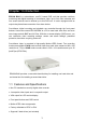
Chapter 1 Introduction EB1004 BAK is a stand-alone, non-PC based DVR unit that provides real-time monitoring and digital recording of surveillance video. Up to four video cameras and four sensor devices can be hooked up to this DVR unit. It is also equipped with an output relay that allows connection of an alarm device. Surveillance, digital recording and playback are controlled through the front panel buttons.
• Full-screen resolution: Display: 720 x 480 (NTSC), 720 x 576 (PAL) Recording: 640 x 224 (NTSC), 640 x 272 (PAL) • Display and recording frame rate: Quad mode: 30/25 fps (NTSC/PAL) per channel, total of 120/100 fps (NTSC/PAL) • Scheduled recording (00:00~23:00 set by hour ) • Search for recorded videos by date/time/event • Input/Output: 4 sensor inputs and 1 relay output control • Motion detection recording. • Removable HDD bay • 1 USB 2.
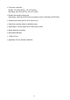
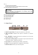
1.2 Front Panel 3 2 15 5 4 1 6 12 7 11 20 16 19 17 8 9 10 1. 12 13 18 14 REC : Start video recording. 2. 3. 4. MENU : Open/Close the OSD main menu or subsequent submenus. : Go up one item. : Go down one item. 5. SELECT : (a) Cycle through various options in a selected menu item. (b) Open a submenu 6. : (a) Display Channel 1 in full-screen. (b) Pressing this button is equivalent to entering the number "1" when in the OSD menu. 7. : (a) Display Channel 2 in full-screen.
14. : (a) Fast forward during playback. (b) Switch between the play list and the date/time search controls. 15. Removable hard disk rack with lock CAUTION BEFORE REMOVING THE REMOVABLE OR INTERNAL HARD DISK, POWER OFF THE DVR UNIT FIRST. 16. 17. 18. 19. 20. Removable Hard disk LED Removable Power LED Internal Hard Disk LED DVR Power LED USB2.0 Socket 1.3 Back Panel 1 2 3 4 7 6 5 1. VGA OUT (15-pin D-Sub): VGA output for connection to a VGA monitor. 2.
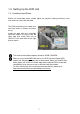
1.4 Setting Up the DVR Unit 1.4.1 Installing Hard Drives Before you install hard drives, please adjust the jumpers’ setting according to the instructions on your hard disk label. The DVR unit allows you to install up to two hard drives (a master and slave drive). Install one hard disk in a removable hard disk drawer as HDD A and the other hard disk inside DVR unit as HDD B. Fix the hard disks as the right picture shows. The minimum hard disks capacity should be 40GB/ 7200RPM.
1.4.2 Install the Hard Drive in a Removable Case 1. After unlock the removable hard disk drawer, remove the removable hard drive drawer from the case. 2. Remove the upper cover of the drawer. 3. Connect the power connector to the hard drive as the right picture shows. 4. Connect the hard disk connector into the inner tray’s slot. 5. Close the upper cover. Slide the drawer into the removable hard drive case, and lock the drawer. 6.
1.4.3 Install a Removable Hard Drive Case in a PC (Optional) For users who purchase an optional hard drive case, please follow the steps to install the case in a PC. 1. Power off your PC and remove the cover of your PC. 2. Remove a front cover and free a 5 1/4” drive bay. Insert the hard disk holder. Mount the hard disk holder, screw up the holder, and connect the IDE slot and power connector from PC’s motherboard. 3. Remove the drawer of the removable hard disk case. Please refer to 1.4.
1.4.4.1 Basic Devices • Cameras Connect the video output of each video camera or composite video source to the CH1 ~ CH4 connectors. • VGA monitor Connect a VGA monitor to the VGA OUT connector of the DVR unit to use as a display for video surveillance and playback. • Power adapter Plug the provided 110V AC or 220V power adapter into the DVR unit's power socket. 1.4.4.2 Optional Devices • Television monitor Use a BNC-to-RCA adapter to connect a regular TV monitor to the DVR unit's VIDEO OUT connector.
Terminal 9 : Connect to the positive (+) wire of the alarm device Terminal 10 : Connect to the ground (-) wire of the alarm device • Desktop/Laptop computer Connect EB1004 BAK to a PC with a USB cable. Insert the USB connector to PC’s USB socket.
Chapter 2 Operating the DVR Unit 2.1 First Time Use Connecting the DVR unit to a power outlet automatically turns on its power. When you install new hard disks in your DVR, the system will detect hard disks status and show “HDD FORMAT SELECT(YES) /MENU(NO)”. Press to format hard disks. V1-0-07 HDD Checking … MASTER 123593 MB SLAVE 123593 MB HDD FORMAT (SELECT) YES/(MENU) NO The system will show “ARE YOU SURE PLAY(FORMAT)/STOP(NOT FORMAT)” to confirm again.
Sometimes the system has trouble detecting the hard disks, it shows “Turn off and on the DVR” on the screen. Turn off and on the DVR Follow the instruction to unplug DVR. Reboot and the system will show the normal first time use screen. After you format the hard drive(s), please enter the default password before you enter the main menu. The factory default password is "111111".
EACH mode QUAD mode Use the following front panel buttons to select the desired video camera to display in full screen: CH1: Camera 1 CH2: Camera 2 CH3: Camera 3 CH4: Camera 4 Note: The recording mode can be selected in the OSD main menu. 2.3 Video Recording and Playback When you are back to the preview mode, the system will start to record the video automatically when it detects a 10-second idleness. When “PASSWORD SETUP” is enabled, you need to enter the password after clicking the STOP button.
2.3.2 To play back the recorded video 1 Press X to display the Playlist: 2 If you want to switch to the other hard drive or search for a range of video recordings, press . The ">" arrowhead cursor will then move up to the top of the screen. 3 Press 4 Press to move down to the recording date and time entries. 5 Press or to move through each item in the recording date and time entries.
Chapter 3 Setup Menu MAIN MENU > CAMERA SELECT RECORD SELECT RECORD MODE RECORD FRAMERATE VIDEO QUALITY RECORD SCHEDULE SUBMENU HARD DRIVE SETUP SENSOR SETUP 1234 1234 EACH 30 NORMAL RECORD SCHEDULE v +TTTSSSSSTTTTMMMMTTTTT+ | | | | | | | | | 0 3 6 9 12 15 18 21 24 PRESS (< , >), THEN(SELECT) PRESS (MENU) TO EXIT PRESS (< , >), THEN(SELECT) PRESS (MENU) TO EXIT SUB MENU > PASSWORD CHANGE TIME SET VGA SETUP MOTION SETUP PASSWORD SETUP NO PRESS (< , >), THEN(SELECT) PRESS (MENU) TO EXIT TIME CURRENT PA
1 Press button to display the OSD main menu. MAIN MENU > CAMERA SELECT RECORD SELECT RECORD MODE RECORD FRAMERATE VIDEO QUALITY RECORD SCHEDULE SUBMENU HARD DRIVE SETUP SENSOR SETUP 1234 1234 EACH 30 NORMAL PRESS (< , >), THEN(SELECT) PRESS (MENU) TO EXIT 2 Press or to move up or down through the items in the menu. The ">" arrowhead cursor moves as you press these buttons. 3 The first five items in the menu provide selectable settings. Press to repeatedly cycle through the available settings.
CH1: Camera 1 CH2: Camera 2 CH3: Camera 3 CH4: Camera 4 You can also press to cycle through different camera display combinations. For instance: (1 2 3 4) : Switch on all camera displays. (1 - - 4) : Switch on camera display 1 and 4 only. (- 2 3 -) : Switch on camera display 2 and 3 only. (- - - -) : Disable all camera displays. 3.2 RECORD SELECT This determines which of the cameras surveillance video will be recorded from. The way to select cameras is the same as CAMERA SELECT.
3.4 RECORD FRAME RATE This sets the number of images per second of video that is recorded. By default, frame rate is set at 30 fps for NTSC, 25 fps for PAL. There are 8-9 different frame rates you can choose from. 3.5 VIDEO QUALITY There are three video quality settings to choose from: BEST, GOOD or NORMAL. Choosing NORMAL allows you to record more on hard drive, but the quality of recorded video images is moderate.
3.6 RECORD SCHEDULE By default, the DVR unit is customized for continuous 24-hour video recording. If you prefer to record video only at certain time schedules within a day, you can choose specific recording hours. If the DVR unit is connected to sensor devices, you can also customize the unit to initiate video recording only when the sensors detect an event.
SUB MENU > PASSWORD CHANGE TIME SET VGA SETUP MOTION SETUP PASSWORD SETUP NO PRESS (< , >), THEN(SELECT) PRESS (MENU) TO EXIT 3.7.1 PASSWORD CHANGE To change the password: 1. Input the prompted information: CURRENT PASSWORD : ------ NEW PASSWORD : ------ CONFIRM PASSWORD : ------ The factory default password is "111111". Use the following front panel buttons to input a numeric password: For "1" For "2" For "3" For "4" 2. The "Password changed" message is then displayed.
3.7.2 TIME SET TIME 2004/01/10 15:30:25 ^ PRESS (< , >), THEN(SELECT) PRESS (MENU) TO EXIT To change the system date and time: 1. Press or to move through the "year/month/day" and "hour:minute:second " entries. The "^" cursor indicates the entry that is selected. 2. Per selected entry, press repeatedly to cycle through the numbers. Stop pressing the button when you reach the desired number. 3.7.
3.7.4 MOTION SETUP MOTION SETUP >MOTION CAMERA MOTION SENSITIVITY MOTION RECORD TIME ____ 01 05 PRESS (< , >), THEN(SELECT) PRESS (MENU) TO EXIT To change MOTION CAMERA, 1. Press or to move the arrowhead cursor to MOTION CAMERA in the menu. 2. Press the channel buttons to select cameras that you want to setup. To setup all cameras, press . You will see the screen shows MOTION CAMERA 1 2 3 4. Press the same button again to cancel the setting. To setup channel 1 and 4 only, press .
2. Press repeatedly to cycle through the numbers. The time setting ranges from 5 to 30 seconds. Stop pressing the button when reach the desired numbers. 3.7.5 PASSWORD SETUP SUB MENU PASSWORD CHANGE TIME SET VGA SETUP MOTION SETUP > PASSWORD SETUP NO PRESS (< , >), THEN(SELECT) PRESS (MENU) TO EXIT You can change the PASSWORD SETUP setting under the SUB MENU to enable PASSWORD SETUP.
3.8 HARD DRIVE SETUP HARD DRIVE SETUP > OVERWRITE ENABLED YES MASTER HDD SIZE 80072MB MASTER HDD USED 16014MB 20% MASTER HDD FORMAT SLAVE HDD SIZE N/A SLAVE HDD USED N/A SLAVE HDD FORMAT PRESS (< , >), THEN(SELECT) PRESS (MENU) TO EXIT 3.8.1 OVERWRITE ENABLED This allows old video recordings on the hard drive(s) to be automatically overwritten with new recordings when hard drive space is full. Press to enable or disable this feature (i.e., choose YES or NO). 3.8.
3.9 SENSOR SETUP SENSOR SETUP > SENSOR RECORD TIME ALARM OUT TIME CHANNEL-1 CHANNEL-2 CHANNEL-3 CHANNEL-4 15 05 TYPE:NORMAL-CLOSE TYPE:NORMAL-OPEN NOT INSTALLED NOT INSTALLED PRESS (< , >), THEN(SELECT) PRESS (MENU) TO EXIT 3.9.1 SENSOR RECORD TIME This determines the duration of sensor recording (in minutes) in the event that the sensor devices detect an event. There are 6 selections to choose from. 3.9.
Chapter 4 Connect to a PC EB1004 BAK provides a convenient tool to trace back the recorded surveillance video, catch specific images and save as AVI files. With the EB-DVR Playback Application, users can play back the surveillance video, catch images and backup all recorded images easily . 4.1 First Time Use Connecting DVR unit to a power outlet automatically turns on its power.
Follow the instructions to install the driver: 1. Select a language. Click Next to continue the installation. 2. Insert the CD driver into CD-ROM’s plate. It will auto-run. You will see the screen on the right side. Note: The application supports Windows 2000/XP only. 3. Click Next. Follow the steps to finish the installation. 4. Please click Browser.. to change the directory if it is necessary. Click Next to continue the installation.
5. Click Finish to complete the installation.
4.2 Operating EB-DVR Playback Application Click to run the application. Select the hard disk and then select a proper video system according to your local video system. Click OK. Attention: Make sure you enter the Main Menu before use the USB function. If you select an inappropriate video system, the video will not be normal. Please exit the playback application and then run it again. Select the hard disk and a proper video system according to your local video system.
The sequences of the DVR hard disks will vary depending on the hard disk numbers in your PC. As the following illustrations show, please select a proper hard disk sequence according to the real situation when you run the playback application. Case 1: Case 2: The sequence of HDD A will be HDD2. The sequence of HDD A will be HDD1. Case 3: Case 4: The sequence of HDD A will be HDD2. The sequence of HDD A will be HDD1. Case 5: Case 6: Insert HDD A into the PC. The sequence of Insert HDD A into the PC.
HDD A will be HDD2. HDD A will be HDD1. Case 7: Case 8: Place HDD B in the removal hard disk drawer. The sequence of HDD B will be HDD2. Place HDD B in the removal hard disk drawer. The sequence of HDD B will be HDD1.
You will see EB-DVR screen as followed. 1. Channel 1- Channel 4: Switch between cameras. 2. Change Driver: Switch between different hard disks. 3. Event List: Display all the recorded events stored in hard disks. 4. Play: Play the recorded video. 5. Backward play: Play the video backward. 6. Pause: Pause the playback. 7. Play one frame: Display a forward static frame. 8. Back one frame: Display a backward static frame. 9. Forward Search: Fast play the recorded video to search an appointed image. 10.
Attention: When you want to read the data in the HDD A via a USB cable directly without removing the hard disk, follow the following picture to connect the hard disks in the DVR. When you need to read HDD B via a USB cable. Please plug the middle connector of IDE cable in HDD B and the other connector to HDD A as the following picture. Without removing the hard disk, your PC can read the data in HDD B. Use the playback application to play the video data by PC. 4.2.
the sensor detects an event. Event List enables you to playback any recorded event anytime. Record Mode Start Time End Time When you decide which event to play, click to display the video or click to display a recorded dynamic event reversely. Click to search the appointed video. Users can select the forward search mode fast play at 2X, 4X or 8X speed. Click once to fast play the video at 2X. Click twice to fast play the video at 4X. Click 3 times to fast play the video at 8X.
Click to pause the playing. Click to stop the video. 4.2.3 Catch Images and Video EB-1004 BAK Playback Application provides functions to output both dynamic and static images. Users can easily catch a static screen and save it as a BMP file, or save some fragment of recorded video as an AVI file. 4.2.3.1 Snapshot Click to save the desired screen as a BMP file. Users can keep a full-screen snapshot or a quad screen snapshot. This function allows to preserve static images. 4.2.3.
Warranty Notice LIMITED WARRANTY AVerMedia TECHNOLOGIES, Inc. warrants this product to be free of defects resulting from faulty manufacture or components under the following terms: WARRANTY LENGTH Labor is warranted for (1) one year from the date of purchase. Parts are warranted for (1) one year from the date of purchase. Replacement products will be warranted for the remainder of the one year warranty period or (30) thirty days, whichever is longer.