AVerMedia® XR8032 User’s Manual
FCC NOTICE (Class A) This device complies with Part 15 of the FCC Rules. Operation is subject to the following two conditions: (1) this device may not cause harmful interference, and (2) this device must accept any interference received, including interference that may cause undesired operation. Federal Communications Commission Statement NOTE- This equipment has been tested and found to comply with the limits for a Class A digital device, pursuant to Part 15 of the FCC Rules.
WARNING TO REDUCE RISK OF FIRE OR ELECTRIC SHOCK, DO NOT EXPOSE THIS APPLIANCE TO RAIN OR MOISTURE. CAUTION IF THERE IS ANY DAMAGE, SHORTAGE OR INAPPROPRIATE ITEM IN THE PACKAGE, PLEASE CONTACT WITH YOUR LOCAL DEALER. WARRANTY VOID FOR ANY UNAUTHORIZED PRODUCT MODIFICATION. Manual Conventions The following conventions are used throughout this manual Caution symbol is intended to alert the user of the important installation and operating instructions. Fail to comply may damage the system.
TABLE OF CONTENTS Chapter 1 Introduction................................................................................ 1 1.1 1.2 1.3 1.4 1.5 1.6 Package Contents ..................................................................................................... 1 Front Panel ................................................................................................................ 1 Back Panel..........................................................................................................
3.8 Relay Setting ........................................................................................................... 39 3.9 Alarm Setting ........................................................................................................... 39 3.9.1 To Setup Alarm Relay:................................................................................... 43 3.9.2 To Setup the Alarm Sound Setting: ............................................................... 44 3.9.3 To Setup Call Out List: ...
Chapter 9 Web Tools................................................................................. 76 9.1 Dispatch Server ....................................................................................................... 76 9.2 Remote Backup ....................................................................................................... 76 Chapter 10 Using the Remote Control Server .................................... 79 Appendix A Registering Domain Names.....................................
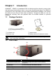
Chapter 1 Introduction AVerMedia® XR8032 is a standalone DVR unit that through the network to receive video and monitoring and recording of video. It can connect 8 sensors and relays. The XR8032 is customized to use it right away. No more software and hardware installation. Just connect the cables and you may now start video surveillance. Through the USB port, user can backup the recording video and playback within the bundled software on personal computer. 1.
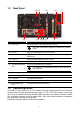
1.3 Back Panel (8) (7) (11) (10) (9) (6) (5) Name (1) Audio Out (4) (2) (1) (3) Function Output the audio of the selected video channel i The audio output device needs to be powered by external power.
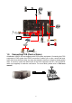
CCTV Monitor Microphone Pen drive/ External hard disk Switch External I/O Box CRT/LCD Monitor Sensor 1 Sensor 8 Alarm 1 Alarm 8 Inte rnet web viewer 1.5 IP Camera 1 IP Camera 32 Connecting POS (Point of Sales) AVerMedia® XR8032 can be integrated with POS system equipment. Connecting the POS equipment to DVR system thru RS232 connection, enables you to view, record and keep track of the items that were sold. You may also select the camera on where to display all the data.
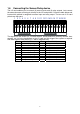
1.6 Connecting the Sensor/Relay device The I/O card enables you to connect (8) sensor inputs and (8) relay outputs. Just connect the external sensor and relay pin directly to the I/O card pinhole. Check the table below and locate which pinhole is assigned to sensor input and relay output. The two set of I/O card pinhole are the same. 1 2 3 4 5 6 7 8 9 10 11 1213 1415 16 17 1819 20 RELAY OUT SENSOR IN The signal from the sensor (i.e.
Chapter 2 2.1 Using the DVR Software Running the Unit for the First Time When the unit is turned on for the first time, the system will prompt you to enter the serial number. The serial number is inside the package. 2.2 Function buttons of Advanced/Preview Mode (17) (16) (15) (14) (13) (12) (18) (11) (10) (1) Name (1) Exit (2) Volume (2) (3) (4) (5) (6) (7) (8) (9) Function Call up the Logout dialog box.
Name Function (3) Split Screen Mode It provides 7 kinds of split display modes for your selection. You can select one of the split display modes by clicking the following icon. 1-Cam display 4-Cam split display 9-Cam split display 16-Cam split display 8-Cam split display 13-Cam split display 32-Cam split display (4) Record to start recording. The button turns violet when it is Click recording.
Name (16) Full screen Function Click it to turn to full screen mode. To return, press the right button of the mouse or ESC on the keyboard or click the arrow icon. Click the arrow icon to leave from full screen display mode When you switch to full screen in multiple-screen mode, Left click to toggle to only display one of the video in the multiple-screen mode or all. (17) Alarm Click (18) On Screen Keyboard If the keyboard is not available, you may use the Virtual Keyboard. 2.2.
(6) (1) (2) (3) (4) (5) Name (1) POSDB Path (2) Before/After (3) Channel (4) Search String (5) Full Reception (6) Search Result Function The storage path for POS event log. Click to change the storage path. Set a time period before and after of POS event log. Select the POS event log of channel Enter specific key word or word string to search the POS event log. Mark the “Match whole word exactly” box if wants to find exactly key word or word string of POS event log.
2.3 Familiarizing the Buttons in Playback Mode To switch in Playback mode, click Playback button at the lower right corner of Advanced/Preview mode user interface Name (1) Split Screen Mode i - If there are only 4 cameras, you won’t be able to switch to 9, 13, and 16 split screen mode. To zoom in an area on the screen, Right click and Drag a square on the area you want to enlarge.
Name (4) Playback Control Buttons Function Faster: Play the recorded video file at the speed of 2x, 4x, 8x, 16x or 32x. Next: Go to the next frame. End: Go to the end of the recorded video file. (5) Date Select the date on the calendar and the time from 00 to 23 to where to start playing the recorded video file. i The numbers from 00 to 23 represent the time in 24-hour clock. The numbers from 01 to 16 represent the camera ID.
Name Function You can use this when you are using Intelligent Search or Event Search function. (19) Event Search Search from the recorded activities that take place in the system (i.e., Sensor, Motion, Video Loss, POS). (See also 2.10) (20) Intelligent Search Search the changes in the motion detector frame (See also 2.11). 2.4 Familiarizing the Buttons in Compact Mode To view in Compact mode, click Exit button. In the logout dialog box, click Compact.
(5) Advanced 2.5 Switch to Preview/Advanced mode. Familiarizing the Buttons in PTZ Camera Controller (4) (3) (2) (1) (5) (10) (6) (7) (8) (9) Name Function (1) Close Exit PTZ camera controller. (2) AutoPan Operate the PTZ cameras automatically based on the selected camera group preset position number. (3) Focus +/- Adjust the focus manually to produce clear image. (4) Zoom +/- Zoom in and out the image. (5) Direction buttons Adjust and position the focal point of the PTZ camera.
camera, sensor, and relay icons to its place on the map. Icons on the map can be relocated anywhere. Right click camera icon can select the camera direction in 8 angles. If you are going to locate the icon on the map to other area, you need to drag the icon to the black pane at the bottom of the Emap screen and then switch to the area on where you want to locate the icon. To bring all the icons back to the black pane at the bottom of the Emap screen, click Reset Icon. 4.
again. 3. 4. Click Output button to save the wanted clip. In the Save As dialog box, locate on where you want to save the file, type the filename, and select the video format. 2.8 1. 2. i 3. 2.9 To Bookmark a Section of the Video Click Bookmark. The video playback stops when the bookmark button is executed. In the Bookmark dialog box, you may do the following: Add to include the new reference mark in the bookmark list. You may select to enable/disable file protection.
2.10 To Search Using the Event Search 1. 2. 3. 4. 5. Click on the video screen on where you want to search. Click Event Search. The Event Search text (red) would appear at the lower left corner of the screen. In the Event Search Setting dialog box, check the type of condition you want to search. If you select POS, in the Find Text box, type the word. Then, click OK to start searching. The video search would stop at the frame that matches the condition. To keep on searching click .
2.12 To Setup the PTZ/IP PTZ Camera 2.12.1 Setup the PTZ Camera 1. In the PTZ control panel, click Setup. 2. When the PTZ Setup dialog box appears, select the camera number and check the Use PTZ box. 3. In the Connection Settings section, select the COMPort where the PTZ camera is connected, PTZ ID number and PTZ camera protocol. Then, click Save to keep the settings. 4. Use the PTZ control panel and adjust the position of the PTZ camera. 5.
3. Select the camera number and check the Use PTZ box. 4. In the Connection Settings section, select the Protocol where the PTZ camera is connected and IP Camera Site that IP or URL of IP camera. Then, click Save to keep the settings. 5. Use the IP PTZ control panel and adjust the position of the IP PTZ camera. 6. In the Preset Setting section, select the preset number to assign a number for the IP PTZ camera current position.
Chapter 3 Customizing the DVR System In the Preview/Advanced screen mode, click button to customize your DVR. When the DVR configuration setup selection appears, select and click the buttons you want to change the setting. 3.1 System Setting In the System Setting dialog box, click OK to accept the new settings, click Cancel to exit without saving, and click Default to revert back to original factory setting.
time in Expected HD Size or Expected Record time, and then click Calculate button. Click OK to exit the hard disk calculator windows. The hard disk calculation will base on the recording setup and current hard disk setup. (3)Language Customize the system to display the tool tips and dialogs based on the selected language. By default the language is in English. (5) Attention Please Check the attentiveness of the person who is monitoring the system.
(1) (2) (3) (4) ~ Fixed Layout (1) Select the channel group from drop down list. If only have 16 cameras or less 16 cameras, there is only one channel group in the drop down list. (2) Select the display mode as FixedLayout. (3) Preview screen: the selected camera video will preview in here. (4) Video Mode: Select the split mode of TV out display. (5) Cameras: User can select the cameras that user wants to display on the screen. Only those selected channels would be displayed on the screen.
click Setup. - Beep if no signal Make sound when the video signal is lost. - Mandatory Recording Always recording the video in any condition. - Enable Overlay To enhance video signal for better video quality. - Playback Mode Select the mode of playback the video. Select date and time: Select the date and time which user wants to playback.
2. In the POS Mapping dialog box, click OK to accept the settings and Cancel to exit without saving the new setting. (1) (2) (3) (4) (5) (6) (7) (1) POS Name (2) Protocol (3) Skip first (4) Setup… : Enter a name to identify the POS : Select General for Epson compatible printer or for TP_3688 : Set the number of lines you want to be removed : Set the COM Properties.
(6) Map to Channel: Select to which camera number to display the transaction text (7) Text Filter : Enter the word you want to be removed 23
3.2 Camera Setting In the Camera Setting dialog box, click OK to accept the new settings, click Cancel to exit without saving, and click Default to revert back to original factory setting. (1) (2) (3) (8) (4) (5) (9) (11) (13) (6) (7) (10) (12) (1) Camera Icons Select the camera number you want to adjust the video setting. To select all the cameras, enable the ALL check box. To select more than one camera, Right click on the camera icon. To select one camera only, Left click on the camera icon.
- Authentication: Mark check box and enter the ID and password for authorizing to connect the camera. Only if the camera has assign the ID and password for authentication. (5) Camera Information Display the camera information, such as camera protocol, model, video type, IP address, and channel number. If the camera hasn’t been configured, those information are blank. (6) Enable Audio Enable/disable camera audio recording.
(10) Video Adjust the video setting of the selected camera. Click Video Setting to enter video adjustment interface. Video Setting Adjust the Frame Rate, Quality, Bright, Contrast, Hue, and Saturation. Recording Setting Save Original Format: Save the video that is compressed by IP camera’s compress mode. 9 Only decode key frame for Preview: When selected the Save Original Format selection, user can mark Only decode key frame for Preview this option.
(12) Sensor Setting To setup sensor that is embedded on the camera. 1. Click the drop-down list and select the sensor ID number. 2. Enter sensor name. 3. The system automatically detects the camera and input relates information. In the Content section, enter sensor description. 4. In the test section, click Test to check the sensor status. Red is high and Green is low. 5. Click OK to exit and accept the setting and Cancel to exit without saving the setting.
3.2.1 Setup the Object Counting 1. Click Detail to enter the object counting setup window. 2. Enable Detected Regions in Display section. This enables the object counting information show on the screen. Moving Object will enable the object size frame to show on the screen. 3. Click Region1 and press left button of mouse and drag the area that user wants the object to be counted. And then, click Region2 and drag another area that user wants the object to be counted, too.
without saving, and click Default to revert back to original factory setting. (1) (2) (7) (3) (8) (4) (9) (5) (10) (6) (1) Camera Icons Select the camera number you want to set the recording setting. To select all the cameras, enable the ALL check box. To select more than one camera, Right click on the camera icon. To select one camera only, Left click on the camera icon. The camera icon turns red when it is selected. (2) Recording Mode The blocks from 00 to 23 represent the time in 24-hour clock.
(5) Frame Rate Set the maximum number of frames to be recorded during motion and motionless state. The frame rate ranges from 1 to 30 for NTSC and 1 to 25 for PAL. The higher the frame rate, it uses more hard disk space. available when user selected “Transcode by MPEG4 Encoder” in Video i Only Setting at Camera setting section(see Chapter 3.2 #9) (6) Video Size You can activate the Enable Deinterlace to enhance the video quality.
3. i Click and drag a frame on the (7) Video Screen to create Mask or Shield area. Shield is only available when user selected “Transcode by MPEG4 Encoder” in Video Setting at Camera setting section(see Chapter 3.2 #9) 3.3.2 1. 2. To show and change the color of the Mask: Enable the Show Mask check box. In the Color section, select the color and click ~button. 3.3.
3.4 Network Setting In the Network Setting dialog box, click OK to accept the new settings, click Cancel to exit without saving, and click Default to revert back to original factory setting. (1) (7) (2) (8) (3) (9) (4) (5) (10) (6) (1) Server Name Assign a name for the DVR unit. Alphabet letters and numbers only.
using this feature. If the Talk to Web-Client is disabled, the person in the DVR server side can only hear the voice from the client side that is when the WebViewer 2-Way Talk button is activated (see also 6.1 #6). i Make sure that your Webcam Digital Signature is updated yearly; else you won’t be able to access the DVR server from the DVR WebViewer. To update/download your WebViewer Digital Signature, click Update WebViewer Digital Signature. Make sure your PC is connected to internet.
3.5 Schedule Setting Schedule to record, backup, enable network, reboot and disable alarm of all the cameras either weekly or one time. The number from 00 to 23 represent the time in 24-hour clock. The left most column display the days in a week. To Set the Schedule Setting: 1. Select the date in the calendar. Use and buttons to shift the calendar to the left or right. 2. Select the condition you want to schedule in the drop down list.
3.5.1 1. 2. 3. 3.6 Set schedule at specific portion of time Right click the colored blocks. In the Select time dialog box, click to enable or disable the portion you want to set. Click OK to accept the setting and Cancel to exit without saving the setting. Backup Setting In the Backup Setting dialog box, the number from 00 to 23 represent the time in 24-hour clock. The numbers from 01 to 16 represent the camera number.
9. 3.7 In CD/DVD Backup, enable/disable Delete file after burning check box to remove the archived file after burning. Click Burn to start and Exit to cancel this process. Sensor Setting The I/O device must be installed to use this function. To Set the Sensor Setting: 1. Click the drop-down list and select the sensor ID number. 2. Enter sensor name. 3. Click External IO to configure external I/O device if it is available(see also 3.7.1) 4.
3.7.1 To Setup External I/O Box The DVR system can connect the external I/O box for more installed of I/O devices. 1. 2. 3. 4. Click Add. Mark Enable box to enable this external I/O box. Select the Brand of external I/O box from drag down list. In Port Setting, different brand of external I/O box may have different port parameters. Please refer to the external I/O box’s user manual for port setting information. Using the default value if user uses AverMedia External I/O box. 5.
9. All connected relays and sensors will be listed. User can click radio button to control relays’ status. And then, click OK to save the setting and click Cancel to exit and without saving. 10. All connected External I/O box and their modules will be listed as tree topology in External I/O Setup windows.
11. To view the all I/O devices information, click I/O Map. 3.8 Relay Setting The I/O device must be installed to use this function. To set the Relay Setting: 1. Click the drop-down list and select the relay ID number. 2. Mark Enable to enable the selected relay. 3. Click External IO to configure external I/O device if it is available (see also 3.7.1). When external I/O is set and it will be available in drag down list for selecting. 4. The system automatically detects the card and input number.
(1) (2) (3) (7 ) (4) (5) (6) To set the Alarm Setting: 1. Click Add to insert and set a new alarm setting. Click the items in the (7) Alarm Setting List, if you want to modify the alarm setting. 2. In (1) Alarm Setting number/Name/Description, display the selected alarm setting number in the list below. Enter alarm name and description. 3. In (2) Enable Time, the number from 00 to 23 represent the time in 24-hour clock.
- Enable/disable the Abnormal Event check box, to set the condition of the event for system to alarm. • Normal Reboot: when the DVR system reboot without abnormal condition, the system will send out the alarm message. • Abnormal Reboot: when the DVR system reboot in irregular condition, the system will send out the alarm message. • Recording is switched off: when the recording has been stopped, the system will send out the alarm message.
normal status is high, set the sensor condition to low. Click IP Cam Sensor to IP camera sensor reset condition. Click High or Low column to set the reset condition of alarm. 7. In (6) Action, you may now set the alarm action for the system to perform when the alarm condition is activated. Launch E-Map Display mini Emap screen. TV Out Switch to only display the video on TV from where the alarm is activated.
- - - - - - 3.9.1 1. 2. 3. 4. Upload file to remote computer thru FTP (File Transfer Protocol). To setup click Detail (see also 3.9.5). Start Recording Record the video from the selected camera. To setup click Detail (see also 3.9.6). SMS (Short Message Service)/MMS (Multimedia Messaging System) SMS transmits only text messages to mobile phone. MMS transmits text messages and images over wireless networks using the wireless application protocol (WAP).
3.9.2 1. 2. To Setup the Alarm Sound Setting: Beside the Play Warning Sound check box, click Detail. In the Alarm Sound Setting dialog box, click to select other wav file from other source or folder, Play to listen, Record to make a new copy of a sound. 3. If you click Record, you will be prompted if you want to replace the file. Click OK to continue and Cancel to discontinue. 4. When the Sound Recorder appears, use the record control panel to record, stop, play, rewind and forward.
6. 7. you have microphone connected to your PC. The supported audio system is only 8KHz and 16Bit mono. Click OK to exit and accept the setting and Cancel to exit without saving the setting. 3.9.4 To Setup Send E-mail Setting: Beside the Send Email check box, click Detail. In the E-mail Setting dialog box, click OK to exit and save the setting and Cancel to exit without saving the setting. (1) (2) (3) (4) (1) Mail Server Enter the SMTP Server and port.
sensor is triggered. Click OK to exit and save the setting and Cancel to exit without saving the setting. 5. 3.9.6 1. To Setup Alarm Recording Setting: Beside the Start Recording check box, click Detail. In the Alarm Recording Setting dialog box, select the camera to enable/disable video recording. Enable All to select all cameras.
3.9.9 To Setup Alarm SOP: Beside the Alarm SOP check box, click Detail. In the step text boxes, type the standard protocol when the alarm is activated. When the alarm is activated the Standard Operation Procedure dialog box will appear. Just click Next to see the next instruction, Back to see the previous instruction, Finish to end and Abort to terminate. 3.9.10 To Setup CMS Setting Beside the Send to CMS check box, click Detail.
Click to change color of keyword 3.9.12 Missing and Suspicious Object Detected - Missing Object Select the certain object on the screen for the system to detect; when the object is disappear or move and the system will alarm. Click OK to exit and save the configuration. To exam the setup condition, click Start Test. 1. Select the camera number (0-16) and press RIGHT button on the mouse to call up the setup windows. 2. Click Save to capture the image for comparing reference first.
- 2. Click Save to capture the image for comparing reference. To view the captured image, enable the Show Reference Image check box. The captured image will display on screen. The reference image is sharing with the Missing Object and Scene Change function. 3. Mark the Enable check box to setup the condition. 4. Sensitive: Set the system detects sensitivity. 5. Delay Time: Set the lasting time for system to detect the object. 6. Use the mouse to click and drag the frame on the screen.
3.10 User Setting Only administrator can access User Setting. The maximum user accounts are 256. In the User Setting dialog box, click Add to insert a new user, Delete to remove the selected user, Edit to modify the user control right, OK to exit and accept the setting, and Cancel to exit without saving the setting. After clicking Add or Edit, you may customize the user control setting.
(4) Visible Camera Select the camera number that would allow the user to access or view. enable the ALL check box. (5) Name Enter the user name. (6) Description Enter the user description. (7) Password Enter the user password. (8) Confirm Password Enter the same user password for confirmation.
Chapter 4 Backup Video Players You can playback the backup files using QLogViewer and Player applications. When you back up the recorded file, QLogViewer and Player applications are automatically included in the backup folder. QLogViewer can only playback one video at a time. It only comes with video segmentation, output segmentation, capture screen shot, and print the screen.
Name Function (3) Playback Control Buttons Slower: Play the recorded video file at the speed of ½x, ¼x, or ⅛x. Rewind: Wind back the recorded video file. Pause: Briefly stop playing the recorded video file. Play: Play the recorded video file. Faster: Play the recorded video file at the speed of 2x, 4x, or 8x. Next: Go to the next frame. End: Go to the end of the recorded video file. (4) Progress bar Show the progress of the file being played. You may move the bar to seek at any location of the track.
Name Function (3) Progress bar Show the progress of the file being played. You may move the bar to seek at any location of the track. (4) Hour Buttons Select and click to playback the recorded video file on the specific time frame. (5) Playback Control Buttons Begin: Move at the beginning of the recorded video file. Previous: Go back to the previous frame. Slower: Play the recorded video file at the speed of ½x, ¼x, or ⅛x. Rewind: Wind back the recorded video file.
Chapter 5 Using Functional Keys The DVR system provides shortcut keys. The table shows the function keys and descriptions.
Chapter 6 Using the Remote Programs You can use Microsoft Internet Explorer to access DVR server by entering the IP address or domain name. To use this feature, make sure that you are connected to the internet and the Network feature is enabled. Accessing this feature for the first time you will be prompted by your browser to install WebCamX.cab, allow the installation and you should be able to connect and login afterwards. For Windows 2000, click Yes when the Security Warning dialog box appears.
6.1 Familiarizing the WebViewer Buttons Right-clicking on the webcam video screen, enables you to start video recording, change video quality, switch camera and enable/disable DirectDraw. (15) (14) (13) (12) (11) (10) (9) (8) (1) Name (1) DirectDraw i (2) (4) (3) (5) (6) (7) Function Enhance the video quality. Not all graphic cards can support this function. (2) Received file size Indicate the size of the data being sent per second.
Name Function (13) Snapshot Capture and save the screen shot in *.bmp format. (14) Full screen Use the entire area of the screen to only display the video. To return, Right click the mouse or press ESC on the keyboard. (15) Select cameras to view Select to the view camera from different server. In Select Camera dialog box, Display column, click to enable/disable viewing the camera. In Video Quality column, click to select between High, Normal or Low.
Enable/disable to show the video. Even if the video of the selected camera is hidden you can still record the video and preview it in playback mode. - Name Change the camera name. - Description Add a short comment. (4) Video Adjustment Adjust the Brightness, Contrast, Hue and Saturation of the selected camera. (5) Recording Setting Select the size of the video and click the ~ button. The higher the size, the larger the file it create.
Name Function (4) Camera preset position number Move the PTZ camera to the preset point. (5) Zoom +/- Zoom in and out the image. (6) Focus +/- Adjust the focus manually to produce clear image.
6.3 Familiarizing the Remote Console Buttons (15) (14) (13) (12) (11) (16) (10) (9) (1)(2) (3) (4) (5) (6) (7) (8) Name Function (1) Exit Close the Remote Console. (2) Volume Enable/disable the sound. (3) Split Screen Mode Select from 6 kinds of split screen type to playback the recorded video file of all the camera, or one camera over the other or alongside on a single screen. To view 32 channels, click 16 split screen button to switch channel display.
Name Function (14) Full screen Use the entire area of the screen to only display the video. To return, Right click the mouse or press ESC on the keyboard. (15) Alarm Alert and display warning info. Only Administrator-level can reset and turn on, off and trigger the Sensor and Relay by right-clicking the item in the Sensor and Relay list. (16) Direct Draw Enhance the video quality. i 6.3.1 Not all graphic cards can support this function.
6.4 Using the Remote Playback To use this feature, first you need to select the source of the file. In the Select Playback Mode dialog box, choose Local Playback to open the file that is recorded in the Remote Console, and Remote Playback to open the file that is recorded in the DVR server. When you choose Remote Playback, select RealTime Playback if your internet bandwidth is fast and big enough, otherwise choose Download and Playback. Click OK to proceed and Cancel to void this operation.
selected hour into 16 video thumbnails. In the Time Selection screen, click on the video thumbnail you want to download and open (see also 6.4.2). 6.4.1 Familiarizing the Local Playback Buttons (13) (12) (11) (10) (9) (8) (7) (1) (2) (3) (4) (5) (6) Name Function (1) Split Screen Mode Select from 6 kinds of split screen type to playback the recorded video file of all the camera, or one camera over the other or alongside on a single screen.
Name (4) Playback Control Buttons Function Begin: Move at the beginning of the recorded video file. Previous: Go back to the previous frame. Slower: Play the recorded video file at the speed of ½x, ¼x, or ⅛x. Rewind: Wind back the recorded video file. Pause: Briefly stop playing the recorded video file. Play: Play the recorded video file. Faster: Play the recorded video file at the speed of 2x, 4x, 8x, 16x or 32x. Next: Go to the next frame. End: Go to the end of the recorded video file.
6.4.2 Familiarizing the RealTime Playback Buttons (11) (10) (9) (8) (7) (1) (2) (3) (4) (5) (6) Name Function (1) Split Screen Mode Select from two (2) different split screen type to playback the recorded video file of all the camera, or one camera. To view all channels, click 4 split screen button to switch channel display. i To zoom in an area on the screen, Right click and Drag a square on the area you want to enlarge.
Name Function (6) Preview Switch to Preview/Advanced mode. (7) Playback Switch to Playback mode. This allows you to view the recorded video file. (8) Status bar Display the recorded date, time and play speed. (9) Camera ID Show the number of cameras that are being viewed. When you are in single screen mode, click the camera ID number to switch and view other camera. (10) Snapshot Capture and save the screen shot either in *.jpg or *.bmp format. (11) Full screen View in Playback-compact mode.
Name Function (5) Print Print the screen shot. (6) Save Save the screen shot either in *.jpg or *.bmp format and video in *.dvr format. (7) Segment Keep a portion of the recorded video you want. You may follow the instruction in 2.7. 6.5 Using Handy Viewer to Access DVR Server Users can use a mobile phone to access the DVR through Internet. Make sure your mobile phone support IE browser and is connected to the internet.
3. Read the license agreement and click Yes to accept all the terms. The system will then automatically install the application. 4. When you are prompted, click Yes to install the application using the default directory. 5. When done, click OK. 6.6.2 1. 2. To install PDA Viewer from the Internet Make sure you are connected to the internet. Open the web browser and enter the server IP. Then click the hyperlink Download PDA-Viewer. 3.
6.6.3 1. 2. 3. To Use the PDA Viewer Run the PDA-Viewer 5.5 in the Programs. Familiarizing the PDA Viewer buttons. (2) (1) (3) (4) (5) (10) (9) (8) (6) (7) Name Function (1) Connect Hook up to the DVR server. Make sure you are connected to internet. When the iView screen appears, enter the server IP, port, user ID, password and select the connection type. Then, click OK. (2) Split Screen Mode Select between 2 screen display types.
6.7 Using Java-Viewer to Access DVR Server Using the mobile phone within Symbian Smart Phone OS to access the DVR through Internet. Make sure your mobile phone supports Symbian Smart Phone OS and can be connected to the internet. To use this feature, you need to install the JAVA Viewer program that it can be downloading it from the DVR server through the internet. 6.7.1 To install JAVA-Viewer from the DVR Server 1.
4. Click Yes to accept the data from DVR server. 5. When connection is success, you will see the camera video on the screen. 6. To switch to different camera view, select menu and select the channel. 7. The JAVA-Viewer support PTZ control function, you can refer to Help file for detail function control key. Select menu and go the way down to select the Help file.
Chapter 7 Image Verification ImageVerification is a watermark-checking program to identify the authenticity of a saved image (e.g. by snapshot). This program can only verify uncompressed bmp image files. 7.1 1. 2. 3. 4. To Run the ImageVerification program Click Start > Programs > DSS > ImageVerification. In the ImageVerification screen, click Load Source Image and locate the image source. Click Verify Image to begin the process. Check the result in the Processed Image screen.
Chapter 8 iEnhance The bundled iEnhance is a video editing tool and can only be used with *.dvr video file. It allows you to adjust the video picture quality, segment and save the wanted portion of the video, zoom in and out the image, and print or save the screen shot. You can also save the setting and apply it on other files.
Name (14) Effects (15) Picture Adjustment (16) Original Screen (17) Temporary Setting Block (18) Status Bar (19) Progress Bar (20) iStable (21) Add Setting (22) Rename (23) Delete (24) Load Setting (25) Save Setting Function • Gray Scale: convert the image into black and white (monochrome). • Normalize: adjust the brightness intensity. • Equalize: automatically adjust the images that are too dark. • De-interlace: smooth out the overlying frames. • Static: de-interlace for motionless scene.
Chapter 9 Web Tools The bundled Web Tools includes Dispatch Server and Remote Backup program. To install Web Tools, place the CD into the CD-ROM drive then click Install Web Tools. 9.1 Dispatch Server Dispatch is designed to reduce the network traffic of the DVR server. Instead of connecting directly to the DVR server, the client can connect to the computer that is connected to the DVR server using the Dispatch program. To Run Dispatch program: 1. Make sure you are connected to the internet. 2.
4. In the Add New DVR windows, enter the Name, IP, user ID, and password. 5. Select the Backup mode: Auto Backup mode: the backup will automatically execute when the setup is completed - In Begin Date drop down calendar, select the date from where to start - Click Add to set the storage path. - Click Delete to remove the selected storage path. - Click Schedule to select/unselect the time you want to backup. The red block turns white when it is unselected.
Un-mark check box to disable backup Click to start backup 7. Click Start to begin backup and click Stop to stop backup progress. While backup, the start button will turn to stop button 8. For manually backup, click file select button and select the DVR wants to backup.
Chapter 10 Using the Remote Control Server The bundled Remote Control Server enables the PC with Central Management System program (CM1000) installed in it remotely access the DVR server. You many need to manually run this program for CMS access the DVR server. To run, click start > Programs > DSS > DVR > Remote Control Server. remote control server icon appears on the taskbar when the remote control server The is enabled.
Appendix A Registering Domain Names DDNS (Dynamic Domain Name Service) is a data query service mainly used on the Internet for translating domain names into Internet addresses. It allows remote clients to intelligently search dynamic servers without any previous enquiring for servers’ Internet addresses. In order to take advantage of this intelligent service, first register your domain name on the following Web site http://ddns.avers.com.tw 1. User Login Browse the website ddns.avers.com.
Warranty Notice LIMITED WARRANTY AVerMedia® TECHNOLOGIES, Inc. warrants that this product to be free of defects resulting from faulty manufacturing or components under the following terms: WARRANTY LENGTH Labor is warranted for 15 months from the date of purchase. Replacement products will be warranted for the remainder of the 15-month warranty period or 30 days, whichever is longer. WHO IS PROTECTED This warranty is enforceable only by the first consumer purchaser.