AVerMedia® XR8032 RACK User’s Manual March 2009
FCC NOTICE (Class A) This device complies with Part 15 of the FCC Rules. Operation is subject to the following two conditions: (1) this device may not cause harmful interference, and (2) this device must accept any interference received, including interference that may cause undesired operation. Federal Communications Commission Statement NOTE- This equipment has been tested and found to comply with the limits for a Class A digital device, pursuant to Part 15 of the FCC Rules.
WARNING TO REDUCE RISK OF FIRE OR ELECTRIC SHOCK, DO NOT EXPOSE THIS APPLIANCE TO RAIN OR MOISTURE. CAUTION IF THERE IS ANY DAMAGE, SHORTAGE OR INAPPROPRIATE ITEM IN THE PACKAGE, PLEASE CONTACT WITH YOUR LOCAL DEALER. WARRANTY VOID FOR ANY UNAUTHORIZED PRODUCT MODIFICATION. NOTICE - INFORMATION IN THIS DOCUMENT IS SUBJECT TO CHANGE WITHOUT NOTICE. - THE INFORMATION CONTAINED HEREIN IS TO BE CONSIDERED FOR REFERENCE ONLY.
TABLE OF CONTENTS Chapter 1 Introduction ................................................................................................ 1 1.1 1.2 1.3 1.4 Package Contents ........................................................................................................................ 1 Front Panel................................................................................................................................... 1 Back Panel ...........................................................
3.9.1 To Setup Alarm Relay: ..................................................................................................... 68 3.9.2 To Setup the Alarm Sound Setting ................................................................................... 68 3.9.3 To Setup Call Out List: ..................................................................................................... 68 3.9.4 To Setup Send E-mail Setting: ..................................................................................
9.2.1 To Add DVR server .........................................................................................................119 9.2.2 To Setup Remote DVR Server ....................................................................................... 120 9.3 Remote iBackup ....................................................................................................................... 133 9.4 iMatrix Application .......................................................................................
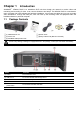
Chapter 1 Introduction AVerMedia® XR8032 RACK is a standalone DVR unit that through the network to receive video and monitoring and recording of video. It can connect 8 sensors and relays. The XR8032 RACK is customized to use it right away. No more software and hardware installation. Just connect the cables and you may now start video surveillance. Through the USB port, user can back up the recording video and playback within the bundled software on personal computer. 1.
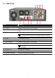
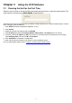
1.3 Back Panel Name Function (1) Ethernet Port For WAN/LAN connection (2) TV Out Output the video signal to a CCTV monitor (3) Sensor In Relay Out Support 8 sensor devices and 8 relay devices (Relay: 1A @ 125V AC/30V DC) (4) Audio Out Output the audio of the selected video channel i The audio output device has its own power supply is necessary.
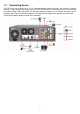
1.4 Connecting Device The DVR unit can connect up to 32 IP cameras through internet and also can connect 8 sensor devices, 8 alarm device and output video to a CRT/LCD monitor. Connecting the unit to an external hard disk through USB connection, the bundled software enables you to transfer and back up the recorded video. Also, the bundled software can playback and segment the backup recorded video.
Chapter 2 2.1 Using the DVR Software Running the Unit for the First Time When the unit is turned on for the first time, the system will prompt you to enter the serial number. The serial number is located on the REAR PANEL of the DVR unit. After entered the serial number, the main surveillance interface will show up. Follow the below steps to connect the IP cameras to start surveillance. 1. Click SETUP and enter the password (default is 111111) 2. Click Camera 3.
2.2 Function buttons of Advanced/Preview Mode Name (1) Exit Function Call up the Logout dialog box. In the logout dialog box, you may do the following: (1) Exit (2) Volume - Click Exit to shutdown the DVR system. Click Reboot to restart the DVR system Click Login to sign-in in different account. Click Compact to switch to compact mode (see 2.4). Click Guest to switch to the guest authority level. In guest authority level, user only allow to preview and playback the recorded video.
Name Function (3) Split Screen Mode Select from 7 different split screen types to view all the camera, or one camera over the other or alongside on a single screen. It also allows you to switch and view different camera number. 1-Cam display 4-Cam split display 9-Cam split display 16-Cam split display 8-Cam split display 13-Cam split display 32-Cam split display (4) Record Start/stop video recording. (5) E-Map Display the map in each area, and the location of camera/ sensor/ relay and the warning.
Name Function (12) Camera Group Tree To view the user defined channel group tree (see also 3.2.3). Click + of group to extend group and drag the camera to surveillance screen to view. Click + of camera to view the camera information. (13) Camera ID Click a desired icon to play the desired channel. After you click the icon, it turns yellow. If you assign a split display mode and appoint a camera number, the icon group of the cameras will turn yellow altogether.
Name Function (15) Snapshot Catch a static recording image and save it as a BMP or a JPG file. (16) Event log Click it to pop-up the Event Log Viewer dialog to check Event, Operation, POS (Point of Sales), System and Network logs. You can select a desired date and a log item to show all logs data in the table.( also see 2.2.1) (17) AutoScan Click it to start Auto Scan. Click it to turn to full screen mode. To return, press the right button of the mouse or ESC on the keyboard or click the arrow icon.
2.2.1 Using Event Log Viewer Show the record of activities that take place in the system. 1. 2. 3. 4. 5. Click the Event Log button on DVR system main interface. The Event log viewer window will show up. Select the Date to view or search certain event log by key word. Enter the key word in Find Text column and click Search button. To filter the records, select and click the select button to display Event, System, Operation, Network or All.
Using the POSViewer Name (1) POSDB Path (2) Before/After (3) Channel (4) Search String Function to change the storage path. The storage path for POS event log. Click Set a time period before and after of POS event log. Select the POS event log of channel Enter specific key word or word string to search the POS event log. Mark the “Match whole word exactly” box if wants to find exactly key word or word string of POS event log.
Using Counting Log Viewer 1. 2. 3. 4. 5. 6. 7. 8. Select the Date and set a time period between After and Before for object counts searching. Select the search Event – In, Out or All. Select the Camera or All cameras to search. Click Search to start searching. The result will be list out in Result tablet. To save the search result, click . Click to print out the object counts log. To view the analysis of object counts, click Statistic Report tab. 9.
2.3 Familiarizing the Buttons in Playback Mode To switch in Playback mode, click Playback button at the lower right corner of Advanced/Preview mode user interface Name (1) Split Screen Mode i - Function Select from 6 kinds of split screen type to playback the recorded video file of all the cameras, or one camera over the other or alongside on a single screen. To view 32 channels, click 16 split screen button to switch channel display.
Name (6) Archive i Function Select the date on the calendar and the time from 00 to 23 to where to start playing the recorded video file. – OPEN FILE: user can open the recorded file from HDD – Channel 01~ 16&Channel 17 ~ 32: Switch to different channel group of playback calendar. – Day Light Saving: the playback calendar will show the available video records during day light saving time period. The numbers from 00 to 23 represent the time in 24-hour clock.
Name Function (12) Event log Show the record of activities that take place in the system. To filter the records, select and click the option button to only display Event, System, Operation, Network or POS. (13) Bookmark Mark a reference point when previewing the recorded video file to which you may return for later reference. You may also set it to protect the file. (see also 2.8) (14) Visual Search Search from a specific camera by Date, Hour, Minute, 10 Seconds and Second. (see also 2.
2.4 Familiarizing the Buttons in Compact Mode To view in Compact mode, click Exit button. In the logout dialog box, click Compact. Name Function (1) Split Screen Mode i Select from 7 kinds of split screen type to view all the camera, or one camera over the other or alongside on a single screen. - If there are only 4 cameras, you won’t be able to switch to 9, 16, 13, and 32 split screen mode. - When you are in single screen mode, Right click and Drag a square on the area you want to enlarge.
2.5 Familiarizing the Buttons in PTZ Camera Controller Name Function (1) Close Exit PTZ camera controller. (2) Setup Configure PTZ cameras.(also see 2.12) (3) AutoPan Operate the PTZ cameras automatically based on the selected camera group preset position number. (4) Focus +/- Adjust the focus manually to produce clear image. (5) Zoom +/- Zoom in and out the image. (6) Direction buttons Adjust and position the focal point of the PTZ camera.
2.6 Setting Up and Using the Emap E-Map can hold up to 8 maps in *.bmp/*.jpg format. You may locate the camera, sensor and relay on the map. 2.6.1 To Set Up the Emap 1. Click Emap. 2. When the Emap screen appears, click the area number (1 to 8 buttons) on where you want to insert the map. 3. Click Load Map to insert the map. When the open dialog box appears, locate and select the map and click Open. 4. When the inserted map appears on the Emap screen, click Edit.
2.6.2 To Use the Emap To use the Emap: 1. Click E-map. 2. In the Emap screen, click the camera icon to switch on the area where the camera is located on the map and to display the video at the upper right corner of the Emap screen. At the lower right corner of the Emap screen, it lists all the warning message. 3. To control relay, right-click relay icon and select status (on, off, or trigger) of relay. 4. To view different Emap, click Emap number button (1 ~ 8). 5. Click X to close Emap screen.
2.7 To Cut and Save the Wanted Portion of the Recorded Video 1. Use the Playback Control buttons or drag the bar on the playback progress bar and pause on where you want to start the cut. Then, click Segment to set the begin mark. 2. Use the Playback Control buttons or drag the bar on the playback progress bar and pause on where you want to end the cut. Then, click Segment to set the end mark. To cancel segmentation or set the segment marks from the start, click Segment button again. 3. 4.
2.8 To Bookmark a Section of the Video 1. Click Bookmark. The video playback stops when the bookmark button is executed. 2. In the Bookmark dialog box, you may do the following: Add to include the new reference mark in the bookmark list. You may select to enable/disable file protection. - i 3. Edit to change the mark description or enable/disable file protection. Delete to remove the selected reference mark in the list. Delete All to remove all the reference marks in the list.
2.9 1. 2. 3. To Search Using the Visual Search Click Visual Search. In the Visual Search Setting dialog box, select the Camera number and the date. Then click OK. When a series of frames appear by date, click on the frame to display another series of frames and search by every Hour of that date, every Minute of that hour, every 10 Seconds of that minute, every Second of that 10 seconds. To go back, click . To view from the selected frame and close event search, click .
2.10 To Search Using the Event Search 1. 2. 3. Click on the video screen on where you want to search. Click Event Search. The Event Search text (red) would appear at the lower left corner of the screen. In the Event Search Setting dialog box, check the type of condition you want to search. If you select POS, in the Find Text box, type the word. Then, click OK to start searching. The video search would stop at the frame that matches the condition. To keep on searching click . 4.
2.11 To Search Using the Intelligent Search 1. Click on the video screen on where you want to search. 2. Click Intelligent Search. The Intelligent Search text (red) would appear at the lower left corner of the screen. 3. When the Intelligent Search Setting dialog box and motion detector frame appear, you may adjust the sensitivity bar and the motion detector frame size and location. To set motion detector frame size and location, left click and drag on the screen. Then, click OK to start searching.
2.12 To Setup the IP PTZ Camera 1. In the PTZ control panel, click Setup. 2. When the PTZ Setup dialog box appears, select the camera number and check the Use PTZ box. 3. In the Connection Settings section, select the Protocol and Model that is brand of IP PTZ camera and enter IP address of IP PTZ camera in IP Camera Site. Mark the Authentication box if ID and Password is required when connecting to IP PTZ camera. And then, click Save to keep the settings. 4.
14. When PTZ control icon has been click on, it will turn to red, the mouse course will become a red cross, and PTZ control bar will show up on the screen. - User can move the on screen PTZ controller to any position of screen - The on screen PTZ controller only display on a channel screen at a time. 15. Using the red cross mouse course to zoom in/out the camera view by drag on the screen directly. 16. To focus in/out, click the button on PTZ control bar.
Chapter 3 Customizing the DVR System In the Preview/Advanced screen mode, click button to customize your DVR. When the DVR configuration setup selection appears, select and click the buttons you want to change the setting. 3.1 System Setting In the System Setting dialog box, click OK to accept the new settings, click Cancel to exit without saving, and click Default to revert back to original factory setting.
In the Map Network Drive windows, select the Drive and fill in the network drive direction in Folder column if you know. Or click Browse to find the folder direction. Click Finish to complete the network drive mapping. After the network drive has been added, user needs to create a folder for network storage. In Browse For Folder windows, select the network drive and right click mouse button to add a new folder. And then, click OK. User should see a new storage folder display in Storage path list.
(6) TV Out Autoscan period: Set the time gap from 3 to 10 sec. before it switches to the next camera. (7) Configuration Backup a copy of all the settings and allows you to regain the same settings back. To save the current settings, click Export. To replace the settings with the one you have saved, click Import. (8) Login Enable the conditions in Login section you want the system to automatically carry out.
time period, fill in the time in second at Set Instant Playback’s Play Time column. - Date Format Select the date format which wants to display in Select date and time playback mode (10) POS Set from which camera screen to display the data from the POS equipment. Click Setting, to set the POS Console Setting.(see also 3.1.1) (11) UPS (Uninterruptible Power Supply) Protect the system from damaging, such as power surges or brownouts.
Display Setting To adjust resolution of display. HDD Management To manage and format the hard disk drive. The DVR system can format the HDD that is the first time install on DVR system. - Please stop recoding before formatting HDD. - The hard disk has been added into storage path that is not able to re-format and partition. i To format and partition hard disk: 1. Click + button to add the selected hard disk into Partition Table section.
2. 3. 4. 5. 6. 7. 8. User can adjust the capacity of partition by clicking Capacity column and enter the capacity. If user doesn’t want to divide hard disk into several partitions, and then, just leave the capacity without change. The partition can be named by clicking on Label column and enter the name. To create more than one partition, do the steps 1 and 2 again. When all the partition has been added, click Start to format all partitions.
Network Setting To configure the network setting (IP address, subnet, DNS, and son on…) of the system. - Obtain an IP automatically (DHCP): To use DHCP server assigning DVR server a IP address. Using the following IP address: Assign a fixed IP address for DVR server IP ADDRESS: Assign a constant IP address which a real IP addresses give from ISP to DVR system. Do Not assign the DVR to 1.0.0.0 network segment. It will ca use the DVR can not access to Internet due to the un-recognize to 1.0.0.0 IP segment.
Others Reboot: To restart the DVR unit. Shutdown: To power off the DVR unit. Printer Setting Click Add Printer and following the wizard to install a printer. Regional/Language Setting When DVR application is using different language of UI besides English, user can select the corresponding region and language in order to make UI display correctly.
Power Management To configure UPS. Click Select… to select the UPS that has connected with DVR system. (13) System Controller Setup To configure the parameters that is for communicating with the System Controller (an optional accessory). Also please refer to user manual of the System Controller. Enable – Mark the check box to enable the System Controller function. Model – Select model of the System Controller. Port – Select the com port that is connected with the System Controller.
3.1.1 To Set the POS Setting General Setting 1. In the System Setting dialog box, POS section, click Setting. 2. In the POS Console Setting dialog box, click Add to set a new POS setting, Modify to change the POS setting, and Delete to remove the selected POS setting. Click OK to save and close POS Console Setting. 3. In the POS Mapping dialog box, click OK to accept the settings and Cancel to exit without saving the new setting.
(6) Port Setting : Select the Local or Remote port to where it is connected. Local: select the COM port number which is connected. Remote: Use the UDP protocol for remote connection if POS system can broadcast to Internet. Enter the IP address of the remote station. (7) Map to Channel: Select to which camera number to display the transaction text. (8) Text Filter: Enter the word you want to be removed.
Setup POS Device There are 4 default POS devices. If user uses the POS device beside defaults, user can add new POS device and rules. The POS device can be added up to 50 include defaults. Setup Standard POS Device • Add New POS Device 1. 2. 3. 4. 5. 6. Click Add Enter the POS device name in Name column Select the Type as Standard Click OK to save To modify existing device, double click it. Click Default can be reset back to original setting. • Add Rules 1. Select the POS device form device list 2.
• Character Replacement Set a rule to replace a character or word in POS data. The maximum replacement is 8. 1. Select a POS device from device list 2. Click Add in Replace section 3. Old Data: select the Type(Ascii or Hex) and enter word or character that wants to be replaced 4. New Data: select the Type (Ascii or Hex) and enter the word or character that will replace it in Old Data. 5. Click OK 6. Click Save. The configuration will be lost without saving. 7.
Setup XML POS Device XML can only work with the POS data is transmitting in XML format. 9 Device: select or add a new device. Only device that supports XML can be configured in here. Click Add to add a device. Enter device name and select Type as XML. The POS device can be added up to 50 include defaults. Page Start: Beginning of data for transaction Page End: End of data for transaction Tag: select a root tag and sub tag as a range for data transaction to DVR server. Click Add to set a tag. Click Save.
Please refer to the following example for more detail. → Page Start
Advanced Setting To setup POS text display position, text font and color. 1. In the System Setting dialog box, POS section, click Setting >> Advanced Setting 2. Mark Show POS Text to allow POS data to be display on surveillance screen. 3. If user doesn’t want POS data to be scroll up, mark Stop scroll POS Text and enter the time to delete POS text at Erase POS text after column. 4. Select the POS data display position on surveillance screen – Left-Top, Left-Bottom, Right-Top, or Right-Bottom. 5.
3.2 Camera Setting In the Camera Setting dialog box, click OK to accept the new settings, click Cancel to exit without saving, and click Default to revert back to original factory setting. (1) (2) (3) (8) (4) (9) (5) (6) (7) (1) Camera Icons Select the camera number you want to adjust the video setting. To select all the cameras, enable the ALL check box. To select more than one camera, Right click on the camera icon. To select one camera only, Left click on the camera icon.
connecting port, the DVR system can reach and monitor the camera. URL: Besides the IP address, user can enter the URL of the camera, too. Authentication: Mark check box and enter the ID and password for authorizing to connect the camera. Only if the camera has assign the ID and password for authentication. Enable Audio: Enable/disable camera audio recording. - To configure Video, Senor, Relay, and Direct Link by IE of the IP camera, click Detail.
9 Transcode by MPEG4 Encoder: Decoding the video and compress video again by using MPEG4 encoder. - Preview Setting 9 Decode key frame for Preview: When selected the Save Original Format selection, user can mark Only decode key frame for Preview this option. When previewing video, DVR system only shows key frame and one frame per second. 9 Enable live display performance optimization: - Schedule Connect User can select a certain date and time to connect with IP camera.
9 Relay Setting To setup relay device that is embedded on the camera. 1. Click the drop-down list and select the relay ID number. 2. Enter relay name in Name column 3. The DVR system automatically detects the camera and input relates information. In the Content section, enter relay description. 4. In the test section, click Test to trigger relay. Red is high and Green is low. 5. Click OK to exit and accept the setting and Cancel to exit without saving the setting.
3.2.1 i Setup the Object Counting The DVR system only supports 4 channels for object counting. 1. Click Detail to enter the object counting setup window. 2. Enable Detected Regions in Display section. This enables the object counting information show on the screen. Moving Object will enable the object size frame to show on the screen. 3. Click Region1 and press left button of mouse and drag the area that user wants the object to be counted.
8. Click OK to save the setting. Click Cancel to leave the setup window without saving. 9. The object counting information will be display on the screen of upper part. Object Counting Information Display Region 2 Region 1 Object Szie Frame 3.2.2 To Setup FaceFinder To setup the human face detection and capturing from live and recorded video for security issue. Click Detail to enter the FaceFinder setup window. To set the value back to default, click Default button.
detection on eyes of face. Search Region: User can select condition of face detection and setup face detects area. - Detect Motion Object: Only when the human face is moved, the system will detect and the face will be captured. - Define Select Region: Setup the face detects area. The system will only detect the face in the selected area. On the preview screen, use mouse to drag the area that user wants to search. User should see the blue frame on the preview screen of FaceFinder setup window.
3.2.3 Create a Camera Group Follow the below steps to create a camera group. The maximum of group number is 64. The default group can be deleted and modified. 1. Click to add a new group. 2. Right-click on group to rename the group name. 3. Drag the camera from Camera list section to the group.
4. 5. 6. 7. 8. Right-click the camera can rename, delete, display/no display video of camera, and enable/disable camera. To add another group, do the step 1 to 4 again. or right-click the group and select delete. To delete the group, click Mark sort by camera name to display group by name order. Click + of the group to extend the group. Click + of the camera to view all devices that is connected with camera. 9.
3.3 Recording Setting In the Recording dialog box, click OK to accept the new settings, click Cancel to exit without saving, and click Default to revert back to original factory setting. (1) Camera Icons Select the camera number you want to set the recording setting. To select all the cameras, enable the ALL check box. To select more than one camera, Right click on the camera icon. To select one camera only, Left click on the camera icon. The camera icon turns red when it is selected.
is no motion, it records at the minimum frame rate. Voice Detecting Recording DVR system will record when the voice exceeds the intensity value in Voice Detection setting. No Recording The system won’t do any recording. (3) Motion Detection Adjust the sensitivity of the motion detector. The higher the value, the finer the sensitivity is detected. When it detects a motion, a green triangle mark would appear at the upper left corner of the screen. Click Advanced button to select the area for motion detection.
3.4 Network Setting In the Network Setting dialog box, click OK to accept the new settings, click Cancel to exit without saving, and click Default to revert back to original factory setting. (7) (1) (2) (8) (3) (9) (4) (10) (5) (11) (6) (1) Server Name Assign a name for the DVR unit. Alphabet letters and numbers only.
Web-Client is disabled, the person in the DVR server side can only hear the voice from the client side that is when the WebViewer 2-Way Talk button is activated (see also 6.1 #6). i Make sure that your Webcam Digital Signature is updated yearly; else you won’t be able to access the DVR server from the DVR WebViewer. To update/download your WebViewer Digital Signature, click Update WebViewer Digital Signature. Make sure your PC is connected to internet.
3.5 Schedule Setting Schedule to record, backup, enable network, reboot and disable alarm of all the cameras either weekly or one time. The number from 00 to 23 represent the time in 24-hour clock. The left most column display the days in a week. To Set the Schedule Setting: 1. Select the date in the calendar. Use and buttons to shift the calendar to the left or right. 2. Select the condition you want to schedule in the drop down list.
Enable Network Activate DVR remote system to access at the set time. After the appointed time, the Network function will be disabled. If the Network function is already enabled, the Network function will not be disabled when the appointed time has ended. Reboot Restart the DVR system at the appointed time. Disable Alarm Deactivate the alarm at the set time temporarily. Turn on Relay # Active the Relay at the set time.
3.6 Backup Setting In the Backup Setting dialog box, the number from 00 to 23 represent the time in 24-hour clock. The numbers from 01 to 16 represent the camera number. When you back up the file, you may find QLogViewer and Player application included in the backup folder (see also Chapter 4). To Backup file: 1. Select the date of the recorded file in the calendar you want to backup. Use and buttons to shift the calendar to the left or right. 2.
9. In CD/DVD Backup, enable/disable Delete file after burning check box to remove the archived file after burning. Click Burn to start and Exit to cancel this process. 3.6.1 Setup Quick Backup 1. Click Quick Backup 2. In Quick Backup Setting window, mark Enable to select the save path. 3. And then, select the channels that want to backup and click 4. Backup Last: Set the backup time period.
3.7 Sensor Setting The I/O device must be installed to use this function. To Set the Sensor Setting: 1. Click the drop-down list and select the sensor ID number. 2. Enter sensor name. 3. Click External IO to configure external I/O device if it is available(see also 3.7.1) 4. The system automatically detects the sensor and input relates information. In the Content section, enter sensor description. 5. In the test section, click Test to check the sensor status. Red is high and Green is low. 6.
3.7.1 To Setup External I/O Box The DVR system can connect the external I/O box for more installed of I/O devices. 1. 2. 3. 4. Click Add. Mark Enable box to enable this external I/O box. Select the Brand of external I/O box from drag down list. In Port Setting, different brand of external I/O box may have different port parameters. Please refer to the external I/O box’s user manual for port setting information. Using the default value if user uses AverMedia External I/O box. 5.
9. All connected relays and sensors will be listed. User can click radio button to control relays’ status. And then, click OK to save the setting and click Cancel to exit and without saving. 10. All connected External I/O box and their modules will be listed as tree topology in External I/O Setup windows. 11. To view the all I/O devices information, click I/O Map.
3.8 Relay Setting The I/O device must be installed to use this function. To set the Relay Setting: 1. Click the drop-down list and select the relay ID number. 2. Mark Enable to enable the selected relay. 3. Click External IO to configure external I/O device if it is available (see also 3.7.1). When external I/O is set and it will be available in drag down list for selecting. 4. The system automatically detects the card and input number. In the Content section, enter relay description. 5.
3.9 Alarm Setting In the Alarm Setting dialog box, click Add to insert and set new alarm setting, click Delete to remove the selected alarm setting, click OK to exit and save the setting, Cancel to exit without saving, and Default to revert back to original factory setting (1) (2) (8) (3) (4) (5) (6) (7) To set the Alarm Setting: 1. Click Add to insert and set a new alarm setting. Click the items in the (7) Alarm Setting List, if you want to modify the alarm setting. 2.
5. - In Video Loss, click the camera number (01 to 32) to set the alarm condition when video is lost. - In Missing and Suspicious Object Detected, click the camera number (01 to 32)and select the certain object on the screen (right click on camera number for detailed setting)), and when the certain object is missing or doubtful, the system will alarm.(see also 3.9.12) In Scene Change, when the camera has been moved, the system will alarm, too.
alarm message. • Network is switched off: when the network connection of DVR system is lost, the system will send out the alarm message. • Hard Disk failed: when the hard disk can’t work normally, the system will send out the alarm message. • Temperature: set a temperature limited of system for system to alarm. When DVR system temperature is over the temperature limited, the system will send out the alarm. The system supports °C and °F temperature mode.
7. 8. - Alarm Reset Time: Set a time for the alarm auto reset. When an alarm happen such as motion detected and video loss, the alarm will reset at the alarm reset time. In (6) Priority, set the priority of this alarm set. In (7) Action, you may now set the alarm action for the system to perform when the alarm condition is activated. - Launch E-Map Display mini Emap screen. - TV Out Switch to only display the video on TV from where the alarm is activated.
- - - - - - - Play Warning Sound Play alarm sound. To setup click Detail (see also 3.9.2). Make Phone Calls Dial and contact the number in the list. To setup click Detail (see also 3.9.3). To use this feature, the PC must have a voice modem connected to it. The supported audio system is only 8KHz and 16Bit mono. Send E-mail Send an electronic text message. To setup click Detail (see also 3.9.4). File Transmission via FTP Upload file to remote computer thru FTP (File Transfer Protocol).
3.9.1 1. 2. 3. 4. Beside the Relay Output check box, click Detail. In the Alarm Relay dialog box, select from the available relay list and in the ON column, set to enable/disable the relay operation when the alarm is activated. In the Retrieve time check box, you may enable/disable to extend the relay operation time and set the duration in second. Click OK to exit and accept the setting and Cancel to exit without saving the setting. 3.9.2 1. 2. 3. 4. 5. 2. 3. 4. 5. 6.
3.9.4 To Setup Send E-mail Setting: Beside the Send Email check box, click Detail. In the E-mail Setting dialog box, click OK to exit and save the setting and Cancel to exit without saving the setting. (1) (2) (3) (4) (1) Mail Server Enter the SMTP Server and port. If your e-mail system requires user identification, enable Authentication check box and enter User ID and Password. (2) Mail To check if it is working, click Test Account button. From: Enter the sender e-mail address.
3.9.6 1. 2. To Setup Alarm Recording Setting: Beside the Start Recording check box, click Detail. In the Alarm Recording Setting dialog box, select the camera to enable/disable video recording. Enable All to select all cameras. In the Frame Rate selection, select As Setting to record the number of frames based on the Recording Setting or Max to record the maximum of frames based on the available speed.
3.9.8 To Setup PTZ Preset Point: Beside the PTZ preset point check box, click Detail. In the Trigger PTZ Preset Setting dialog box, select the PTZ camera number then select the Enable check box. Select the position of the PTZ camera when the alarm is activated and ended. For the PTZ camera ended point, user also can select one preset position or Auto Pan between preset position groups. 3.9.9 To Setup Alarm SOP: Beside the Alarm SOP check box, click Detail.
3.9.10 To Setup CMS Setting Beside the Send to CMS check box, click Detail. In the CMS Setting, select the camera to enable/disable sending the video to CMS. Enable All to select all cameras. Then, click OK to accept the new settings and Cancel to exit without saving. 3.9.11 To Setup POS Keyword Setting 1. 2. 3. 4. Beside the Send to POS Keyword check box, click Detail. In the POS Keyword Setting, select the camera to enable/disable scanning the keyword. Enable All to select all cameras.
3.9.12 Missing and Suspicious Object Detected Missing Object Select the certain object on the screen for the system to detect; when the object is disappear or move and the system will alarm. Click OK to exit and save the configuration. To exam the setup condition, click Start Test. 1. Select the camera number (0-16) and press RIGHT button on the mouse to call up the setup windows. 2. Click Save to capture the image for comparing reference first.
Scene Change When the camera has been moved, the system will alarm. 1. Select the camera number (0-16) and press right button on the mouse to call up the setup windows. And then, click the Scene Change Tab. 2. Click Save to capture the image for comparing reference. To view the captured image, enable the Show Reference Image check box. The captured image will display on screen. The reference image is sharing with the Missing Object and Suspicious Object function. 3.
3.10 User Setting Only administrator can access User Setting. The maximum user accounts are 256. In the User Setting dialog box, click Add to insert a new user, Delete to remove the selected user, Edit to modify the user control right, OK to exit and accept the setting, and Cancel to exit without saving the setting. After clicking Add or Edit, you may customize the user control setting.
minutes in Minute text box. (4) Visible Camera Select the camera number that would allow the user to access or view. To select all the cameras, enable the ALL check box. (5) Time Span Set the user account a specific time period that user only can use given account to login DVR program in that specific period. Mark Enable check box and select the Activation Date and Expiry Date. (6) Name Enter the user name. (7) Description Enter the user description. (8) Password Enter the user password.
Chapter 4 Backup Video Players You can playback the backup files using QPlayer applications. When you back up the recorded file, QPlayer applications are automatically included in the backup folder. Qplayer also can be installed when install Web Tool from installation CD-ROM. With QPlayer, it is the same as in Playback mode and supports 6 different split screen types to view all the video at the same time. User even can select the different language of display UI.
Name Function recorded video file. – OPEN FILE: user can open the recorded file from HDD – Channel 01~ 16&Channel 17 ~ 32: Switch to different channel group of playback calendar. – Day Light Saving: the playback calendar will show the available video records during day light saving time period. i The numbers from 00 to 23 represent the time in 24-hour clock. The numbers from 01 to 16 represent the camera ID. The blue colored column indicates that there is a recorded video file on that period of time.
Chapter 5 Using Functional Keys The DVR system provides shortcut keys. The table shows the function keys and descriptions.
Chapter 6 Using the Remote Programs You can use Microsoft Internet Explorer to access DVR server by entering the IP address or domain name. To use this feature, make sure that you are connected to the internet and the Network feature is enabled. Accessing this feature for the first time you will be prompted by your browser to install WebCamX.cab, allow the installation and you should be able to connect and login afterwards. For Windows 2000, click Yes when the Security Warning dialog box appears.
6.1 Familiarizing the WebViewer Buttons Right-clicking on the webcam video screen, enables you to start video recording, change video quality, switch camera and enable/disable DirectDraw. Name Function (1) DirectDraw i Enhance the video quality. Not all graphic cards can support this function. (2) Received file size Indicate the size of the data being sent per second. (3) Camera frames Indicate the number of frames per second.
Name (14) Select cameras to view Function Select to the view camera from different server. In Select Camera dialog box, Display column, click to enable/disable viewing the camera. In Video Quality column, click to select between High, Normal or Low. Click Add Server and select the server type between DVR and IP Cam to add. Click Delete Server to delete the selected item. Click Import to replace it with the previous saved list. Click Export to save the list.
6.1.1 To Setup Remote System Setting There are two type of remote setup mode – Basic Setting and Advance Setting. Select the setup mode and click OK to enter setup window. Basic Setting Click OK to exit and save the setting and Cancel to exit without saving the setting. The setting here applies to Remote DVR only. (1) (2) (3) (5) (4) (6) (1) Camera Name Select the camera you want to adjust the settings. (2) Enable Set to enable/disable the selected camera.
Advance Setting In Advance setting, user can configure remote DVR in more detail. System Setting In the System Setting windows, click Update to accept the new settings, click Exit to exit without saving, and click Default to revert back to original factory setting. (6) (1) (2) (7) (3) (8) (4) (9) (5) (1) Delete recorded data after If you want the system to automatically erase the data after a certain days, enable the Delete recorded data after check box and enter the numbers of days in Days text box.
Automatically log in Guest mode when the DVR is executed. In guest mode, the functions are limited to preview and playback only. (7) Miscellaneous Enable the conditions in Miscellaneous section you want the system to perform. - Desktop Lock 9 Block window OS hotkey: Deactivate the [Ctrl-Alt-Del] and [Windows] keyboard key functions. 9 Block windows OS pop-up window: To block any pop-up window from windows system. - Beep if no signal Make sound when the video signal is lost.
iPOS Pro Setting Enable Multiple windows for viewing multi-channels of real time iPOS data. To save the real time of iPOS data window position on the UI, mark the Save window Position. To select all channels, mark All check box. (9) UPS (Uninterruptible Power Supply) Protect the system from damaging, such as power surges or brownouts.
Camera Setting Select the camera from remote DVR servers to modify settings. In the Camera Setting windows, click Update to save and apply the new settings, click Exit to exit without saving, and click Default1/ Default2 to revert back to original factory setting. (1) (2) (3) (4) (1) Camera Icons Select the camera number you want to adjust the video setting. To select all the cameras, enable the ALL check box. To select more than one camera, Right click on the camera icon.
Record Setting In the Recording setup windows, click OK to accept the new settings, click Exit to exit without saving, and click Default to revert back to original factory setting. (1) (2) (1) Camera Icons Select the camera number you want to set the recording setting. To select all the cameras, enable the ALL check box. To select more than one camera, Right click on the camera icon. To select one camera only, Left click on the camera icon. The camera icon turns red when it is selected.
- Smart Recording Automatically switch to recorded at the maximum frame rate setting once a motion is detected and if there is no motion, it records at the minimum frame rate. - Voice Detecting Recording DVR system will record when the voice exceeds the intensity value in Voice Detection setting. - No Recording The system won’t do any recording.
the person in the DVR server side can only hear the voice from the client side that is when the WebViewer 2-Way Talk button is activated. The default port of voice phone is 9999. (8) Network Time Synchronization Adjust the DVR system time same as network time server. Fill in the Time Server IP address or domain name. Select Automatic Synchronize time to set automatic synchronize time on a daily basis.
Schedule Setting Schedule to record, backup, enable network, reboot and disable alarm of all the cameras either weekly or one time. The number from 00 to 23 represent the time in 24-hour clock. The left most column display the days in a week. To Set the Schedule Setting: 1. Select the date in the calendar. Use and buttons to shift the calendar to the left or right. 2. Select the condition you want to schedule in the drop down list.
9 Incremental Backup: Only backup the data that are not yet included in the archive from last time. - Network Activate DVR remote system to access at the set time. After the appointed time, the Network function will be disabled. If the Network function is already enabled, the Network function will not be disabled when the appointed time has ended. - Reboot Restart the PC at the appointed time. i Make sure the Windows operating system is set NOT to require you to login user name and password.
4. In (3) Conditions, you can set “Trigger if any” to activate if it falls to one of the conditions or “Trigger if all” to activate if it falls to all conditions. 5. In (4) Camera section: 9 Select and click on the camera number (01 to 32) in Motion Detected and Video Loss to set the condition for the system to alarm.
Alarm Button: Enable/disable to active manual alarm function (see also Chapter 2.2#(19)). To define alarm message of manually alarm trigger. Click alarm button and select the alarm button # and fill in the description of alarm button. 7. In (6) Alarm Reset, click the camera number (use W and X to select the alarm) to set the reset condition of alarm. Once alarm is reset, all alarm action will stop at the moment. If the sensor normal status is high, set the sensor condition to low. 8.
To Setup Send E-mail Setting Beside the Send Email check box, click Detail. In the E-mail Setting dialog box, click OK to exit and save the setting and Cancel to exit without saving the setting. (1) Mail Server Enter the SMTP Server and port. If your e-mail system requires user identification, enable Authentication check box and enter User ID and Password. (2) Mail To check if it is working, click Test Account button. From: Enter the sender e-mail address.
To Setup Alarm Recording Setting 1. Beside the Start Recording check box, click Detail. 2. In the Alarm Recording Setting dialog box, select the camera to enable/disable video recording. Enable All to select all cameras. 3. In the Frame Rate selection, select As Setting to record the number of frames based on the Recording Setting or Max to record the maximum of frames based on the available speed. 4.
6.2 Familiarizing the WebViewer PTZ Buttons Name Function (1) Direction buttons Adjust and position the focal point of the PTZ camera. Click the center to pan automatically. (2) Select PTZ Choose to enable/disable the PTZ camera. In the Select PTZ dialog box, Select column, click to enable/disable viewing and controlling the PTZ camera. Click OK to exit and save the setting and Cancel to exit without saving the setting.
6.3 Familiarizing the Remote Console Buttons Name Function (1) Exit Close the Remote Console. (2) Split Screen Mode Select from 6 kinds of split screen type to playback the recorded video file of all the camera, or one camera over the other or alongside on a single screen. To view 32 channels, click 16 split screen button to switch channel display. i - If there are only 4 cameras, you won’t be able to switch to 9, 16, and 13 split screen mode.
Name Function (18) Direct Draw Enhance the video quality. i 6.3.1 Not all graphic cards can support this function. To Setup Remote Console Setting Click OK to exit and save the setting and Cancel to exit without saving the setting. (1) (2) (3) (4) (1) Storage Path Set the directory on where to save the data. When there is not enough free space to record one hour data, the system automatically replaces the oldest data.
6.4 Familiarizing the Buttons in PTZ Camera Controller (5) (4) (3)(2) (1) (6) (11) (7) (8) Name (1) Close (2) Setup (3) AutoPan (4) Focus +/(5) Zoom +/(6) Direction buttons (7) Camera ID pane (8) Save Camera preset position (9) Camera lens speed controller (10) Camera preset position number (11) Group AutoPan (9) (10) Function Exit PTZ camera controller. Configure PTZ cameras. Operate the PTZ cameras automatically based on the selected camera group preset position number.
6.5 Using the Remote Playback To use this feature, first you need to select the source of the file. In the Select Playback Mode dialog box, choose Local Playback to open the file that is recorded in the Remote Console, and Remote Playback to open the file that is recorded in the DVR server. When you choose Remote Playback, select RealTime Playback if your internet bandwidth is fast and big enough, otherwise choose Download and Playback. Click OK to proceed and Cancel to void this operation.
6.5.1 Familiarizing the Local Playback Buttons Name Function (1) Split Screen Mode Select from 6 kinds of split screen type to playback the recorded video file of all the camera, or one camera over the other or alongside on a single screen. To view 32 channels, click 16 split screen button to switch channel display. i - If there are only 4 cameras, you won’t be able to switch to 9, 16, and 13 split screen mode.
Name (5) Archive Function Select the date on the calendar and the time from 00 to 23 to where to start playing the recorded video file. – Also, user can open the recorded file from certain location by click OPEN FILE button – Click Channel 01~ 16 and Channel 17 ~ 32 button to switch to different channel group of playback calendar. – Mark Day Light Saving, the playback calendar will show the available playback records during day light saving period.
6.5.2 Familiarizing the RealTime Playback Buttons Name Function (1) Exit Close the program (2) Split Screen Mode Select from 6 different split screen type to playback the recorded video file of all the camera, or one camera. To view all channels, click 4 split screen button to switch channel display. i To zoom in an area on the screen, Right click and Drag a square on the area you want to enlarge. (3) Progress bar (4) Hour Buttons i Show the progress of the file being played.
Name Function – Select the date on the calendar and the time from 00 to 23 to where to start playing the recorded video file. – Also, user can open the recorded file from certain location by click OPEN FILE button – Click Channel 01~ 16 and Channel 17 ~ 32 button to switch to different channel group of playback calendar. (6) Date – Mark Day Light Saving, the playback calendar will show the available playback records during day light saving period.
6.5.3 Familiarizing the Download and Playback Buttons Name Function (1) Exit Close the program (2) Progress bar Show the progress of the file being played. You may move the bar to seek at any location of the track. Select and click to playback the recorded video file on the specific time frame. (3) Hour Buttons i The Hour buttons represent the time in 24-hour clock. The blue bar on top of the hour button indicates that there is a recorded video file on that period of time.
Name Function 2.9) (12) Find Next Search for the next event or changes in the motion detector frame. You can use this when you are using Intelligent Search or Event Search function. (13) Event Search Search from the recorded activities that take place in the system (i.e., Sensor, Motion, Video Loss, POS). (See also 2.10) (14) Intelligent Search Search the changes in the motion detector frame (See also 2.
6.6 Using HandyViewer to Access DVR Server Users can use a mobile phone to access the DVR through Internet. Make sure your mobile phone support IE browser and is connected to the internet. To access the DVR server, open IE browser and enter http://enter server IP or domain name here/mobile. You can see the latest screen shot. Click << >> to change the channel or camera and Refresh to reload new screen shot. 6.
5. When done, click OK. 6.7.2 To install PDAViewer from the Internet 1. 2. Make sure you are connected to the internet. Open the web browser and enter the server IP. Then click the hyperlink Download PDAViewer. 3. When the Download dialog box appears, enable Open file after download and click Yes. 4. After the installation, the PDAViewer application icon will appear in the Programs list.
6.7.3 1. 2. To Use the PDAViewer Run the PDAViewer in the Programs. Familiarizing the PDAViewer buttons. Name (1) Connect (2) (1) (3) (4) (5) (10) (9) (8) (6) (7) Function Hook up to the DVR server. Make sure you are connected to internet. When the iView screen appears, click Add to add DVR server. Enter the server IP, port, user ID, password and select the connection type. Then, click OK. User can playback the recorded video from remote DVR server in PDAViewer.(see Chapter 6.7.
3. Name Function (10) Direction buttons Adjust and position the focal point of the PTZ camera. To change the video quality, enable/disable audio, and select to display different camera, tap on the video screen longer the popup menu will appear. 6.7.4 1. 2. 3. 4. 5. 6. To Playback in PDAViewer Run the PDAViewer in the Programs. Hook up to the DVR server.
11. User can change the relay status. Select the relay and tap on video screen longer the pop up menu will appear, and then, select the status (ON, OFF, Tigger) 6.8 Using JavaViewer to Access DVR Server Using the mobile phone within Symbian Smart Phone OS to access the DVR through Internet. Make sure your mobile phone supports Symbian Smart Phone OS and can be connected to the internet.
5. When connection is success, you will see the camera video on the screen. 6. To switch to different camera view, select menu and select the channel. 7. The JAVAViewer support PTZ control function, you can refer to Help file for detail function control key. Select menu and go the way down to select the Help file.
Chapter 7 Image Verification ImageVerification is a watermark-checking program to identify the authenticity of a saved image (e.g. by snapshot). This program can only verify uncompressed bmp image files. 7.1 1. 2. 3. 4. To Run the ImageVerification program Click Start > Programs > DSS > ImageVerification. In the ImageVerification screen, click Load Source Image and locate the image source. Click Verify Image to begin the process. Check the result in the Processed Image screen.
Chapter 8 iEnhance The bundled iEnhance is a video editing tool and can only be used with *.dvr video file. It allows you to adjust the video picture quality, segment and save the wanted portion of the video, zoom in and out the image, and print or save the screen shot. You can also save the setting and apply it on other files. (16) (15) (17) (18) (14) (19) (13) (12) (20) (21) (11) (22) (23) (24) (25) (10) (9) (1) (2) (3) (4) (5) (6) (7) (8) Name Function (1) Open File Access *.
Name Function (15) Picture Adjustment Adjust the Brightness, Contrast, Saturation, Hue and Gamma. (16) Original Screen Display the original state of the image. (17) Temporary Setting Block Display the sample settings. Click the sample to apply the setting on the current video. (18) Status Bar Display the date, and time of the video. (19) Progress Bar Show the progress of the file being played. You may move the bar to seek at any location of the track.
10.
Chapter 9 Web Tools The bundled Web Tools includes Dispatch Server and Remote Backup program. To install Web Tools, place the CD into the CD-ROM drive then click Install Web Tools. 9.1 Dispatch Server Dispatch is designed to reduce the network traffic of the DVR server. Instead of connecting directly to the DVR server, the client can connect to the computer that is connected to the DVR server using the Dispatch program. To Run Dispatch program: 1. Make sure you are connected to the internet. 2.
9.2 Remote iSetup Remote iSetup is a tool for configuring DVR server from remote site. To install Remote iSetup application, insert to start the the Installation CD into CD-ROM drive and click Install Web Tools. After installation, click Remote iSetup application. 9.2.1 To Add DVR server User need to add a DVR server and make connection in order to setup remote DVR server. 1. Click Add 2.
9.2.2 To Setup Remote DVR Server Select the DVR server from listing and click Setup to configure remote DVR server. System Setting In the System Setting windows, click Update to accept the new settings, click Exit to exit without saving, and click Default to revert back to original factory setting.
- Guest Mode Automatically log in Guest mode when the DVR is executed. In guest mode, the functions are limited to preview and playback only. (7) Miscellaneous Enable the conditions in Miscellaneous section you want the system to perform. - Beep if no signal Make sound when the video signal is lost. - Mandatory Record Always record video when software is running - Enable Overlay To enhance video signal for better video quality. - Screen Saver Set a period time to enter screen saver mode when system idle.
iPOS Pro Setting Enable Multiple windows for viewing multi-channels of real time iPOS data. To save the real time of iPOS data window position on the UI, mark the Save window Position. To select all channels, mark All check box. (9) UPS (Uninterruptible Power Supply) Protect the system from damaging, such as power surges or brownouts. This automatically gives time to close the DVR properly when the battery backup power has reached the Shutdown when capacity below percentage level setting.
Camera Setting Select the camera from remote DVR servers to modify settings. In the Camera Setting windows, click Update to save and apply the new settings, click Exit to exit without saving, and click Default1/ Default2 to revert back to original factory setting. (1) (2) (3) (4) (1) Camera Icons Select the camera number you want to adjust the video setting. To select all the cameras, enable the ALL check box. To select more than one camera, Right click on the camera icon.
Record Setting In the Recording setup windows, click OK to accept the new settings, click Exit to exit without saving, and click Default to revert back to original factory setting. (1) (2) (1) Camera Icons Select the camera number you want to set the recording setting. To select all the cameras, enable the ALL check box. To select more than one camera, Right click on the camera icon. To select one camera only, Left click on the camera icon. The camera icon turns red when it is selected.
- Smart Recording Automatically switch to recorded at the maximum frame rate setting once a motion is detected and if there is no motion, it records at the minimum frame rate. - Voice Detecting Recording DVR system will record when the voice exceeds the intensity value in Voice Detection setting. - No Recording The system won’t do any recording.
the person in the DVR server side can only hear the voice from the client side that is when the WebViewer 2-Way Talk button is activated. The default port of voice phone is 9999. (8) Network Time Synchronization Adjust the DVR system time same as network time server. Fill in the Time Server IP address or domain name. Select Automatic Synchronize time to set automatic synchronize time on a daily basis.
Schedule Setting Schedule to record, backup, enable network, reboot and disable alarm of all the cameras either weekly or one time. The number from 00 to 23 represent the time in 24-hour clock. The left most column display the days in a week. To Set the Schedule Setting: 6. Select the date in the calendar. Use and buttons to shift the calendar to the left or right. 7. Select the condition you want to schedule in the drop down list.
9 Incremental Backup: Only backup the data that are not yet included in the archive from last time. - Network Activate DVR remote system to access at the set time. After the appointed time, the Network function will be disabled. If the Network function is already enabled, the Network function will not be disabled when the appointed time has ended. - Reboot Restart the PC at the appointed time. i Make sure the Windows operating system is set NOT to require you to login user name and password.
12. In (3) Conditions, you can set “Trigger if any” to activate if it falls to one of the conditions or “Trigger if all” to activate if it falls to all conditions. 13. In (4) Camera section, select and click on the camera number (01 to 32) in Motion Detected and Video Loss to set the condition for the system to alarm.
Alarm Button: Enable/disable to active manual alarm function (see also Chapter 2.2#(19)). To define alarm message of manually alarm trigger. Click alarm button and select the alarm button # and fill in the description of alarm button. 15. In (6) Alarm Reset, click the camera number (use W and X to select the alarm) to set the reset condition of alarm. Once alarm is reset, all alarm action will stop at the moment. If the sensor normal status is high, set the sensor condition to low. 16.
To Setup Send E-mail Setting Beside the Send Email check box, click Detail. In the E-mail Setting dialog box, click OK to exit and save the setting and Cancel to exit without saving the setting. (1) Mail Server Enter the SMTP Server and port. If your e-mail system requires user identification, enable Authentication check box and enter User ID and Password. (2) Mail To check if it is working, click Test Account button. From: Enter the sender e-mail address.
To Setup Alarm Recording Setting 6. Beside the Start Recording check box, click Detail. 7. In the Alarm Recording Setting dialog box, select the camera to enable/disable video recording. Enable All to select all cameras. 8. In the Frame Rate selection, select As Setting to record the number of frames based on the Recording Setting or Max to record the maximum of frames based on the available speed. 9.
9.3 Remote iBackup Remote iBackup is purely for backing up the *.dvr file from the DVR sever. You can select between Auto Backup and Manual Backup. Auto Backup continuously archives one hour of the recorded data at a time, starting from the specified date. As for Manual Backup, it only archives the recorded data of selected date. i To back up the data, you must have at least 2G hard disk space. To back up the recoded data from the DVR server: 1. Make sure you are connected to the internet. 2.
windows. Un-mark check box to disable backup Click to start backup progress 7. Click Start to begin backup and click Stop to stop backup progress. While backup, the start button will turn to stop button 8. For manually backup, click file select button and select the DVR wants to backup.
9.4 iMatrix Application The AVerMedia® iMatrix is a monitoring system that enables user to monitor DVR servers through an internet connection. iMatrix can monitor and playback the video of remote DVR servers. i iMatrix playback deosn’t support on EB series. The iMatrix program supports Single, Dual, Triple and Four monitor displays. Please refer to 9.4.4 for dual monitor setting.
9.4.1 Software Installation This chapter describes how to install the iMatrix software. Before installing the software, make sure the Windows OS patches are up to date and the video graphic card driver is up to date. 9.4.2 Minimum System Requirements First, must verify if the computer meets the minimum system requirements. F F F F F F CPU OS RAM Hard disk Media VGA F F Audio Internet capacity 9.4.3 Pentium® 4 3.
9.4.4 Dual Monitors Setup The iMatrix system Supports Single and Dual monitor displays. The Video configuration is different for each different VGA chipsets. Please follow the steps below to setup the dual monitors display. Graphic card with ATi chipset 1. Enter the ATI Catalyst Control Center, user can click the short-cut or right click on the screen. 2. There are two modes to select ─ Basic and Advanced. 3. If user selected Basic mode, press the Quick Settings tab.
5. If user selected the Advanced mode, click the View button. 6. In Display Manager, right click on the second Display on the right side and select Extend Main onto monitor. 7. Adjust each monitor resolution to 1024x768, 1440x900, 1680x1050, or 1920x1200 Graphic card with NVIDIA chipset 1. Click the NVIDIA nView, and select the Dualview mode. 2. Adjust each monitor resolution to 1024x768, 1440x900, 1680x1050, or 1920x1200 3. To review if the display mode is correct, you can check the task bar.
Using the iMatrix 9.4.5 Running the iMatrix Software To run the application, double-click on your PC desktop or click Start > DVR > Web Tool > Remote iMatrix. For security purposes, iMatrix requires user to enter a User ID and Password before they can be accessed. When the Authorization dialog box appears, key in your User ID and Password. (If this is the first time, enter the one you have registered when installing the software.
Name (2) Setup Function Configure the iMatrix settings. Only the administrator is authorized to access this command. (see also 9.4.6) (3) Monitor Controller Call out monitor set selection window to select the monitor set for monitoring (see also Using Monitor Controller). Call out PTZ control panel (see also Familiarizing the Buttons in PTZ Camera Controller) Enable/Disable audio play Display the name of monitor DVR The icon indicates the channel is in preview status.
8. To delete channels from monitor set, right-click on channel and select Recover. 9. Click arrow button to close the sub window. [Step2] Click to expand the cameras [Step1] Select the montior [Step3] Drag the camera to the blank block [Step4] Click to refresh monitor set i [Step5] Click to close the sub window Right-click on channel block and select Recover to delete the channel form monitor set.
Name (10) Camera preset position number (11) Group AutoPan 9.4.6 Function Move the PTZ camera to the preset point. Select to automatically operate PTZ camera in group. Customizing the iMatrix System In the iMatrix application, click the button to customize the iMatrix system. In the Authorization dialog box, enter the administrator User ID and Password. When the iMatrix configuration setup selection appears, select and click the buttons you want to change the setting.
(4) Configuration Import / Export the iMatrix system configuration (5) Monitor Text Setting Enable/disable the camera information display and display position on the monitor screen. Show Information Text First: Enable/disable the DVR information display on monitor screen. Click Font to select the text font and colour. DVR Setup Add the DVR servers for monitoring. i iMatrix only supports 16 DVR servers To Add and Remove DVR Server 1. 2. 3. 4. Click Setup.
Camera Setup Select the camera from different DVR servers in order to monitor in one group. The selected cameras will be played on Monitor screen (see Using the iMatrix Application). 1. 2. 3. 4. Click Setup. In the Authorization dialog box, enter the administrator User ID and Password. Click Camera. Click Add to create a monitor set. The monitor set can be added up to 1000 monitor set. Click OK to save the setting. Name: Enter a name for the monitor set (12 characters only).
next alarm event come in. i On the DVR site, user need to enable and configure the matrix to send iMatrix (please refer to Alarm Setting of DVR manual). 9. Click OK to save the setup. To exit without saving, click Cancel. 10. To delete the monitor set, select the monitor set in Monitor Select windows and click Delete button. 11. To modify the monitor set, select the monitor set in Monitor Select windows and click Edit button. 12.
User Setting iMatrix supports 256 user account that includes operator and administrator account. 1. Click Setup. 2. In the Authorization dialog box, enter the administrator User ID and Password. 3. Click User 4. Select the Authorization Level – Operator or Administrator. User can define each operator/administrator account’s authority of DVR server and Monitor set. Only the administrator is authorized to close and customize the iMatrix system. 5.
Using the Playback Function 9.4.7 User can playback recorded video from the remote side of the DVR server. - Playback function must be enabled. Please go to Setup > Camera and select the monitor set and enable the playback function ( see also Camera setup) - iMatrix playback doesn’t support on EB series. i 1. Double-click the preview icon of channel and the channel will start playback. i The icon indicates the channel is in playback status. 2.
Button Function Select recorded vide to playback from remote DVR server hard disk. Select the date on the calendar and the time from 00 to 23 to where to start playing the recorded video file. Display playback speed and recoding time.
Chapter 10 Using the Remote Control Server The bundled Remote Control Server enables the PC with Central Management System program (CM1000) installed in it remotely access the DVR server. You many need to manually run this program for CMS access the DVR server. To run, click start > Programs > DSS > DVR > Remote Control Server. The remote control server icon appears on the taskbar when the remote control server is enabled.
Appendix A Registering Domain Names DDNS (Dynamic Domain Name Service) is a data query service mainly used on the Internet for translating domain names into Internet addresses. It allows remote clients to intelligently search dynamic servers without any previous enquiring for servers’ Internet addresses. In order to take advantage of this intelligent service, first register your domain name on the following Web site http://ddns.avers.com.tw 1. User Login Browse the website ddns.avers.com.
Warranty Notice LIMITED WARRANTY AVerMedia® TECHNOLOGIES, Inc. warrants that this product to be free of defects resulting from faulty manufacturing or components under the following terms: WARRANTY LENGTH Labor is warranted for 15 months from the date of purchase. Replacement products will be warranted for the remainder of the 15-month warranty period or 30 days, whichever is longer. WHO IS PROTECTED This warranty is enforceable only by the first consumer purchaser.