User Manual Model 676 - LOKPRINT™ Machine Configuration 2 over 1, 1 over 1 & 2 over 0 AVERY DENNISON Manual Edition 3.
This page intentionally blank User Manual Model 676 LOKPRINT®
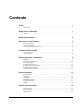
Contents Scope 1 Introduction................................................................................................................................ 1 Safety Issues / Warnings 1 Caution....................................................................................................................................... 1 Warranty Information 2 Description / Specifications 3 Printer Description.................................................................................................
Adjustments 32 Feed Roller Pressure ................................................................................................................ 32 Sensors..................................................................................................................................... 32 Sensor Adjustments: ................................................................................................................ 32 Machine Set Up Sequence ......................................................
Top - Printhead Parts List ........................................................................................................ 65 Bottom – Printhead Assembly Drawing................................................................................... 66 Bottom – Printhead Parts List .................................................................................................. 67 Ink Unwind / Rewind Assembly Drawing................................................................................
Scope Introduction This user manual was arranged for the person who is going to operate the machine. The information is arranged in the order that is needed to install and operate the machine. It starts with general information, then to unpacking the crate, installing the stock and ink ribbon, printer operation, control panel operation, and finally care and maintenance of the printer.
Warranty Information Limited Warranty AVERY DENNISON extends the following warranties to the original purchaser of a AVERY DENNISON 676LKP that has been installed and operated using recommended procedures and operating conditions. Parts Parts found defective in material or workmanship will be replaced at no charge for a period of six months following the machine's shipment date. Parts damaged by negligence, abuse, or normal wear are not covered.
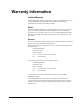
Description / Specifications Printer Description The AVERY DENNISON MODEL 676 LKP THERMAL PRINTER (Figure 1) is an electronic printer that can print on noncoated polyester stocks. The printer is available as a 2 station single sided printer, a 2 over 1- two-sided printer and as a 1 over 1 - two-sided printer. The printer interfaces to a computer or a main frame system that allows for computer input or even design of a label with AVERY DENNISON’S PCMate Plus's “FORMATTER” program.
4 • Description / Specifications User Manual Model 676 LOKPRINT®
Printer Specification Print method: Narrow web thermal transfer printer Speed – 3,4, and 5 IPS (76.2, 101.6, and 127mm/second) – w/ Lokprint II, 5” only Label Size Min: 1.062" (27mm) web x 1" (25.4mm) feed Max: 2.0" (51mm) web x 1.0" (25.4 mm) feed 2.0" (50.8mm) web x 5.0" (127 mm) feed Cutting No cutter included on printer Print Area Min: None Max: up to 2" (50.8mm) web x up to 13.875" (352.
Other Features - Downloading of information while machine is operating - Sequenced Fields - Time/Date Stamping (Both month/day/year and day/month/year format) - Life Counts - Operator adjustable: strobe, cut position, print position, baud rate, and buffer size - Error Detection of: stock out, ink out, print head open, feed open, full stacker, stacker jam, and print head over-temperature - Display: labels left to be cut and stacked in a batch, batch ID, total life inches, total life cuts - Se
Customer Responsibility Location of Printer The printer weighs approximately 250 Lbs (113.4 Kg) and requires a table of sufficient quality and strength to handle this load while the printer is operating. AVERY DENNISON recommends an industrial type worktable having the approximate dimensions of 96" (245.8cm) wide to 30" (76.2Ccm) deep to 32" (81.3cm) high. Refer to Figure 2. Figure 2 - Recommended Workstation Layout. The location of the AVERY DENNISON 676 LKP printer should be based on human factors.
The unit should always be operated with the cover closed to minimize the amount of dust and dirt in the machine.
AC Power Line AVERY DENNISON requires that the electric service be 10 Amps @ 115VAC or 10 Amps @ 230VAC. This will allow the computer and any additional support or service equipment to be plugged into the same service. Any electrical service which is supplying a AVERY DENNISON printer or peripheral equipment connected to a AVERY DENNISON printer should follow standard electrical code practices including proper grounding and neutral requirements.
Inspect the machine for shipping damage. If obvious damage is discovered, contact AVERY DENNISON for further instructions - in the U.S.A. at (570) 888-6641. In countries other than the U.S.A. please contact your local AVERY DENNISON supplier. Figure 3 - Shipping Box. Save the shipping materials to relocate the unit or return to factory for service. Inventory of Components The following list shows the additional parts (pieces) that should be included in your AVERY DENNISON 676 shipping crate.
Fuse Configuration The main fuse(s) on the AVERY DENNISON 676 LKP are located inside the AC power entry receptacle. The entry has a fuse drawer that holds the fuse(s) and selects the appropriate line voltage. If the number in the window DOES NOT match the AC line intended to be supplied to the printer, DO NOT plug the power cord in. Re configure as follows: 1) Using a flat blade screwdriver, open the AC entry by lifting the tab just above the voltage indicator window.
Installing the Power Cord A power cord is shipped with each printer. The cord for 115-volt printers will use the standard three-prong plug used in the U.S.A. A 230-volt printer and some other 115-volt configurations must have the receptacle end of the connector removed and the proper plug installed. It is the customers’ responsibility to have the plug and alteration work done by a certified electrician. AVERY DENNISON supplies printers to many countries with many variations.
Printer Operation Loading Stock TAKE-UP HEAD 2 SUPPLY HEAD 2 SUPPLY HEAD 3 TAKE-UP HEAD 3 INK FABRIC INK HEAD 2 WEB GUIDE HEAD 3 HEAD 1 DRIVE / AUX STOCK TAKE-UP HEAD 1 SUPPLY HEAD 1 Figure 4 - LOKPRINT® Threading Diagram Loading Stock For The First Time 1) Adjust the unwind width wider than the roll of stock to be loaded. Set the stock roll on the unwind between the guides with the stock unwinding from the top clockwise.
6) Open the feed rollers by rotating the feed pressure knob counterclockwise. 7) After looping the leading edge of the stock over the decurler slide it through the web guides. Keep the stock in the center, as the printer is center justified. 8) As the stock exits the web guides, continue to slide the stock through the print stations. 9) Once the stock reaches the feed rollers it maybe necessary to hold the feed pressure knob open in order to pass between the rollers.
with the outer guide contacting the roll. Turn the knob an additional ½ turn clockwise. This will activate the constant backpressure device. The second set of guides are located on the decurler just to the left of the stock registration funnel. Once a stock is loaded and tracking straight through the machine adjust this set of web guides down to the edges of the stock without deforming the stock.
Figure 5 - Print Head Open / Closed To close the head again pull the release knob and then rotate the print head into the closed latched position (see figure 5).
Installing Ink Ribbon The ink ribbon comes pre-packaged in a plastic bag. For best results, leave the ink ribbon wrapped in this bag until you are ready to use it in the printer. Use the procedure and diagram below for loading the ink.
Splices The sonic splices were dropped because they were damaging print heads and would not pull through the web guides. The new splice tape will not damage the printer, but will NOT print. The new splice may cause a sensor error on the SS Finisher. However, they will sonically cut.
Control Panel Operation Printer Controls Start - Starts the printer - ON LINE light must be GREEN (Batches downloaded to be printed) Feed - FEED and START must both be used - Feed will stop when the buttons are released - Labels between print station one and the knife will be cut and stacked as finished labels - Stock moves through in one continuous strip - Stock moves through without printing - Ink will advance, ink save on print station two will automatically be activated.
Test - TEST and START must both be used - Test will stop when the buttons are released - Labels between print station one and the knife will be cut and stacked as finished labels - Stock moves through in one continuous strip - Stock moves through with test pattern printing - The ink will advance with the stock. - The print heads must be latched in the down position. Stop - The stop button will stop the printer at the end of the current label being printed.
ORANGE - System is operational - Ready for batches to be downloaded GREEN - Batches to print, ready to start Sensor GREEN = "C" SENSOR - Printer is stopped, - light is on, - sensor is positioned over a web sensor mark - Flashing light while the printer is running, - the sensor is in-line with the registration HOLES ORANGE = REFLECTIVE SENSOR - Flashing light while the printer is running, - the sensor is in-line with the registration PRINTED MARKS Error ORANGE - System inter-lock triggered, display for err
Display Modes There are four (4) main mode levels that are selected and modified using the following function keys: Use the MODE ↓ key to move through the main mode screens shown below: Pressing the EXIT / Up arrow button will put the user at one of these two screens. HOME SCREEN R E A D Y F O R 6 7 6 / 3 0 0 / B A T C H E S L O K P R I N T I I OR B A T C H P C L 0 0 1 I D Q U A N T I T Y 1 0 Press the MODE / Down arrow button will cycle the panel through the following main screens.
SETUP SCREEN P R E S S E N T E R F O R F E A T U R E S E T U P VERIFIER SETUP SCREEN P R E S S E N T E R F O R V E R I F I E R S E T U P POWER UP DIAGNOSTICS D I A G N O S T I C T E S T 1 This screen is displayed while the Front Panel is initializing and waiting for the Thermal Control Board (TCB) response. While this screen is displayed the code will check the functionality of the LED's and the display. Each state of the LED's will be checked - (red, green, amber and off).
HOME SCREEN R E A D Y F O R 6 7 6 / 3 0 0 B A T C H E S OR B A T C H P C L 0 0 1 I D Q U A N T I T Y 1 0 When the printer is powered up and all initializations are complete, if there aren’t any Batches to print, the "HOME" screen will be "READY FOR BATCHES" and the model and print head density. When there are Batches to be printed, the "HOME" screen will be the "BATCH ID QTY" screen. The Batch ID / Batch Qty screen displays the currently cutting batch ID and labels remaining to be cut.
PRINT / CUT POSITIONS P R E S S E N T E R F O R P R I N T / C U T P O S I T I O N S This screen follows the Batch ID / Batch Qty screen if there are batches to print, otherwise it follows the “Ready for batches” / Model DPI “HOME” screen. Pressing ENTER will take the user to the PRINTER ADJUSTMENTS screens. Pressing the MODE / Down Arrow key will take the user to the "PRINTHEAD SETUP" screen. Pressing the EXIT / Up Arrow key will take the user back to the "HOME" screen.
P R I N T P O S I T I O N V A L U E : ± X X N E W S T A T I O N 3 V A L U E : ± Y Y This screen follows the second screen under PRINTER ADJUSTMENTS. This screen allows the print position of station 3 to be adjusted. The buttons are used to change the print value. The value is displayed in a positive / negative format. The value ranges for XX and YY can be from a -9 to a +9 Pressing the MODE / Down Arrow key will take the user to the next screen.
C H A N G E S T R O B E S T A T I O N 3 V A L U E : ± X X N E W V A L U E : ± Y Y This screen follows strobe adjust for station 2. This screen allows the user to adjust the strobe for station 3. The buttons are used to change the print value. The value is displayed in a positive / negative format. The value ranges for X and Y can be from a -7 to a +7. Pressing ENTER will change the CURRENT STROBE value to the NEW STROBE value.
in the machine for reasons of convenience then they can just open the head for that station and press enter. If the operating system has been changed or TCBSETUP has been used to reinitialize the machine it will show all print stations active as the default. If it is a 1/1 printer that doesn’t have station 3 installed then the user will have to come to this screen and press ‘Enter’ to deactivate station 3, otherwise the printer will show INK OUT STATION3 errors when it is run.
C O N T R O L L E R T C B 1 0 9 3 4 V E R S I O N This screen follows the FRONT PANEL VERSION screen. This screen shows operating system version for the controller (TCB). Pressing the MODE / Down Arrow key will take the user to the next screen. Pressing the EXIT / Up Arrow key will take the user back to the HOME screen. I M A G E R V E R S I O N U S A 1 9 . 0 1 This screen follows the controller version number screen. This screen shows operating system version for the imager (AT).
D E F A U L T T R A N S F E R T Y P E 1 V A L U E : X X X N E W V A L U E : Y Y Y Station 1 not used. T R A N S F E R T Y P E 2 D E F A U L T V A L U E : X X X N E W V A L U E : Y Y Y This screen follows the DEFAULT TRANSFER TYPE1 screen IF emulation mode is something other than none. This screen allows the DEFAULT TRANSFER TYPE to be changed. This transfer type is used when the printer is in 630 or 650 emulation mode for print station 2.
N E W P R O T O C O L : P R O T O C O L : X X X X X X Y Y Y Y Y Y This screen follows the LANGUAGE screen. This screen allows the communications protocol to be changed between the supported types. Use the keys to move between the supported protocols – RTS / CTS is considered hardware handshaking and XON / XOFF is considered to be software. Pressing ENTER will update the communications protocol with the selection. Pressing the MODE / Down Arrow key will take the user to the next screen.
Adjustments Feed Roller Pressure General The rubber pressure roller is supported by an eccentric shaft mounted in bearings located in vertical slots in the front and rear mounting plates of the drive module. This roller is mounted in an extension spring controlled arm so no pressure adjustment is required. Sensors Sensor Identification: Stock Out A micro switch located on the back of the unwind will detect when the stock core is lifted when the stock is consumed and stop the printer.
Feed Open If the switch is in need of adjustment - first check and adjust as needed the feed pressure as it will affect the switch adjustment. With the machine rear cover removed while opening and closing the feed pressure knob you should heard the switch clicking. If not, the switch bail is adjusted by carefully bending it as needed. Machine Set Up Sequence 1) Power off the printer, remove the media and ink and thoroughly clean it from the unwind to the stock exit using alcohol and a clean soft cloth.
Maintenance Cleaning Print Head Cleaning CAUTION: TURN OFF THE POWER TO THE PRINTER BEFORE STARTING ANY CLEANING. NEVER REMOVE THE HEAD FROM THE PRINTER EXCEPT FOR REPLACEMENT. The Anti-static wrist strap (which must contact the skin and be tight) and anti-static gloves must be worn at all times when handling a print head to avoid damaging the print head. Supplies: - Always use clean supplies when cleaning the head. - Never use anything abrasive to the head.
Clean Platen Roller You may determine if the printhead has been adjusted properly by performing a test pattern as documented elsewhere in this manual. A properly adjusted print head will produce an even grid of chevrons when the test pattern is performed. Before making any judgments as to the quality of the printhead, it is absolutely necessary to ensure that the platen roller and the printhead are clean of all debris.
Print Head Replacement NEVER REMOVE THE PRINT HEAD FROM THE PRINTER EXCEPT FOR REPLACEMENT. TURN OFF THE POWER TO THE PRINTER BEFORE STARTING ANY ELECTRONIC COMPONENT REPLACEMENT. NOTE: The Anti-static wrist strap (which must contact the skin and be tight) and anti-static gloves must be worn at all times when handling a print head to avoid damaging the print head.
7) Remove the old printhead carefully from the heat sink. HEAT SINK PRINTHEAD 8) Place the new print head onto the heat sink. 9) Replace the two print head mount screws. Be sure that the head is resting flat on the heat sink before tightening these screws. 10) Replace the print head assembly in the printer, sliding screw / washer (Paragraph 4) into the holes in the mount plate. Make sure that the screw / washer slides all the way to the front of the holder. Tighten screws.
C) Using the left () arrow key set the HEAD CATEGORY as called out in the PRINTHEAD CATEGORY CHART below. D) Press the ENTER key to enter the value. The printer must be turned off and back on for the change to take effect.
Lubrication Procedure General The 676 series printers are factory equipped with either composition bearings not requiring lubrication, pre-lubricated bronze bearings, or pre-lubricated needle bearings. Periodic cleaning of the printer and removal of dust will greatly enhance the length of the time the printer will function.
Electrical Trouble Shooting Power Up / Sign On / Communications Problem Machine fails to power up with no light present in the AC power switch. Probable Cause Corrective Action 1) Incorrect power voltage. 1) Confirm that the AC entry is configured for the line voltage intended to be applied to the machine. Failure to do so can damage the machine's internal power supply. Refer to the "Fuse Configuration". 2) Lack of power to machine. 2) Check that both ends of the power cord are plugged in securely.
Problem Probable Cause Corrective Action Front panel does not complete diagnostics test 2. 1) One or more PC board(s) unplugged from the Mother Board. 1) Power off and remove the power cord from the AC entry. Remove the back cover and reseat the offending board. Machine does not receive batches. 1) Serial communications cable loose or unconnected. 1) Check and secure both ends of the serial cable with the thumbscrews. 2) Machine not powered on or has not completed diagnostics tests.
Stock / Ink Advance Problem Stock does not advance when the start button is depressed. Ink does not advance when the start button is depressed. Probable Cause Corrective Action 1) No batches to be printed. 1) Download batch (if batch downloaded uses the same format as a previously downloaded batch the machine with start automatically). 2) An interlock condition exists. 2) Determine the number and type of interlock(s) by reading the front panel display.
Print Problem Machine advances stock but does not print. Print registration is off in the feed direction. Print registration is off in the web direction. Print contrast is too light or dark. Voids in print image in the feed direction. Machine continually stops with an erroneous interlock condition. Probable Cause Corrective Action 1) Print head cable unconnected or faulty. 1) Power off the machine and reinsert the offending connector or replace cable. 2) Print head faulty. 2) Replace print head.
Mechanical Trouble Shooting Stock Problem Stock will not roll or jumps Probable Cause 1) Incorrect adjustment of unwind web guides Corrective Action 1) Be sure stock roll is as flat as possible and does not extend over core. 2) Adjust web guides to touch stock roll but not pinch the roll. Machine fails to stop at end of roll. 1) Incorrect adjustment of stock-out sensor. 1) Adjust contact strip so that a “click” will be heard when supply roll is lifted.
Ink Problem Ink wrinkles or will not pull smoothly. Ink rolls loosely on take-up roller. Probable Cause Corrective Action 1) Ink buildup on turn bar(s). 1) Clean with alcohol. 2) Incorrect ink width. 2) Use an ink width no wider than stock being printed. This is especially critical when using a narrow web with cut down rollers. 1) Take-up roller not turning. 1) Assure roller does not bind and is clean. 2) Take-up core binding on locator plate. 2) Move core .015" - .030" (.38mm - .
Appendix A Error Messages On the Machine's detection of errors / error, the displays will show the first error encountered and allow the displaying of any other errors with the keys, which will "Scroll" through additional errors if any. XX is the total number of errors at the time of error detection.
Appendix B Software Upgrade Chip Placement Positions Thermal Control Board P/N 371105TT U 22 U 36 U 18 U3 U 4 U 23 U 19 U 20 U 21 THERMAL CONTROL BOARD Align angled corners of chip with socket and arrow denotes pin #1 or dimple on chip.
Head Driver Board P/N 371106TT U - 30 U - 10 U - 20 U-9 U-5 U-8 (Use chip removal tool p / n. 351156 for square I.C.'s) HEAD DRIVER BOARD Align angled corners of chip with socket and arrow denotes pin #1 or dimple on chip.
Front Panel Board P / N 351108 (Use chip removal tool p / n. 351156 for square I.C.'s) FRONT PANEL BOARD, Upgradeable software I.C.'s include U1. Align angled corners of chip with socket and arrow denotes pin #1 or dimple on chip.
Appendix C Printhead Life Extension NOTE: This section was written specifically for the 636 / 656 – but the information is useful and applicable for the 676 series printers. Matching stock and ink widths If your customer is running multiple media and multiple widths on their AVERY DENNISON machine, Great! They are taking advantage of one the most compelling features of our printers: multimedia capability. Our printers can also reduce the width of the ink to only that area being printed.
Printhead Fail Modes Symptoms, Causes, Solutions Symptom #1: A dot is leaving a line in the print direction. The dot appears to be dragging or failed on, sometimes in the print area, and sometimes not. If in a barcode, the verifier will halt the printer.
Printhead Cleaning Procedure Printhead performance and life are influenced by proper handling and cleaning. • • • • • Dirt on the printhead that causes problems is often too small to see. Exercise care in handling printheads, as they are very susceptible to static. Use the wrist grounding strap and anti-static gloves when handling. It is OK to scrub the printhead HARD to clean it. Use rubbing alcohol and the “loop side” or “wool side” of Velcro, followed by drying with rough, brown paper towels.
Printhead Installation and Removal Procedures Printhead removal procedure 1) Loosen (2) 6-32 Phillips screws visible through holes in the upper print head holder. Slide the head toward unwind end of printer. NOTE: Screws are fitted with washers. 2) Place your hand (with static gloves on) underneath the print line of the print head and pull down guiding screws through keyhole slots. This will remove the print head assembly from the mount plate.
Electrical Assembly Drawings Machine Wiring FEED SYSTEM HARNESS 15 PIN OUTPUT CONNECTOR FRONT PANEL VERIFIER ORANGE PH3 GRAY RED ORANGE RED BROWN (NOT USED) PH2 GRAY THERMAL CONTROL BOARD (REAR) 371105TT GRAY BROWN PH1 HEAD DRIVER BOARD (FRONT) 371106TT BROWN POWER SUPPLY 54 • Electrical Assembly Drawings User Manual Model 676 LOKPRINT®
Electrical System Schematic AC ENTRY 341111 115V 230V CONN 3 LINE LINE CORD 181134 HARNESSED +5V/+12V/+24V POWER SUPPLY 371116 POWER GOOD A L B N GROUND CONN 2 G FEED OPEN SWITCH 191120 C NEUTRAL D TOP 1 HEAD-OPEN SWITCH 375018 TOP 2 HEAD-OPEN SWITCH 375018 SEE NOTE 3 BOTTOM HEAD-OPEN SWITCH 375018 +12V 115V OPERATION ONE 10.0A 250V 1/4 X 1 1/4 FUSE 921167 OPTIONAL PCMCIA BOARD 351181 +24V +5V 230V OPERATION TWO 10.
Motherboard Power Connectors The power supply connector on any PC / XT or PC / AT compatible motherboard is made up of dual six-pin male connectors. Two female connectors from the power supply plug directly onto these male connectors. The following diagrams illustrates the proper method of attaching the connectors.
Mechanical Assembly Drawings User Manual Model 676 LOKPRINT® Mechanical Assembly Drawings • 57
Unwind Assembly Drawing 58 • Mechanical Assembly Drawings User Manual Model 676 LOKPRINT®
Unwind Parts List Item 1 2 3 4 5 6 7 8 9 10 11 12 13 14 15 16 Part # 373012 373009 373093 373010 353002 105023 373014 373013 191120 989973 990069 990000 990065 989995 371142 990513 Description Web guide, Rear Lead screw, Tape unwind Assy, Unwind pressure, LKP Rod, Web guide, Outer Bracket, Unwind Impression Adj, Knob / SS Kit Bracket, Sensor mount Bracket, Stock out Micro switch 4-40 x ½ Cap screw 8-32 Hex nut 2-56 x ¼ Cap screw 8-32 x 3/8 Button head screw 3/15 x 5/8” Shld.
Web Guide Assembly Drawing 60 • Mechanical Assembly Drawings User Manual Model 676 LOKPRINT®
Web Guide Parts List Item 1 2 3 4 5 6 7 8 9 10 11 12 13 14 Part # 374046 374113 999099 374111 374104 374103 990090 374106 374105 374101 374102 374112 999100 194013 Description Frame, Web guide Shaft, Ink turn bar 3/16 x 5/16 x ¼” Fl. Bushing R.H. Thread guide adj. Block Back (Top) Web guide Back (Bottom) Web guide 10-32 x 3/8” Button head screw Shaft, Web guide adjust Bracket, Web adjust rod Front (Bottom) Web guide Front (Top) Web guide L.H. Thread, Guide adjust block 3/16 x 5/16 x 1/8” Fl.
Drive Assembly Drawing 62 • Mechanical Assembly Drawings User Manual Model 676 LOKPRINT®
Drive Parts List Item Part # Description 1 355018 Support, Knife / Drive / Print 2 354004 Bridge blade, Lower 3 990086 10-32 x 3/8 Cap screw 4 374044 Bridge plate, Web 5 991170A Extension spring 6 514003 Pin, Spring anchor 7 514094 Lift cam assembly 8 514001 Shaft, Idler roller 9 374034 Tape roll idler, Molded 10 354094 Roller, Drive assembly 11 990325 3/16 “E” Ring 12 514009K Spring lever, Front 13 374087 Assembly, Outer drive support 14 374047 Feed knob / SS 15 990120 1/4-20 x 1/2 Cap screw 16 514010K Spr
Top - Printhead Assembly Drawing 64 • Mechanical Assembly Drawings User Manual Model 676 LOKPRINT®
Top - Printhead Parts List Item Part # Description 1 375076 Assy, Rear support, LKP 2 375077 Assy, Front support, LKP 3 375085 Support Beam, Print assembly 4 375054 Roller, 2-1/4” Cutdown (LKP) 5 356020 Roller, Molded (Ink) 6 990135 ¼-20 x ¾ Button head screw 7 990122 ¼-20 x ¾ Cap screw 8 990083 10-32 x ¾ Cap screw 9 371102 300 DPI Convex head 10 375081 Assembly, Printhead mount 11 989543 3mm x 6mm Flat head screw 12 375049 Bracket, Head mount 13 991141 6-32 x 3/8 Sems screw 14 991142 Pressure spring 15 375
Bottom – Printhead Assembly Drawing 66 • Mechanical Assembly Drawings User Manual Model 676 LOKPRINT®
Bottom – Printhead Parts List Item 1 2 3 4 5 6 7 8 9 10 11 12 13 14 15 16 17 18 19 20 21 22 23 24 25 User Manual Model 676 LOKPRINT® Part # 356020 991142 990135 375014 990497 375085 371102 375081 990058 989543 990122 375049 990328 990083 375078K 991141 376032 375054 375056 990025 990273 375080 375079 375060 990051 Description Roller, Molded (ink) Pressure spring 1/4-20 x 3/4 Button head screw Shaft, Head mount 1/2" Wave washer Support beam, Print assy 300 dpi Convex head Assy, Plate print head mount 8-32
Ink Unwind / Rewind Assembly Drawing 68 • Mechanical Assembly Drawings User Manual Model 676 LOKPRINT®
Ink Unwind / Rewind Parts List Item Part # Description 1 356201 Magnetic clutch 2 356202 Collar, Sprocket mount 3 376022 Sprocket, Altered 4 991086 6-32 x 1 1/4 Cap screw 5 991018 Internal snap ring 6 999002 Bearing 7 376025 Bearing spacer 8 376023 Bearing spacer 9 376016 Bearing housing 10 990122 1/4-20 x 3/4 Cap screw 11 356203 Shaft, Rewind 12 356016 Shaft, Foil bracket 13 376002 Ink guide 14 376003 Collar, Foil guide 15 990080 10-32 x 3/8 Cap screw 16 990313 #10 Thumb Cap 17 376096 Assembly, Arbor unwi
Web Tension Guide Assembly Drawing 11 16 2 18 15 10 7 17 6 5 8 9 12 14 3 4 70 • Mechanical Assembly Drawings 7 User Manual Model 676 LOKPRINT® 1
Web Tension Guide Parts List Item 1 2 3 4 5 6 7 8 9 10 11 12 13 14 15 16 17 18 User Manual Model 676 LOKPRINT® Part # 191120 564088 564087 564089 990374 990484 194020 989973 563006 990050 563001 564097 561165 999099 990416 990056 990120 990058 Description Stock out micro switch Bracket, Roller Shaft, Support Shaft, Roller 1/2 Collar 1/4-20 x 1/2 Nylon slotted screw Web turn shaft 4-40 x 1/2" Socket hd cap screw Bracket, Sensor 8-32 x 1/4" Socket hd cap screw Bracket, Guide mount Bracket, Bridge blade Har
Drive Belt Routing Drawing 374006 - "LONG BELT" DOUBLE SIDED 991143 - "SHORT BELT" SINGLE SIDED 72 • Mechanical Assembly Drawings User Manual Model 676 LOKPRINT®
User Manual Model 676 LOKPRINT® Mechanical Assembly Drawings • 73