Third-Generation Mbox Technology Guide
Table of Contents Design Philosophy Behind the Third-Generation Mbox Family......................................................3 The Elements of a Great Audio Interface.......................................................................................3 Converters..................................................................................................................................3 Preamps........................................................................................................
Design Philosophy Behind the Third-Generation Mbox Family In designing the new Avid® Mbox® family of audio interfaces, our industry-leading engineering team set out to create best-in-class products that would surpass their previous efforts in this category—as well as those of other manufacturers. To meet this goal, we leveraged technology from our top-of-the-line Pro Tools|HD recording systems, and also drew from our extensive experience developing mobile recording solutions.
The Keys to the Mbox Sound Listening Tests Before commencing work, our design team engaged in a series of listening tests. We sampled Avid interfaces as well as products from other manufacturers, then worked to develop the clearest, most transparent-sounding interfaces possible. With each subsequent revision of the electronics, our team reconvened for another set of exhaustive listening tests to ensure exceptional performance.
Expertise Our engineering team relied on their personal experience as musicians and audiophiles to ensure that the Mbox interfaces would yield pleasing, musical results in even the most demanding circumstances. For example, if pushed to the point of distortion when capturing heavy vocals, the distortion sounds musical rather than harsh. These audible performance characteristics further separate Mbox from products by other manufacturers.
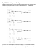
Signal Path, Internal Layout, and Routing In addition to selecting premium components and creating the shortest possible signal path between them, our engineers worked to optimize each model’s signal chain for its intended use, as detailed below. Mbox Pro Signal Path The Mbox Pro audio interface features 8 x 8 simultaneous channels of I/O. There are four microphone inputs with 48V phantom power (two XLR/DI combo, two XLR), plus four 1/4” TRS line inputs.
Microphone Input The signal goes from the XLR input into a premium-quality preamp with a pad, which provides over 74 dB of gain range (including the 20 dB pad). From there, the signal goes to a high-pass filter, which is controlled by software via a high-quality relay. Then the signal passes to an insert jack on the back of the interface, so the user can send to external devices, and the return will come in through the same insert.
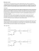
The Mbox interface provides 4 x 4 simultaneous channels of I/O—two XLR mic/line combo inputs with 48V phantom power, and two 1/4” DI inputs on the front panel for easy access. The Mbox signal path is designed to offer optimum flexibility for mobile scenarios and field use. The line inputs pass through the preamps, so users can plug in a variety of sources and just tweak the gain as needed.
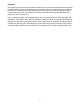
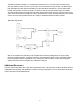
Appendix As with all Avid product specifications, the published Mbox specs reflect actual performance measurements. Mbox Family Specification Comparison Mbox Pro Mbox Mbox Mini +/-0.1 dB 112 dB -112 dB -100 dB -120 dB +14 dBu / +6 dBV (switched) 10 k (20 k) +/-0.1 dB 110 dB -110 dB -100 dB -120 dB +/-0.1 dB 106 dB -106 dB -94 dB -116 dB +4.2 dBu +0 dBu 10 k (20 k) 10 k (20 k) Min Gain, No Pad +/-0.1 dB 110 dB -110 dB -100 dB -128 dB -120 dB +0.5 dBu +20.5 dBu 1.8 k (3.
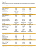
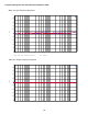
1 2 Red Solid 3 DSP Anlr.Level B Left Line Outputs, -10dBu @1kHz Output Freq Resp.at27 Frequency Response and Total Harmonic Distortion (THD) Mbox Pro Input Frequency Response AVID Mbox Pro +1 +0.8 +0.6 +0.4 +0.2 d B r +0 1 -0.2 -0.4 -0.6 -0.8 -1 20 20k 50 100 200 500 1k 2k 5k 10k 20k 1k 2k 5k 10k 20k Hz Sweep Trace Color Line Style Thick Data Axis 1 1 1 2 Blue Red Solid Solid 3 3 DSP Anlr.Level A DSP Anlr.
1 2 Red Solid 3 Fft.Ch.2 Ampl Left 1 THD (-1dBFS signal) FFT, Line Outputs L Output THD FFT.at27 Mbox Pro Input THD AVID AVID Mbox Pro +0 +1 -10 +0.8 -20 -30 +0.6 -40 +0.4 -50 -60 +0.2 -70 d B F S -80 d B r -90 1 +0 -0.2 -100 -110 -0.4 -120 -0.6 -130 -140 -0.8 -150 -160 20 50 100 200 500 1k 2k 5k 10k -1 20 20k Hz Sweep Trace Color Line Style Thick Data Axis 1 1 1 2 Blue Red Solid Solid 3 3 Fft.Ch.1 Ampl Fft.Ch.
1 2 Red Solid 3 Fft.Ch.2 Ampl 1 Left L THD (-1dBFS signal) FFT, Line Outputs Output THD FFT.at27 Mbox Input Frequency Response AVID Mbox AVID +0 +1 -10 +0.8 -20 -30 +0.6 -40 +0.4 -50 -60 +0.2 d B r d B F S +0 1 -0.2 -70 -80 -90 -100 -110 -0.4 -120 -0.6 -130 -140 -0.8 -150 -1 20 50 100 200 500 1k 2k 5k 10k 20k -160 20 Hz Sweep Trace Color Line Style Thick Data Axis 1 1 1 2 Blue Red Solid Solid 3 3 DSP Anlr.Level A DSP Anlr.
1 2 Red Solid 3 DSP Anlr.Level B Left Line Outputs, -10dBu @1kHz Output Freq Resp.at27 Mbox Input THD AVID Mbox +0 -10 -20 -30 -40 -50 -60 -70 d B F S -80 -90 -100 -110 -120 -130 -140 -150 -160 20 20k 50 100 200 500 1k 2k 5k 10k 20k Hz Sweep Trace Color Line Style Thick Data Axis 1 1 1 2 Blue Red Solid Solid 3 3 Fft.Ch.1 Ampl Fft.Ch.2 Ampl Left Left Mbox Output THD AVID Comment AVID Mbox THD (-1dBFS signal) FFT, Mic Inputs, Min Gain THD FFT.at27 -9 +10 +0 -9.
1 2 Red Solid 3 Fft.Ch.2 Ampl Left 1 THD (-1dBFS signal) FFT, Line Outputs L Output THD FFT.at27 Mbox Mini Input Frequency Response AVID Mbox Mini AVID +1 +0 -10 +0.8 -20 -30 +0.6 -40 +0.4 -50 -60 +0.2 d B r d B F S +0 1 -0.2 -70 -80 -90 -100 -110 -0.4 -120 -0.6 -130 -140 -0.8 -150 -1 20 50 100 200 500 1k 2k 5k 10k 20k -160 20 Hz Sweep Trace Color Line Style Thick Data Axis 1 1 1 2 Blue Red Solid Solid 3 3 DSP Anlr.Level A DSP Anlr.
1 2 Red Solid 3 DSP Anlr.Level B Left Line Outputs, -10dBu @1kHz Output Freq Resp.at27 Mbox Mini Input THD AVID Mbox Mini +0 -10 -20 -30 -40 -50 -60 -70 d B F S -80 -90 -100 -110 -120 -130 -140 -150 -160 20 20k 50 100 200 500 1k 2k 5k 10k 20k Hz Sweep Trace Color Line Style Thick Data Axis 1 1 1 2 Blue Red Solid Solid 3 3 Fft.Ch.1 Ampl Fft.Ch.2 Ampl Left Left Mbox Mini Output THD AVID Comment AVID Mbox Mini THD (-1dBFS signal) FFT, Line Inputs, Min Gain THD FFT.