Avid NewsCutter ® ® Site Preparation Guide Release 2.
Copyright and Disclaimer Product specifications are subject to change without notice and do not represent a commitment on the part of Avid Technology, Inc. The software described in this document is furnished under a license agreement. The software may not be reverse assembled and may be used or copied only in accordance with the terms of the license agreement. It is against the law to copy the software on any medium except as specifically allowed in the license agreement.
The following notice is required by Altura Software, Inc. for the use of its Mac2Win software and Sample Source Code: ©1993–1998 Altura Software, Inc. The following notice is required by Ultimatte Corporation: Certain real-time compositing capabilities are provided under a license of such technology from Ultimatte Corporation and are subject to copyright protection. Attn. Government User(s). Restricted Rights Legend U.S. GOVERNMENT RESTRICTED RIGHTS.
Contents Using This Guide About This Guide. . . . . . . . . . . . . . . . . . . . . . . . . . . . . . . . . . . . . . . . . . . . 7 Symbols and Conventions . . . . . . . . . . . . . . . . . . . . . . . . . . . . . . . . . . . . 8 If You Need Help . . . . . . . . . . . . . . . . . . . . . . . . . . . . . . . . . . . . . . . . . . . . 8 Related Information. . . . . . . . . . . . . . . . . . . . . . . . . . . . . . . . . . . . . . . . . . 9 If You Have Documentation Comments . . . . . . . . . . . . . . . . . .
Fiber-Optic Switch. . . . . . . . . . . . . . . . . . . . . . . . . . . . . . . . . . . 33 Ethernet Hub. . . . . . . . . . . . . . . . . . . . . . . . . . . . . . . . . . . . . . . . 34 Patch Panel . . . . . . . . . . . . . . . . . . . . . . . . . . . . . . . . . . . . . . . . . 34 Pin Assignments . . . . . . . . . . . . . . . . . . . . . . . . . . . . . . . . . . . . . . . . . . . . 34 Serial Ports . . . . . . . . . . . . . . . . . . . . . . . . . . . . . . . . . . . . . . . . . . . . .
Using This Guide This guide provides site requirement information for the Avid® NewsCutter® system. About This Guide The guide provides specifications for your Avid system components in the following areas: • Connectors • Environmental • Physical (dimensions and weight) • Electrical Use this guide if you are responsible for preparing a site for installation.
Symbols and Conventions This guide uses the following special symbols and conventions: 1. Numbered lists, when the order of the items is important. a. • Alphabetical lists, when the order of secondary items is important. Bulleted lists, when the order of the items is unimportant. n A note provides important related information, reminders, recommendations, and strong suggestions. c A caution means that a specific action you take could cause harm to your computer or cause you to lose data.
4. For customer support, contact your local Avid Reseller, or contact Avid Customer Support directly: • Broadcast customers — call 800-NEWS-DNG (639-7364). • Postproduction customers — call 800-800-AVID (2843).
• Avid NewsCutter Release Notes This document describes new features, hardware and software requirements, software installation instructions, and summary information on system and memory requirements. • Avid NewsCutter Upgrade Instructions This document explains how to upgrade the hardware and software in NewsCutter systems in accordance with the latest feature and performance enhancements.
How to Order Documentation To order additional copies of this documentation from within the United States, call Avid Telesales at 800-949-AVID (2843). If you are placing an order from outside the United States, contact your local Avid representative.
Avid NewsCutter Site Preparation This guide provides information about requirements for the site where the Avid NewsCutter system will be installed. Electrical and physical specifications on the system components are also included. Connector information and pin assignments are given if customized cabling is required. Avid System Layouts This section provides typical system layouts. Diagrams of the Avid system components identify the rear interface connectors.
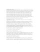
NewsCutter Layout Figure 1 shows all standard and optional NewsCutter components except for a video reference source (such as a black burst generator). Set up your system components, especially the User Interface (UI) and Playback monitors, video deck, and keyboard, in positions that give you easy access to them. V-LAN VLXi Video deck Playback monitor Speaker UI monitor Amplifier Industry-standard rack (optional) Speaker VLX O AUDIO SYNC PULL DOWN 48 kHz VIDEO SYNC POWER l 44.
• Ethernet network interface; required for Avid network connections. • High-resolution monitor (1024 x 768); required for viewing the media edits. • Windows NT® Workstation Version 4.0 operating system with Windows NT service pack. Avid Unity for News Workgroup Layout NewsCutter can work as a standalone system or as part of a broadcast network such as an Avid Unity™ for News workgroup.
n An optional Fibre Channel connection kit is available for connecting NewsCutter to the Avid Unity MediaNet environment. • An Ethernet network that is used as a general-purpose communications network connecting all the system components. An Ethernet network can also be used by the TransferManager server to transfer media files between workgroups. The purpose of the workgroup is to enable collaborative workflows by allowing multiple NewsCutter editors to share media files and other project data.
Playback device Still store Character generator Serial connections to playback devices NewsCutter systems (see Figure 1 for a typical layout) Broadcast Control System Fibre Channel switch l O l O l O Local network hub or switch Avid Unity TransferManager server to another workgroup MediaManager server Figure 2 n MediaNet file server and Avid Unity storage Sample Layout for an Avid Unity for News Workgroup Environment For information about setting up NewsCutter in an Avid Unity for News work
Fibre Channel Workgroup Configuration An optional Fibre Channel connection kit is available for NewsCutter. If you are installing a Fibre Channel connection kit, follow the instructions provided by the computer manufacturer for removing the cover and installing an expansion board in NewsCutter. NewsCutter Connectors The NewsCutter system is a computer with specific peripheral boards installed for converting the incoming video and audio, analog or digital signals into digital format for storage.
Table 1 Connector Name Connector NewsCutter Connector Identifiers Function Digital media board (M port) Interface between NewsCutter and the Avid Meridien™ I/O box (Avid proprietary cable, shipped with NewsCutter) VGA VGA output from standard VGA board, 15-pin DB-connector; connects to VGA interconnect cable Network Network interface, RJ-45 network jack SCSI SCSI port, fast and wide interface, 68-pin female DB-connector; connects MediaDrives PS/2-style Two PS/2-style connectors (keyboard and mou
Avid Meridien I/O Box Connectors The Avid Meridien I/O box provides all the audio and video input and output connections for the NewsCutter system (including four-channel audio with the second audio interface installed). Figure 3 identifies the audio connectors. See Table 2 for a description of each connector.
Table 2 Number Meridien I/O Box Audio Identifiers (Continued) Label Function 4 AUDIO OUT CHAN 1 Channel 1 audio output, male connector 5 AUDIO OUT CHAN 2 Channel 2 audio output, male connector 6 AES/EBU IN AES/EBU digital input, female connector 7 AES/EBU OUT AES/EBU digital output, male connector 8 S/PDIF IN S/PDIF digital input, phono (RCA) jack 9 S/PDIF OUT S/PDIF digital output, phono (RCA) jack 10a AUDIO IN MIC2 Microphone audio input 2, female connector 11 AUDIO IN CHAN 3 Ch
Figure 4 identifies the video connectors on the Meridien I/O box. See Table 3 for a description of each connector. 1 17 Number 3 5 2 4 6 16 14 12 15 13 7 10 11 8 9 Figure 4 Meridien I/O Box Video Connectors Table 3 Meridien I/O Box Video Identifiers Label Function 1 COMPONENT Y IN Video Y component input, BNC connector. Connects to analog video output of decks, satellite feeds, or routers. 2 COMPONENT R-Y IN Video R-Y component input, BNC connector.
Table 3 Number Meridien I/O Box Video Identifiers (Continued) Label Function 5 COMPONENT R-Y OUT Video R-Y component output, BNC connector. Connects to analog video input of decks or routers. 6 COMPONENT B-Y OUT Video B-Y component output, BNC connector. Connects to analog video input of decks or routers. 7 SYSTEM IN/OUT Audio and video I/O connector from NewsCutter. 8 LTC OUT Longitudinal timecode (LTC) output, male connector (timecode output currently is not functional).
Table 3 Number 17 Meridien I/O Box Video Identifiers (Continued) Label Function Video Reference (REF) Black burst input, BNC connector. Synchronizes decks and V-LAN® VLXi® controller that are part of the system. Figure 5 identifies the optional serial digital connectors on the Meridien I/O box. See Table 4 for a description of each connector. n Instructions for installing the optional serial digital board are provided in the Avid NewsCutter Setup Guide.
Table 4 Number Meridien I/O Box Serial Digital Identifiers Label Function 1 SERIAL DIGITAL IN Composite video input, BNC connector. Connects to digital video output of decks, satellite feeds, or routers. 2 SERIAL DIGITAL OUT 1 Composite video output, BNC connector. Connects to digital video input of decks, monitors, or routers. 3 SERIAL DIGITAL OUT 2 Composite video output, BNC connector. Connects to digital video input of decks, monitors, or routers.
Table 5 System Cable Lengths Cable Standard Length Maximum Length Connects Power cables 6 ft (1.8 m) Included with system components A quality power strip can be used (not supplied). NewsCutter and system components to ac source (or power strip) Keyboard cable 6 ft (1.8 m) Attached to keyboard Up to 12 ft (3.6 m) A quality PS/2 extender cable can be used (not supplied). Keyboard to NewsCutter Mouse cable 6 ft (1.8 m) Attached to mouse Up to 12 ft (3.
Table 5 System Cable Lengths (Continued) Cable Standard Length Maximum Length Connects Fiber-optic cable (optional) Customer supplied 50 micron, up to 1650 ft (500 m) NewsCutter clients and playback devices to Fibre Channel hub (Fiber-optic cables must be industry certified.) 65 micron, up to 577.5 ft (175 m) Remote-control serial cable 12 ft (3.
Component Weights and Dimensions Table 6 provides the dimensions and weights of Avid system components. Table 6 Component Physical Specifications for Components Rack- Rack mount Units Height x Width x Depth Weight Meridien I/O box Yes (Includes a two-channel audio interface and video interface. The serial digital interface is optional.) 3 5.21 x 17.25 x 7.6 in (13.2 x 43.9 x 19.3 cm) 15.5 lb (7 kg) Yes NewsCutter (IBM® IntelliStation® Z Pro Type 6866 system) 4 17.3 x 8.5 x 23.9 in (44.0 cm x 21.
Table 6 Component Physical Specifications for Components (Continued) Rack- Rack mount Units Height x Width x Depth Weight External Drives MediaDrive rS LVD (with Yes interlocking stacking brackets) 2 3.1 x 8.2 x 9.9 in (7.9 x 20.8 x 25 cm) 7.1 lb (3.2 kg) MediaDock LVD rack mount Yes (includes a maximum of eight MediaDock Shuttle™ drives and two power supplies) 4 + 1 for cables 5.3 x 17.6 x 16.3 in (13.3 x 44.6 x 41.4 cm) 63 lb (28.
Site Requirements The following are the site requirements for NewsCutter. Power Requirements Avid strongly recommends using a surge protector and an uninterruptible power supply (UPS). If the computer loses power even for a moment, the entire system will stop functioning. There must be a 20 A, 110 to 120 V alternating current (ac), 60 Hz or 10 A, 220 to 224 V ac, 50 Hz circuit for each NewsCutter. The circuit must have a dedicated circuit breaker and an isolated ground.
Table 7 Power Requirements Item Type Voltage Frequency Power Meridien I/O box Auto-sensing 100 to 120 V ac 220 to 240 V ac 60 Hz 50 Hz 65 W NewsCutter (IBM IntelliStation Z Pro Type 6866 system) Auto-sensing 90 to 137 V ac 180 to 265 V ac 47 to 63 Hz Minimum, 0.
Table 7 Item Power Requirements (Continued) Type Voltage Frequency Power 21-inch UI monitor Auto-sensing 100 to 120 V ac 200 to 240 V ac 60 Hz 50 Hz 150 W 17-inch UI monitor Auto-sensing 100 to 120 V ac 200 to 240 V ac 60 Hz 50 Hz 120 W Playback monitor (user supplied; requirements vary) — — — — GPI controller Auto-sensing 90 to 240 V ac 47 to 63 Hz 30 W Black burst generator Switch selectable 120 V ac 240 V ac 60 Hz 50 Hz 20 W V-LAN and VLXi Auto-sensing 120 V ac 220 V ac 6
Printing Requirements NewsCutter uses standard 25-pin parallel printing capabilities. The parallel port is AT-compatible, supporting bidirectional, EPP, and ECP protocols. You can use network printers via Ethernet connections. Telephone Requirements Systems do not include a modem. Communication outside the NewsCutter system should be done through the network board. A telephone near the system is recommended if you need to communicate with your Avid representative.
Table 8 Environmental Specifications Condition Range Operating temperature 50°F to 75°F (10°C to 24°C) Storage temperature –4°F to 140°F (–20°C to 60°C) Relative humidity 20% to 80% Altitude 0 to 6000 ft (0 to 1829 m) Networking Requirements NewsCutter is designed to work over industry-standard local area networks (LANs) and wide area networks (WANs), using standard networking protocols. NewsCutter systems include an RJ-45 Ethernet network connector.
Ethernet Hub The Ethernet hub connects NewsCutter clients to Avid broadcast network segments. Ethernet hubs have multiple RJ-45 ports that connect all the network devices. When a packet arrives at one port, it is copied to all the other ports so that all segments of the LAN can see all packets. A 100BASE-T Ethernet hub is required when connecting within a production workgroup. Typically, status LEDs on the hub show valid connections or network activity.
Serial Ports NewsCutter has two serial ports (COM1 and COM2). The ports can be internally configured to communicate in RS-232 and RS-422 protocol. The NewsCutter serial ports use 9-pin male connectors. Figure 6 shows the connector pinouts. 1 5 6 Figure 6 5 9 7 1 6 9-Pin Serial Connector Table 9 lists the pin assignments for the serial connectors. Not all serial devices use every signal.
Table 9 Serial Connector Pin Assignments (Continued) Pin RS-232 Signal RS-422 Signal 8 Clear to send Receive data – 9 Ring indicator Ground VGA Monitor Port The UI Monitor port uses a 15-pin female VGA connector. Figure 7 shows the pinouts for the connector. 5 1 10 6 15 Figure 7 11 VGA Monitor Connector Table 10 lists the pin assignments for the VGA UI monitor connector.
Table 10 VGA Connector Pin Assignments (Continued) Pin Signal 5 Display Data Channel GND 6 Red GND 7 Green GND 8 Blue GND 9 Not used 10 SYNC GND 11 GND 12 Serial Data 13 Horizontal SYNC 14 Vertical SYNC 15 Serial Clock Keyboard and Mouse Connectors NewsCutter provides two PS/2-style connectors used for the keyboard and mouse. Figure 8 shows the pinouts for these 6-pin female connectors.
Table 11 lists the PS/2-style connector pin assignments. Table 11 PS/2 Connector Pin Assignments Keyboard/Mouse Pin Signal 1 Data 2 NC 3 Ground 4 +5 volts 5 Clock 6 NC NC – no connection RJ-45 Jacks Category 5 UTP cable supports up to 1 gigabit per second (1000 megabits per second). The cable contains four twisted pairs of wires, for a total of eight wires. Avid recommends using Category 5 cables for serial connections whenever possible.
The standard pin configuration for an 8-pin RJ-45 jack (used on Category 5 cables) is shown in Figure 9. 1 Figure 9 8 Category 5, RJ-45 Connector Table 12 lists the pin assignments with color code according to the IEEE specification for an EIA/TIA-568B RJ-45 wiring scheme. Not all devices use every pin. Pairs are identified by colors. Ethernet 100BASE-T data connections use only the orange (pins 1 and 2) and green pairs (pins 3 and 6).
GPI Connector The Videomedia® VLXi-GT GPI controller contains six programmable general-purpose interface (GPI) inputs/outputs with quick-disconnect terminal connectors. Each connector contains three terminals: the left terminal is the GPI input, the center terminal is the GPI ground, and the right terminal is the GPI output. Remove about 1/4-inch of insulation from the appropriate wire and insert the bare wire into the appropriate terminal.
Regulatory and Safety Notices FCC Notice This device complies with Part 15 of the FCC Rules. Operation is subject to the following two conditions: 1. This device may not cause harmful interference. 2. This device must accept any interference received, including interference that may cause undesired operation. This equipment has been tested and found to comply with the limits for a Class A digital device, pursuant to Part 15 of the FCC Rules.
Canadian ICES-003 This Class A digital apparatus meets all requirements of the Canadian Interference Causing Equipment Regulations. Cet appareil numérique de la classe A respecte toutes les exigences du Règlement sur le matériel brouilleur du Canada. European Union Notice Declaration of Conformity (According to ISO/IEC Guide 22 and EN 45014) Application of Council 73/23/EEC, 89/336/EEC.
Product Name: Products for the Windows NT Operating System: Media Composer, Film Composer, Avid Xpress, Avid Xpress DV, Avid Unity, Avid|DS, NewsCutter, NewsCutter XP, NewsCutter DV, Symphony Products for the Macintosh Operating System: Media Composer, Film Composer, Avid Xpress, Avid Unity Base Model Numbers: None Product Options: All Year of Manufacture: 2000 (1) Products for the Windows NT Operating System: products were tested in a typical Media Composer, Film Composer, Avid Xpress, Avid Xpress
Australia and New Zealand EMC Regulations N1709 John Kells, Australian Operations Manager Avid Technology (Australia) 166 Epping Road Lane Cove N.S.W.