Avid Unity ISIS System ™ Setup Guide December.
Copyright and Disclaimer Product specifications are subject to change without notice and do not represent a commitment on the part of Avid Technology, Inc. The software described in this document is furnished under a license agreement. You can obtain a copy of that license by visiting Avid's Web site at www.avid.com. The terms of that license are also available in the product in the same directory as the software.
Attn. Government User(s). Restricted Rights Legend U.S. GOVERNMENT RESTRICTED RIGHTS. This Software and its documentation are “commercial computer software” or “commercial computer software documentation.” In the event that such Software or documentation is acquired by or on behalf of a unit or agency of the U.S. Government, all rights with respect to this Software and documentation are subject to the terms of the License Agreement, pursuant to FAR §12.212(a) and/or DFARS §227.7202-1(a), as applicable.
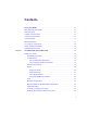
Contents Using This Guide . . . . . . . . . . . . . . . . . . . . . . . . . . . . . . . . . . . . . . . . . . . . 11 Who Should Use This Guide. . . . . . . . . . . . . . . . . . . . . . . . . . . . . . . . . . . . . . . . . . . 11 About This Guide . . . . . . . . . . . . . . . . . . . . . . . . . . . . . . . . . . . . . . . . . . . . . . . . . . . 11 Symbols and Conventions . . . . . . . . . . . . . . . . . . . . . . . . . . . . . . . . . . . . . . . . . . . . 11 Symbols and Conventions . . . . . . . . . .
Chapter 2 Connecting the Equipment . . . . . . . . . . . . . . . . . . . . . . . . . . . . . . . . . . . . 30 Connecting Power to Equipment . . . . . . . . . . . . . . . . . . . . . . . . . . . . . . . . . . . . . . . 30 Three 20-Amp AC Circuits for Three Engines . . . . . . . . . . . . . . . . . . . . . . . . . . 31 Three 20-Amp AC Circuits for Two Engines . . . . . . . . . . . . . . . . . . . . . . . . . . . 32 Two 20-Amp AC Circuits for Two Engines . . . . . . . . . . . . . . . . . . . . . . . . . . . .
Chapter 4 Avid Unity ISIS LED Status . . . . . . . . . . . . . . . . . . . . . . . . . . . . . . . . . . . . 67 LED Locations and Colors . . . . . . . . . . . . . . . . . . . . . . . . . . . . . . . . . . . . . . . . . . . . 67 Interpreting LED Error Reporting . . . . . . . . . . . . . . . . . . . . . . . . . . . . . . . . . . . . . . . 68 Interpreting Software Installation LED Reporting . . . . . . . . . . . . . . . . . . . . . . . . . . . 68 LED Summaries . . . . . . . . . . . . . . . . . . . . . . . . .
Illustrations Basic Avid Unity ISIS Media Network Hardware . . . . . . . . . . . . . . . . . . . . . . . . . . . . 17 System Director Front View . . . . . . . . . . . . . . . . . . . . . . . . . . . . . . . . . . . . . . . . . . . . 18 Engine Front View . . . . . . . . . . . . . . . . . . . . . . . . . . . . . . . . . . . . . . . . . . . . . . . . . . . 20 Engine Rear View. . . . . . . . . . . . . . . . . . . . . . . . . . . . . . . . . . . . . . . . . . . . . . . . . . . . 21 ISS Connections. . . . . . . .
Tables Product Nomenclature . . . . . . . . . . . . . . . . . . . . . . . . . . . . . . . . . . . . . . . . . . . . . . . 16 System Director Control Panel . . . . . . . . . . . . . . . . . . . . . . . . . . . . . . . . . . . . . . . . . 19 Supported Cables . . . . . . . . . . . . . . . . . . . . . . . . . . . . . . . . . . . . . . . . . . . . . . . . . . . 27 Install Products Dialog Box Buttons . . . . . . . . . . . . . . . . . . . . . . . . . . . . . . . . . . . . . 58 Software Installation LED Reporting .
Using This Guide Congratulations on your purchase of an Avid Unity ISIS™ system. You can use your system to store broadcast-quality output incorporating every possible production element from fullspeed, high-resolution footage to multimedia artwork and animation, to computer-generated effects and titling. n The documentation describes the features and hardware of all models. Therefore, your system might not contain certain features and hardware that are covered in the documentation.
Using This Guide n The documentation describes the features and hardware of all models. Therefore, your system might not contain certain features and hardware that are covered in the documentation. Symbols and Conventions Avid documentation uses the following symbols and conventions: Symbol or Convention Meaning or Action n A note provides important related information, reminders, recommendations, and strong suggestions.
If You Need Help If You Need Help If you are having trouble using Avid Unity ISIS: 1. Retry the action, carefully following the instructions given for that task in this guide. It is especially important to check each step of your workflow. 2. Check for the latest information that might have become available after the documentation was published: - If the latest information for your Avid® product is provided as printed release notes, they ship with your application and are also available online.
Using This Guide Accessing the Online Library The Avid Unity ISIS Online Library DVD contains all the product documentation in PDF format. You can access the library from the Online Library DVD. n You will need Adobe® Reader® to view the documentation online. You can download the latest version from the Adobe web site. To access the online library from the Online Library CD-ROM: 1. Insert the Online Library CD-ROM into the drive. 2. Double-click the Mainmenu file.
Chapter 1 Avid Unity ISIS System Overview This chapter provides an overview of an Avid Unity ISIS™ (Infinitely Scalable Intelligent Storage) system and the basic function of each Avid hardware component within the system. This guide describes how to connect cables between components that create a basic system and then how to connect more than one basic system together to create a larger, redundant system.
Chapter 1 Avid Unity ISIS System Overview Hardware Overview The components of a basic system enables multiple clients to capture, play, and edit video and audio media. The components have specific Avid names that define their function. The Naming Convention While you are reading this manual it is important to understand the terms used while explaining the installation of the system.
Hardware Overview Basic Avid Unity ISIS Media Network Hardware Front view Rear view Power supply ISIS Integrated Expansion switch (IXS) Avid unity ISIS Storage Blade ISB ISIS Integrated Switch (ISS) Engine System Director front view Although there are many pieces of equipment are needed to create, connect, and use an Avid Unity ISIS media network, the major components needed to create the system are a System Director, an engine containing ISIS Integrated Switch (ISS), ISIS Expansion Switch (IXS), ISIS
Chapter 1 Avid Unity ISIS System Overview System Director The System Director is 2U in size (see “System Director Front View” on page 18) and manages the metadata by storing directory information and file attributes. The System Director does not store actual data, that is stored on the ISBs within the engine. n n n The System Director password is preset to is-admin. You can have two System Directors configured in a redundant configuration, one Active the other Standby.
Hardware Overview The following table describes the control panel shown in the previous figure. l System Director Control Panel A Power/Sleep button G System ID LED B NIC 2 activity light H System ID button C NIC 1 activity light I System reset button D Power/Sleep LED J USB 2.
Chapter 1 Avid Unity ISIS System Overview Engine The major function of the engine, with all internal components installed, is to store the data created during actions performed by clients that are sent through the switches. The engine contains: • 16 ISBs, each with 500 GB of storage available in two 250-GB drives. This provides you with 8 terabyte (TB) of storage per engine. As technology advances, the size of the disks could increase, allowing the total storage per ISB/engine to increase.
Hardware Overview Engine Rear View The following figure shows the rear of the engine in a configuration that contains the following: n • Three power supplies (with fans) • Integrated Switch blade (ISS) • Integrated Expansion Switch Blade (IXS) In a basic configuration containing two engines, each of the engines contains two ISS modules. The IXS module is used with an ISS module in an engine only when the configuration goes beyond two engines.
Chapter 1 Avid Unity ISIS System Overview Two Integrated Ethernet Switches The two integrated Ethernet switches, ISS and IXS, serve different purposes and contain different types of connections. You must have at least two switches in each engine for the system to operate. ISS Module The connections on the ISS module are used for the following: w • Management connection — used to configure the Avid Unity ISIS engine hardware during installation.
Hardware Overview IXS Module The IXS is needed only if you are connecting three or more engines. It is used in the engine with an ISS module. The connections on the IXS module are used for the following: • Management connection — used to configure the switch during installation and monitor switch functions. • High speed engine interconnect — proprietary Avid interconnection that stacks the switches to create one large virtual switch.
Chapter 1 Avid Unity ISIS System Overview Maximum Configurations The maximum number of clients and the maximum amount of storage available at this time are: n • The maximum number of connections are (other than an System Director and engine) is 100. This is normally looked at as the maximum number of clients, including Avid AirSpeed devices, being 100. • A fully populated Avid Unity ISIS system can contain 64 terabytes of storage connected to two subnets.
Hardware Overview ZONE 2 Avid Unity ISIS Media Network Configuration Client Client VLAN 2 Client Client Client VLAN 1 Switch with 2 10-Gb Ports System Director Two 10-Gb Ports ISS ISS Engine A mixed configuration (Zone 1 and Zone 2) of clients consists of group of clients connected directly and indirectly to an engine through a switch blade. Also shown are two System Directors that connect to the engine via two separate ISS 1-Gb ports for use as a redundant System Director in case of a failure.
Chapter 1 Avid Unity ISIS System Overview A ZONE 3 (indirect connect) configuration consists of group of clients normally connected to an Edge access Ethernet switch. This switch is normally connected to a core switch that has uplinks that connect to the Avid Network through an Ethernet switch that contains a 10-Gb port connected to an ISS located in the engine. The System Director also connects to the both subnets via both ISS modules using a 1-Gb port.
Hardware Overview Supported Cabling Avid supports the following cable types for connecting a Avid ISIS system. Supported Cables Cable Name Function Avid engine Interconnect CX-4 cable. Only available from Avid. Connect engines. See Avid 3 supported lengths at this time: Engine CX-4 Interconnect Cable 1, 3 and 5 meters for proper removal. RJ45 Cat 5E or Cat 6 Connect management port to Ethernet cable (minimum).
Chapter 1 Avid Unity ISIS System Overview Connecting the Engine CX-4 Cable Connecting the engine CX-4 interconnect cable to the connector at the rear of the system is straight forward. To connect the cable: t Place it in the connector at the rear of the system. You hear a snap, and the cable is connected. Avid Engine CX-4 Interconnect Cable Cable disconnect c n Damage can occur when disconnecting the Avid engine Interconnect cable from the switch board if not done properly.
Hardware Overview Pull back on blue cable release Push cable or metal towards engine 3. Pull back with both hands to remove the cable.
Chapter 2 Connecting the Equipment This chapter explains how to rackmount and connect the system hardware. To do this, a system installation check list is provided to help you perform the installation in the correct order. The installation check list continues past the information in this chapter and points you to the correct area in this document or the ReadMe file to continue the installation.
Connecting Power to Equipment n c Do not actually connect the power cords to the engines until told to do so in chapter 3. Use this section to determine how you should connect power to the engines. Place the power cords into the engines when you place them into the rack as explained in “RackMounting the Equipment” on page 34, but do not plug them into the outlets until told to do so later in the document.
Chapter 2 Connecting the Equipment Basic Power Connection for Three ISIS Engines Slot 3 Slot 2 System Director System Director Slot 1 20 Amp Slot 3 20 Amp Slot 2 Slot 1 A B C Engine A B C Engine A B C Engine 20 Amp 20 Amp 20 Amp Three 20-Amp AC Circuits for Two Engines When using three 20-amp circuits for the engine, they are configured as follows: • n Each Avid ISIS engine — Each engine has three power supplies; Each power supply is rated at 5 amps input at 120 Vac.
Connecting Power to Equipment First Example of Power Connection for Two ISIS Engines System Director Slot 3 20 Amp Slot 2 Slot 1 System Director 20 Amp Slot 3 Slot 2 Slot 1 A B C Engine A B C Engine 20 Amp n 20 Amp 20 Amp The 20-amp circuits shown for the System Directors should remain the same for both the three and two 20-amp circuit examples.
Chapter 2 Connecting the Equipment Second Example of Power Connection for Two ISIS Engines Slot 3 System Director 20 Amp Slot 2 Slot 1 System Director 20 Amp Slot 3 Slot 2 Slot 1 A A B Engine A B B Engine 20 Amp n 20 Amp The 20-amp circuits shown for the System Directors should remain the same for both the three and two 20-amp circuit examples. Rack-Mounting the Equipment This chapter describes how to install and connect the System Director and other workgroup hardware.
Rack-Mounting the Equipment Single Rack - Two Engines - One System Director System Director Engines 35
Chapter 2 Connecting the Equipment Single Rack - Four Engines - One System Director Foundry switch B A System Director IXS 1 1 2 3 4 5 6 7 2 3 4 5 6 7 8 8 36 2 3 4 5 6 7 8 MGMT 1 2 3 4 5 6 7 8 STATUS 1 MGMT 1 2 3 4 5 6 7 8 STATUS STATUS MGMT STATUS Engines MGMT 1 2 3 4 5 6 7 8
Rack-Mounting the Equipment Dual Rack - Four Engines - Failover System Rack 1 Rack 2 Foundry switch 2 3 4 5 6 7 8 1 1 MGMT 1 2 2 3 3 4 4 5 5 6 6 7 8 7 8 2 3 4 5 6 7 8 Engines MGMT 1 2 3 4 5 6 7 8 STATUS 1 STATUS MGMT STATUS STATUS System Directors MGMT 1 2 3 4 5 6 7 8 Installing Rack-Mount Rails and Brackets All Avid Unity ISIS rack-mount components are supplied with either mounting rails or brackets.
Chapter 2 Connecting the Equipment Installing System Director and an Avid ISIS Engine The System Director and storage elements are placed into a rack for easy access to the cables, connectors, and drives. The following list provides recommendations you should take into account prior to rack-mounting Avid Unity ISIS equipment: n • The heaviest equipment should go at the bottom of the rack, for example, the Avid Unity ISIS engine.
Rack-Mounting the Equipment To mount the engine into the rack: 1. Screw the brackets to the rear of the rack as shown in the following figure. Connecting Rear Brackets Rear 2. Make sure that the blades and power supplies are not in the engine. 3. Two persons lift the engine and place the rear of the engine onto the brackets as shown in the following figure. Mounting the Engine 4. Screw the engine to the front of the rack through the ears of the engine as shown in the preceding figure.
Chapter 2 Connecting the Equipment Installing Blades and Power Supplies Once the engine has been mounted you should follow the instructions listed below. To place the power supplies and blades into the engine: 1. Unpack each ISB and turn it so you can properly read the Avid name. 2. Place the ISB into the slot and slowly push the ISB into the slot until you hear a click. 3. Repeat from Step 1 until all blades are installed. 4. Carefully unpack each power supply.
Rack-Mounting the Equipment w Only trained Avid technicians should remove and replace the power supply when power is applied to the system. Since power to the system is still on, you must always keep your hands external to the engine when a power supply is missing from the engine. Installing IXS and ISS Switches The location of the ISS and IXS switches in the stack are very important.
Chapter 2 Connecting the Equipment Connecting the Application Key Before you connect the System Director to the system, you need to connect the Avid Unity ISIS system USB application key (also called a dongle). The USB application key determines how many Avid Unity ISIS clients can simultaneously use your system. c Do not lose the USB application key. Your Avid Unity ISIS system does not function without it.
Connecting the Engine Physically Connecting Engines Physically connecting an Avid Unity ISIS system is different in many ways, but one of the major differences is the type of switch blade placed into the engine. • ISS: Only the ISS blades are used when you are connecting two engines. • IXS: When connecting three or more engines, you must use at least two IXS blades (one in each subnet) to connect each engine.
Chapter 2 Connecting the Equipment Basic Two- and Four-Engine Connections The following figures show the connections for two engines and four engines. n The connection from the A portion of the Ethernet board should go to the left side of the engine (from the rear) and always start at connection 1. The connection from the B portion of the Ethernet board should go to the right side of the engine (from the rear) and always start at connection 1.
Connecting the Engine Four-Engine Connections Left side Right side Inter-engine connection IXS 1 2 3 4 5 6 7 8 RJ45 connector, CAT 5E or CAT 6 System Director or Laptop for config only Management port connetion 1 2 3 4 5 6 7 8 MGMT 1 1 2 2 3 3 4 4 5 5 6 6 7 7 8 8 STATUS MGMT STATUS STATUS STATUS IXS MGMT MGMT 1 1 B 2 2 3 3 4 4 5 5 6 6 7 7 8 8 A 45
Chapter 2 Connecting the Equipment Configuring a Failover System Director c Failover configurations do not work unless you unassign the Windows XP IP Security policy. To unassign the IP Security Policy: 1. Select Start > Control Panel 2. Double-click Administrative Tools. 3. Double-click Local Security Policy. 4. In the left pane, double-click the IP Security Policy on Local System. 5. Right click IP Security Policy”and select Unassign.
Configuring a Failover System Director Physically Connecting System Directors for Failover The following figure shows how the two System Directors are connected to allow for a failover configuration.
Chapter 2 Connecting the Equipment 48
Chapter 3 Configuring Avid Unity ISIS Hardware and Installing Software This chapter describes how to connect and configure the System Director and other Avid Unity ISIS hardware. Since the number of different configurations are endless, it uses a configuration with four engines and one System Director as an example. If you have questions, please call your Avid representative or your local ACSR.
Chapter 3 Configuring Avid Unity ISIS Hardware and Installing Software IP Addressing Overview Before you attempt to define a total IP addressing scheme for your system and configure the static internal IP addresses of the engine, you should have a solid understanding of how the addresses are assigned within the engine and how the IP addresses increment between engines. n 192.168.10.10 and 192.168.20.
IP Addressing Overview The following list describes what needs to be accomplished to assign IP addresses to engines. You should understand the assignment of IP addresses completely before you perform the actual configuration. n n n Do not attempt to assign addresses to the engine using this list. This provides an overview, not a step-by-step procedure.
Chapter 3 Configuring Avid Unity ISIS Hardware and Installing Software Static Engine Internal IP Address Assignments Subnet 10 52 Subnet 20
Configuration Overview Configuration Overview You should now have the System Director and all of the engines in a rack (or more than one rack), interconnect cables connected to the left side, and power cords attached but not plugged into ac circuits. You now need to do the following: 1. Configure the engine by assigning IP addresses to the engine. This provides each ISS, IXS, and ISB with the needed IP addresses to talk to the clients and System Director, see “Configuring the Engine” on page 54.
Chapter 3 Configuring Avid Unity ISIS Hardware and Installing Software Configuring the Engine To configure the engine: 1. Make sure the equipment is cabled as explained in “Connecting the Equipment” on page 30. An example is shown in the following figure. Notice that the engines with the IXS cards are located on the top of the stack.
Configuring the Engine 2. Connect the power cords that are connected to the System Director to the ac circuit and turn on the System Director. n The System Director password is preset to is-admin. 3. Plug in at least two of the power cords at the same time that are connected to the engine attached to the System Director over Port 1. Then connect the third cord. This automatically places power to the engine. Wait for all the LEDS on the engine to be green.
Chapter 3 Configuring Avid Unity ISIS Hardware and Installing Software n The general idea of connecting the system is to inter-connect only the left sides (VLAN 10) of the engines one at a time as explained below. Once the left side of the stack is completed you can then return and connect the right (VLAN 20) side. 7. Connect the power cord to at least two of the power supplies at the same time from the next engine to the ac circuit. Then connect the third power supply.
Installing System Director Software 9. Click Add. It will take several minutes for the engine to stabilize. The second engine is now addressed. n The addresses in the two engines should be pingable from the from the system connected to the Management port. 10. Repeat steps 7 to step 9 until all engines are configured with the proper addresses on the left side of the stack 11. Connect the inter-connect cable from the right side of the stack to the top engine.
Chapter 3 Configuring Avid Unity ISIS Hardware and Installing Software n Avid highly recommends that you click the Read Me button. This displays the ReadMe file that provides the latest information regarding the Avid Unity ISIS system. To install the software: t Click the Install Product button. The Install Products dialog box opens. The following table describes the Install Products dialog box buttons and their functions.
Installing System Director Software Loading Avid Unity ISIS software To load the Avid Unity ISIS software: 1. Insert the DVD into the System Director. The DVD automatically starts. A dialog box opens. 2. Click Install Products. The Install Products dialog box opens. 3. Click System Director in the second dialog box. A Setup Wizard opens. 4.
Chapter 3 Configuring Avid Unity ISIS Hardware and Installing Software To create a Active partition: 1. Select Start > Programs > Avid Unity System Director > System Director Control Panel. Note the Blue Active Mode in the screen below. 2. Click the Configuration Tab. 3. Click Stop Server 4. Click Create New Active. The server automatically restarts when complete. 5. If you are not placed in the Status Tab, click System Director Status. The Standby Mode has changed to Active Mode and the light is Green.
Installing System Director Software Installing Software on the Engines Upgrading the software on the engines should be done to make sure you have the latest software on the engines. You can use Web Administrator from anywhere to perform the following functions, but you usually do it from the System Director: • Upgrade the ISS and IXS with the proper/latest software • Upgrade the ISBs with the proper/latest software • Create Workspaces To upgrade the software: 1.
Chapter 3 Configuring Avid Unity ISIS Hardware and Installing Software Tgz file Upgrade 5. Select the file you want to upgrade, and click Upgrade. n Upgrading takes a approximately of 25 minutes for one engine. To find out when it has completed, go to the System Admin Tool, select the engine in the right pane, and click Details at the bottom of the screen. Select an engine Refresh Details n The Status for the upgrade (phases 2 and 3) is shown at the bottom right of the window.
Installing System Director Software Loading Client Software for Zone 1 and Zone 2 Clients n To use the Avid Unity ISIS Administration Tool you might also need a revision of 1.5.0 or higher of the Java runtime library. If you do not have that on your, Avid provides it on the Avid Unity ISIS software DVD in the Java directory. Just go there and click the executable. You can load the Client software in several ways: • You can take the DVD to each client separately and load it from the DVD.
Chapter 3 Configuring Avid Unity ISIS Hardware and Installing Software Flash executable Win32 Client Installers 5. Click to load the appropriate Flash executable from the right pane. 6. Click Win32Client in the right pane of the window. n The installer might ask you if you want to save or run the installation software, either is acceptable. n During a WIndows XP installation a question appears asking who the software is for. You must select “Everyone”. 7. Reboot when asked.
Installing System Director Software 3. If the No workspaces found dialog box appears click OK, and the Client Manager Window opens. Options Menu Client Manager Window 4. Select Add Remote Host from the Options menu at top of Client Manager window. A dialog box appears. 5. Add the Computer names, or IP addresses, (never Virtual addresses) of all System Directors. n You must add the computer name of both System Directors if you have two. 6.
Chapter 3 Configuring Avid Unity ISIS Hardware and Installing Software 66
Chapter 4 Avid Unity ISIS LED Status This chapter provides an explanation of the light-emitting diodes (LEDs) located on the different sections of the Avid Unity ISIS engines. • LED Locations and Colors • Interpreting LED Error Reporting • Interpreting Software Installation LED Reporting • LED Summaries LED Locations and Colors LEDs on each ISS and ISB that help you determine if there is a problem with the system and what type of problem exists.
Chapter 4 Avid Unity ISIS LED Status • Green-steady — System or section is OK and operational • Amber-blinking — Minor failures occurring, but not fatal • Amber-steady — Fatal or almost fatal error has occurred, system or section is not operational. The LEDs are used in two major ways: • Help explain errors • Explain the different phases of software installation. Interpreting LED Error Reporting When determining errors, each LED blinks at one of the following three rates or stays On (steady).
LED Summaries LED Summaries The following table provides a list that explains if the ISS system is working or which errors have been detected by the hardware or software.
Chapter 4 Avid Unity ISIS LED Status 70
Appendix A Loading the Product Recovery DVD This appendix describes the procedures to recover your Avid Unity ISIS System Director if you need to reinstall Avid specific Windows XP. n This procedure restores only the Windows XP operating system and the hardware drivers. It does not restore the Avid Unity ISIS software. The Avid Unity ISIS software must be reinstalled separately, after the operating system recovery is complete.
Appendix A Loading the Product Recovery DVD 6. Select Start > Shut Down. The Shut Down Windows dialog box opens. 7. Select Shut down, and click OK. The Windows XP operating system shuts down and turns off the System Director. 8. Disconnect all the Ethernet network cables. 9. Press the Power button on the front of the System Director. The system starts to boot normally and then presents the System Director Product Recovery DVD screen. This takes approximately 2 minutes.
Configuring the System Director Using Windows XP Setup 16. Press Ctrl+Alt+Delete to reboot the System Director and start the new Windows XP operating system. The Windows XP operating system recovery is complete. Configure the operating system as described in the following section. Configuring the System Director Using Windows XP Setup After you recover the Windows XP operating system, it runs the Windows XP Setup utility to set several Windows operating system parameters.
Appendix A Loading the Product Recovery DVD 10. Click Next. The Computer Name and Administrator Password screen opens. 11. Type the name you want to use for the System Director in the Computer Name text box. n Avid recommends you use an administrator password to prevent unauthorized use of the Administrator account. 12. Type the password you want to use for the administrator account in the Administrator Password text box. 13. Retype the password in the Confirm Password text box. 14. Click Next.
Appendix B Enabling the Failover Software This Appendix explains how to enable the software for the two System Director failover systems. Systems prior to activation are referred to as A and B in this procedure, but A does not always represent the system that is in control when the failover functions are turned on.
Appendix B Enabling the Failover Software Setting IP Addresses for Crossover Link To set IP addresses: 1. Go to Start > Control Panel > Network Connections for each System Director. 2. Set the Existing System Directors to the following TCP/IP addresses for ports 1 and 2: - Onboard Ethernet port 1 (ETH1) - 192.168.1.1 netmask 255.255.255.0 - Onboard Ethernet port 2 (ETH1) - 192.168.2.1 netmask 255.255.255.0 3.
Adding a System Director to an Existing File System Configuring Failover Settings To configure failover settings: 1. From the existing System Director, select Start > Avid Unity System Director > System Director Control Panel. 2. Click the Configuration Tab. 3. Click Failover Configuration. The System Director Failover Configuration dialog box opens. Enable Redundant Operation 4. Select Enable redundant operation. 5. Type a name in the Virtual System Director Name text box.
Appendix B Enabling the Failover Software n If you have a MediaManager attached to the system and you are adding a second system to create a failover system, it is important that you maintain the same server name and virtual name as used previously to maintain database integrity. For example, prior to installation of a New server, the actual and virtual server name was set to “SD.
Adding a System Director to an Existing File System 18. On the Receiving System Director you see the packets received number incrementing for each connection. Packets received 19. Configure the Virtual Addresses on both systems by doing the following: a. Go to System Director Control Panel, select Configuration Tab, select Failover Configuration, and click Configure Virtual Addresses button. b.
Appendix B Enabling the Failover Software c. Map the Virtual IP address to the corresponding real IP address on each subnet for each of the System Directors. The example below uses 192.168.10.100 and 192.168.20.100. d. Register both of the Virtual IPs in DNS with the Virtual System Director Name. Creating New Standby File System 1. On the new System Director, select Start > Avid Unity System Director > System Director Control Panel, and click the Configuration Tab. 2. Click Create New Standby.
Adding a System Director to an Existing File System Stopping and Restarting System Directors During Failover You might need to stop and start the System Directors during failover at various times. Avid recommends you stop the Standby System Director prior to stopping the Active System Director. To determine which system is Active or Standby: 1. Select Start > Avid Unity System Director-> System Director Control Panel. 2. Click the System Director Status Tab. 3.
Appendix B Enabling the Failover Software 4. To stop the System directors (in the proper order) or to start them, do one of the following: t To Stop both systems, select Start > Avid Unity System Director > System Director Control Panel, click System Director Status, and then click Stop System Director. t To Stop both systems, select Start > Avid Unity System Director > System Director Control Panel, click System Director Status, and then click Start System Director.
Adding a System Director to an Existing File System 3. Set the secondary System Director (B) to the following IP addresses: - Onboard Ethernet port 1 (ETH1) - 192.168.1.2 netmask 255.255.255.0 - Onboard Ethernet port 2 (ETH1) - 192.168.2.2 netmask 255.255.255.0 Configuring Failover Settings To configure failover settings: 1. From the A System Director, select Start - > Avid Unity System Director > System Director Control Panel. 2. Click the Configuration Tab. 3. Click Failover Configuration. 4.
Appendix B Enabling the Failover Software n If this is the second time through the procedure for the New System Director go to Step 11. 7. Set the Local Machine First Path IP address to local IP 1: 192.168.1.1. 8. Set the Local Machine Second Path IP address to local IP 2: 192.168.2.1. 9. Set the Remote Machine First Path IP address to: 192.168.1.2. 10. Set the Remote Machine Second Path IP address to: 192.168.2.2. 11. Repeat steps 1 through 5 on the B System Director. 12.
Adding a System Director to an Existing File System Packets received 17. Configure the Virtual Addresses on both systems. This allows the Client to have access to the Active System Director by using the same virtual IP address no matter which System Director is active at the time. n Note that the virtual addresses used in this procedure are examples and can be different for your system. To configure the proper virtual address on both System Directors: a.
Appendix B Enabling the Failover Software d. Repeat steps a) through e) using two physical addresses of the remaining System Director but the same virtual addresses of 192.168.10.253 and 192.168.20.253 as used in the example. e. n If using a DNS server, you should enter the virtual name and virtual IP of the System Director. Register both of the Virtual IPs in DNS with the “Virtual System Director Name”. If you not using DNS, the virtual name and virtual IP entry should be made to the C:\windows\system3
Creating New File Systems on the A and B System Directors 7. Click Close.
Appendix C Regulatory and Safety Notices Warnings and Cautions w w w w c c c Never install equipment if it appears damaged. Disconnect the power cord before servicing the unit. Only perform the services explicitly described in this document. For services or procedures not outlined in this document, speak with authorized Avid service personnel. “CLASS 1 LED PRODUCT” Follow all warnings and cautions in the procedures. Operate the device within its marked electrical ratings and product usage instructions.
Canadian ICES-003 This equipment has been tested and found to comply with the limits for a Class A digital device, pursuant to Part 15 of the FCC Rules. These limits are designed to provide reasonable protection against harmful interference when the equipment is operated in a commercial environment. This equipment generates, uses, and can radiate radio frequency energy and, if not installed in accordance with the instruction manual, may cause harmful interference to radio communications.
Appendix C Regulatory and Safety Notices Type of Equipment: Information Technology Equipment Product Name: Products for the Windows NT, Windows 2000, or Windows XP Operating System: Avid Adrenaline DNA, Avid DS Nitris DNA, Avid Equinox Break-Out-Box, Avid|DS, Avid Xpress, Avid Xpress DV, Film Composer, Media Composer, MediaDock, MediaDock 2+, MediaDrive, MediaRAID, MEDIArray, MEDIArray Drive, MEDIArray II, MEDIArray II Drive, Meridien I/O box, NewsCutter, NewsCutter DV, NewsCutter XP, Pro Tools AVoption
Disposal of Waste Equipment by Users in the European Union (4) Products for MediaNetwork and Workgroups: products were tested in a typical Avid ProEncode, Avid Unity MediaManager, Avid Unity MediaNetwork (includes File Manager), Avid Unity TransferManager, LANserver, LANserver EX, MEDIArray, MEDIArray Drive, MEDIArray II, MEDIArray II Drive, MEDIArray ZX, MEDIArray ZX Drive, Nearchive, PortServer, or Xdeck configuration.
Appendix C Regulatory and Safety Notices Taiwan EMC Regulations Taiwan EMC Regulations BSMI Class A EMC Warning 92
Taiwan EMC Regulations 93