
1.0
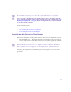
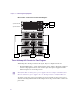
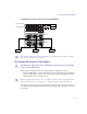
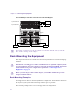
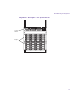
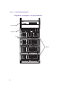
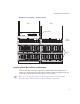
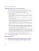
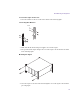
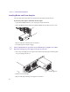
Table Of Contents
- Title Page
- Contents
- Using This Guide
- Avid Unity ISIS System Overview
- Connecting the Equipment
- Configuring Avid Unity ISIS Hardware and Installing Software
- Avid Unity ISIS LED Status
- Loading the Product Recovery DVD
- Enabling the Failover Software
- Adding a System Director to an Existing File System
- Setting IP Addresses for Crossover Link
- Stopping Active System Director
- Configuring Failover Settings
- Creating New Standby File System
- Restarting Existing System Director
- Stopping and Restarting System Directors During Failover
- Creating Failover with Two New Systems
- Setting IP Addresses for Crossover Links
- Configuring Failover Settings
- Creating New File Systems on the A and B System Directors
- Adding a System Director to an Existing File System
- Regulatory and Safety Notices

Chapter 2 Connecting the Equipment
34
Second Example of Power Connection for Two ISIS Engines
n
The 20-amp circuits shown for the System Directors should remain the same for both the
three and two 20-amp circuit examples.
Rack-Mounting the Equipment
This chapter describes how to install and connect the System Director and other workgroup
hardware.
c
Information concerning power, airflow, and dimensions are explained completely in the
Avid Unity ISIS Site Preparation Guide located on the documentation DVD. You should
understand the basic power configurations explained in “Connecting Power to
Equipment” on page 30.
c
Before you start the procedures in this chapter, you should be familiar the previous
chapters in this document.
Rack-Mounting Examples
Avid supports more than one Avid Unity ISIS rack configuration. You should have discussed
the layout for your system with an Avid representative prior to purchase.
The following examples show a few of the supported rack configurations.
Slot 3
Slot 2
Slot 1
Slot 3
Slot 2
Slot 1
Engine
Engine
System Director
20 Amp20 Amp
20 Amp
20 Amp
AA
BAB
B
System Director