
Music Mixer User Manual


D-Command Guide10
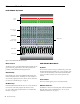
D-Command Fader Module
Fader Module Top Panel
Meter Section
The Meter section on the D-Command Fader Module can dis-
play track levels, plug-in meters, and other parameters de-
pending on D-Command metering preferences.
Channel Strip
Each channel strip on the D-Command Fader Module has
identical channel controls, including two touch-sensitive ro-
tary encoders, display and mode controls, and a touch-sensi-
tive fader. See “Channel Strips” on page 31.
Modifier Keys
Each D-Command Fader Module has a set of four switches in
its lower left corner that duplicate the function of the
Pro Tools computer keyboard modifiers. See “Modifier Key
Switches” on page 37.
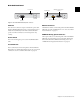
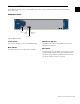
Fader Module Back Panel
AC Power
The AC Power connector accepts a standard AC power cable.
The D-Command Fader Module is auto power-selecting (100V
to 240V) and automatically works with a standard modular
power cord when connected to an AC receptacle in any
country.
Power Switch
The Power switch applies power to the Fader Module.
Ethernet Connector
The Ethernet connector on the back panel of the D-Command
Fader Module provides communication to Pro Tools. See
“Ethernet Connections” on page 17.
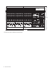
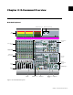
Figure 3. D-Command Fader Module top panel
Channel Strip
Rotary Encoder
section
Meter
section
Channel Strip
Mode controls
Channel faders
Channel Strip
Function controls
Modifier keys