Installation Guide Avigilon™ High Definition H.264 IP Dome Camera Models: 1.0-H3-D1, 1.0-H3-D1-IR, 1.0-H3-D2, 1.3L-H3-D1, 1.3L-H3-D2, 2.0H3-D1, 2.0-H3-D1-IR, 2.0-H3-D2, 3.0W-H3-D1, 3.0W-H3-D1-IR, 3.0W-H3-D2, 5.0-H3-D1, 5.0-H3-D1-IR and 5.
Important Safety Information This manual provides installation and operation information and precautions for the use of this camera. Incorrect installation could cause an unexpected fault. Before installing this equipment read this manual carefully. Please provide this manual to the owner of the equipment for future use.
Regulatory Notices This device complies with part 15 of the FCC Rules. Operation is subject to the following two conditions: (1) This device may not cause harmful interference, and (2) this device must accept any interference received, including interference that may cause undesired operation. This Class B digital apparatus complies with Canadian ICES-003. FCC Notice This equipment has been tested and found to comply with the limits for a Class B digital device, pursuant to Part 15 of the FCC rules.
Legal Notices © 2012 -2015 Avigilon Corporation. All rights reserved. Unless expressly granted in writing, no license is granted with respect to any copyright, industrial design, trademark, patent or other intellectual property rights of Avigilon Corporation or its licensors. AVIGILON is a registered and/or unregistered trademark of Avigilon Corporation in Canada and other jurisdictions worldwide.
Table of Contents Overview 1 Cover View 1 Bottom View 2 Front View 3 Rear View 4 IR View 5 Installation 6 Required Tools and Materials 6 Camera Package Contents 6 Installation Steps 6 Removing the Dome Cover 6 Mounting the Dome Camera 7 Connecting Cables 8 Assigning an IP Address 8 Accessing the Live Video Stream 8 Aiming the Dome Camera 9 (Optional) Configuring Onboard Storage 9 Installing the Dome Cover 9 Focusing the Dome Camera 9 For More Information 10 Cable Conn
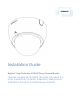
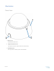
Overview Cover View 1. Dome Cover Vandal proof dome cover. 2. Tamper Resistant Screws Torx captive screws to fix the dome cover to the base. 3. Cable Entry Hole An entry hole for network, power and I/O cables.
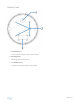
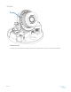
Bottom View 1. Cable Entry Hole An entry hole for network, power and I/O cables. 2. Mounting Holes Mounting points for the camera. 3. Serial Number Tag Product serial number and part number label.
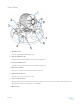
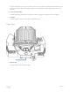
Front View 1. Azimuth Control Provides adjustment of the image angle. 2. Tilt Lock Thumb Screws Provides a locking mechanism for the image tilt adjustment. 3. Pan Lock Thumb Screws Provides a locking mechanism for the image pan adjustment. 4. I/O Connector Block Provides connections to external input/output devices. 5. Audio/Video Connector Accepts a mini-jack connector (3.5 mm). 6. Power Connector Block Accepts a terminal block with either an AC or DC power connection. DC input can be either polarity.
Accepts an Ethernet connection to a network. Server communication and image data transmission occurs over this connection. Also receives power when it is connected to a network that provides Power over Ethernet. 8. Connection Status LED Provides information about device operation. For more information, see LED Indicators on page 14 9. Link LED Indicates if there is an active connection in the Ethernet port. Rear View 1. SD Card Slot Accepts an SD card for onboard storage.
IR View 1. IR Illuminator Ring Provides scene illumination in the IR spectrum. The IR illuminator ring is not included with all models.
Installation Required Tools and Materials l Small slotted screwdriver with 5/64” or 2 mm blade width — for connecting power when not using Power over Ethernet.
the installation is complete. Mounting the Dome Camera Perform the following steps to mount the dome camera to the ceiling or wall: 1. Use the drill template to drill four mounting holes and one cable entry hole in the ceiling or wall. 2. Pull the cables through the cable entry hole in the ceiling or wall, then through the cable entry hole in the dome camera. 3. Drive four screws into the mounting holes to fasten the dome camera to the ceiling or wall.
Connecting Cables Refer to the diagrams in the Overview section for the location of the different connectors. To connect the cables required for proper operation, complete the following: 1. If external input or output devices are part of the installation (for example: door contacts,relays, etc), connect the devices to the I/O Terminals. 2. If an external microphone or external video monitor needs to be connected to the camera, connect the devices to the camera Audio/Video Connector. 3.
Aiming the Dome Camera 1. Loosen the pan and tilt lock screws on the camera. 2. Turn the lens to the desired direction by panning and tilting the lens. 3. Once satisfied, tighten the pan and tilt lock screws to secure the dome camera’s position. 4. Rotate the azimuth control ring to set the image to the correct angle. 5. In the Camera Installation Tool or camera web browser interface, adjust the camera’s Image and Display settings.
For More Information Additional information about setting up and using the device is available in the following guides: l Avigilon™ Control Center Client User Guide l Avigilon™ High Definition H.264 Web Interface User Guide The manuals are available on the Avigilon website: http://avigilon.
Cable Connections Connecting External Power NOTE: Do not perform this procedure if Power over Ethernet (POE) is used. If PoE is not available, the device needs to be powered through the removable power connector block. Refer to the diagrams in this guide for the location of the power connector block. The device can be powered from 12 VDC or 24 VAC. The power consumption information is listed in the product specifications. To connect power to the power connector block, complete the following steps: 1.
1. Ground 2. Input — To activate, connect the Input to the Ground pin. To deactivate, leave disconnected or apply between 3-15 V. 3. Output — When active, Output is internally connected with the Ground pin. Circuit is open when inactive. Maximum load is 25 VDC, 120 mA. 4. * — Relay 5. ** — Switch Connecting to Microphones, Speakers and Video Monitors The camera can be connected to an external microphone, speaker and video monitor through the audio/video connector. The connector is a mini-jack (3.
Figure 2: Mini-jack audio video connector 1. Audio IN 2. Composite Video OUT 3. GND 4.
LED Indicators Once connected to the network, the Connection Status LED will display the progress in connecting to the Network Video Management software. The following table describes what the LEDs indicate: Connection State Connection Status LED Description Obtaining IP Address One short flash every Attempting to obtain an IP address. second Discoverable Two short flashes every second Obtained an IP address but is not connected to the Network Video Management software.
Resetting to Factory Default Settings If the camera no longer functions as expected, you can choose to reset the camera to its factory default settings. Use the firmware revert button to reset the camera. Figure 3: The firmware revert button on the side of the dome camera. 1. Disconnect power from the device. 2. Using a straightened paperclip or similar tool, gently press and hold the firmware revert button. 3. While continuing to hold the button, power the device. Release the button after three seconds.
Setting the IP Address Using the ARP/Ping Method Complete the following steps to configure the camera to use a specific IP address: 1. Locate and copy down the MAC Address (MAC) listed on the Serial Number Tag for reference. 2. Open a Command Prompt window and enter the following commands: a. arp -s For example: arp -s 192.168.1.10 00-18-85-12-45-78 b. ping -l 123 -t For example: ping -l 123 -t 192.168.1.10 3. Reboot the camera. 4.
Cleaning Dome Bubble If the video image becomes blurry or smudged in areas, it may be because the dome bubble requires cleaning. To clean the dome bubble: l Use hand soap or a non-abrasive detergent to wash off dirt or finger prints l Use a microfiber cloth or non-abrasive fabric to dry the dome bubble.
Specifications Camera Audio Input Line input, A/V mini-jack (3.5 mm) Video Output NTSC/PAL, A/V mini-jack (3.5 mm) H3-D1: 3-9mm, F1.2, P-iris Lens H3-D2: 9-22mm, F1.6, P-Iris Onboard Storage SD/SDHC/SDXC slot – minimum class 4; class 6 or better recommended Network Network 100Base-TX Cabling Type CAT5 Connector RJ-45 API ONVIF compliance version 1.02, 2.00, Profile S (www.onvif.org) Security Password protection, HTTPS encryption, digest authentication, WS authentication, user access log, 802.
Environmental Operating Temperature -10 °C to +50 °C (14 °F to 122 °F) Storage Temperature -10 °C to +70 °C (14 °F to 158 °F) Humidity 0-95% non-condensing Certifications Safety UL 60950 CSA 60950 EN 60950-1 WEEE CE ROHS RCM Electromagnetic Emissions FCC Part 15 Subpart B Class B EN 55022 Class B IC ICES-003 Class B Electromagnetic Immunity EN 55024 Class B EN 61000-4-2 EN 61000-4-3 EN 61000-4-4 EN 61000-4-5 EN 61000-4-6 EN 61000-4-11 Specifications 19
Limited Warranty & Technical Support Avigilon warrants to the original consumer purchaser, that this product will be free of defects in material and workmanship for a period of 3 years from date of purchase. The manufacturer’s liability hereunder is limited to replacement of the product, repair of the product or replacement of the product with repaired product at the discretion of the manufacturer.