Installation Guide Avigilon High Definition H.264 IP Dome Camera Models: 1.0-H3-D1, 1.0-H3-D1-IR, 1.0-H3-D2, 1.3L-H3-D1, 2.0-H3-D1, 2.0-H3-D1-IR, 2.0-H3-D2, 3.0W-H3-D1, 3.0W-H3-D1-IR, 3.0W-H3-D2, 5.0-H3-D1, 5.0-H3-D1-IR and 5.
This manual provides installation and operation information and precautions for the use of this dome camera. Incorrect installation could cause an unexpected fault. Before installing this equipment read this manual carefully. Please provide this manual to the owner of the equipment for future use.
English • • (10 W min. for -IR model) or Power over Ethernet (PoE), rated 48 VDC, 6 W min (10 W min. for -IR model). Any external power supply connected to this product may only be connected to another Avigilon product of the same model series. External power connections must be properly insulated. Do not connect directly to mains power for any reason. Caution — Failure to observe the following instructions may result in injury or damage to the dome camera.
This device complies with part 15 of the FCC Rules. Operation is subject to the following two conditions: (1) This device may not cause harmful interference, and (2) this device must accept any interference received, including interference that may cause undesired operation. This Class B digital apparatus complies with Canadian ICES-003.
European Union: English This symbol means that according to local laws and regulations your product should be disposed of separately from household waste. When this product reaches its end of life, take it to a collection point designated by local authorities. Some collection points accept products for free.
English Other Notices Compilation and Publication Notice This manual has been compiled and published covering the latest product descriptions and specifications. The contents of this manual and the specifications of this product are subject to change without notice.
English vi
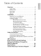
Overview . . . . . . . . . . . . . . . . . . . . . . . . . . . . . . . . . . 1 Cover View . . . . . . . . . . . . . . . . . . . . . . . . . . . . . . . . . . . . 1 Bottom View . . . . . . . . . . . . . . . . . . . . . . . . . . . . . . . . . . . 2 Front View . . . . . . . . . . . . . . . . . . . . . . . . . . . . . . . . . . . . 3 Rear View . . . . . . . . . . . . . . . . . . . . . . . . . . . . . . . . . . . . . 4 IR View . . . . . . . . . . . . . . . . . . . . . . . . . . . . . . . . . . . . . . .
English
English Overview Cover View Tamper Proof Screws Cable Entry Hole Dome Cover Feature Description Dome Cover Vandal proof dome cover constructed out of plastic with a polycarbonate bubble. Tamper Proof Screws TORX tamper-resistant captive screws to fix the dome cover to the base. Cable Entry Hole An entry hole for network, power and I/O cables.
Bottom View English Cable Entry Hole Mounting Holes Serial Number Tag Feature Description Cable Entry Hole An entry hole for network, power and I/O cables. Mounting Holes Mounting points for the dome camera. Serial Number Tag Product serial number and part number label.
English Front View Azimuth Control Tilt Lock Thumb Screw Link LED Connection Status LED Pan Lock Thumb Screw Ethernet Port Power Connector Block I/O Terminals Audio/Video Connector Feature Description Tilt Lock Thumb Screws Provides a locking mechanism for the image tilt adjustment. Pan Lock Thumb Screws Provides a locking mechanism for the image pan adjustment. Azimuth Control Provides adjustment of the image angle. Ethernet Port Accepts an Ethernet connection to a network.
Rear View English SD Card Slot Feature Description SD Card Slot Accepts an SD card for onboard storage. See Mounting the Dome Camera for more information.
English IR View IR Illuminator Ring Feature Description IR Illuminator Ring Provides scene illumination in the IR spectrum. The IR illuminator ring is not included with all models.
English Installation Required Tools and Materials • Small slotted screwdriver with 5/64” or 2 mm blade width — for connecting power when not using Power over Ethernet. Camera Package Contents Ensure the package contains the following: • • • • • Avigilon High Definition IP Dome Camera Terminal block T20 TORX tamper resistant key 4 screws and anchors for solid walls Drill template sticker Installation Steps Complete the following procedures to install the dome camera. 1. 2. 3. 4. 5. 6. 7. 8. 9. 10.
Remove the dome cover by loosening the tamper-proof screws that fix the cover to the base. The tamper resistant key included with the dome camera can be used to loosen the screws. NOTE: Be careful not to scratch or touch the dome bubble. The resulting marks or fingerprints may affect the overall image quality. Try not to touch the dome bubble and keep the protective cover on the bubble until after the installation is complete.
English Figure: Dome camera installation. Connecting Cables Refer to the diagrams in the Overview section for the location of the different connectors. To connect the cables required for proper operation, complete the following: 1. 2. 3. 8 If there are external input or output devices that need to be connected to the camera (for example: door contacts, relays, etc), connect the devices to the camera I/O Terminals. For more information, see Connecting to External Devices.
4. Connect power using one of the following methods: • Power over Ethernet (PoE) Class 3 — If PoE is available, the camera LEDs will turn on. • 5. The Link LED will turn on once a network link has been established. English • External Power — Connect an external 12 VDC or 24 VAC power source to the power connector block. For more information, see Connecting Power. Check that the Connection Status LED indicates the correct state. For more information, see LED Indicators.
English • • Avigilon Camera Installation Tool software application. Camera's web browser interface: http:///. • Network Video Management software application (for example, Avigilon Control Center). NOTE: The default camera username is admin and the default password is admin. Aiming the Dome Camera 1. 2. 3. 4. 5. Loosen the pan and tilt lock screws on the camera. Turn the lens to the desired direction by panning and tilting the lens.
Access the camera’s web interface to enable the onboard storage feature. For more information, see the Avigilon High Definition H.264 Camera Web Interface User Guide. Installing the Dome Cover To install the dome cover, complete the following steps: 1. 2. 3. Rotate the black shield located inside the dome bubble so that it does not block the camera’s field of view. Skip this step if you are installing a dome camera with IR illumination.
English For More Information Additional information about setting up and using the device is available in the following guides: • • • Avigilon Camera Installation Tool User Guide Avigilon Control Center Client User Guide Avigilon High Definition H.264 Web Interface User Guide The manuals are available on the Avigilon website: http://avigilon.com/ support-and-downloads.
English Cable Connections Connecting External Power NOTE: Do not perform this procedure if Power over Ethernet (POE) is used. If PoE is not available, the dome camera needs to be powered through the removable power connector block. Refer to the diagrams in this guide for the location of the power connector block. The device can be powered from 12 VDC or 24 VAC. The power consumption information is listed in the product specifications.
Connecting to External Devices English External devices are connected to the camera through the I/O terminal. The pinout for the I/O terminal is shown in the following table and diagram. Table: External I/O Terminals Pin Function Description 1 Ground Ground 2 Input To activate, connect the Input to the Ground pin. To deactivate, leave disconnected or apply between 3-15 V. 3 Output When active, Output is internally connected with the Ground pin. Circuit is open when inactive.
English Connecting to Microphones, Speakers and Video Monitors The camera can be connected to an external microphone, speaker and video monitor through the audio/video connector. The connector is a mini-jack (3.5 mm), and the pinout for it is shown in the following diagram. NOTE: The camera only supports line level mono audio input and an NTSC or PAL video output. The video output signal is determined by the camera flicker control setting.
English LED Indicators Once the camera is connected to the network, the Connection Status LED will display the camera’s progress in connecting to the Network Video Management software. The following table describes what the LEDs indicate: Table: LED Indicators Connection State Connection Status LED Description Obtaining IP One short Address flash every second Attempting to obtain an IP address.
English Reset to Factory Default Settings If the camera no longer functions as expected, you can choose to restore the camera to its factory default settings. Use the firmware revert button to reset the camera. Firmware Revert Button Figure: The firmware revert button on the side of the dome camera. 1. Disconnect power from the camera. 2. Using a straightened paperclip or similar tool, gently press and hold the firmware revert button. While continuing to hold the button, power the device.
English Setting the IP Address Through the ARP/Ping Method Complete the following steps to configure the camera to use a specific IP address: 1. 2. Locate and copy down the MAC Address (MAC) listed on the Serial Number Tag for reference. Open a Command Prompt window and enter the following commands: a. arp -s For example: arp -s 192.168.1.10 00-1885-12-45-78 b. 3. 4. 18 ping -l 123 -t For example: ping -l 123 -t 192.168.1.
H3-D1 Camera Audio Input Video Output Lens Onboard Storage Network Network Cabling Type Connector API Security Protocols Streaming Protocols Mechanical Dimensions ØxH Weight Dome Bubble Body Housing Finish Adjustment Range Electrical Power Consumption H3-D2 Line input, A/V mini-jack (3.5 mm) NTSC/PAL, A/V mini-jack (3.5 mm) 3-9mm, F1.2, P-iris 9-22mm, F1.6, P-Iris SD/SDHC/SDXC slot – minimum class 4; class 6 or better recommended 100Base-TX CAT5 RJ-45 ONVIF compliance version 1.02, 2.00, Profile S (www.
English Limited Warranty & Technical Support Avigilon warrants to the original consumer purchaser, that this product will be free of defects in material and workmanship for a period of 3 years from date of purchase. The manufacturer’s liability hereunder is limited to replacement of the product, repair of the product or replacement of the product with repaired product at the discretion of the manufacturer.