Installation Guide Avigilon Panoramic High Definition IP Dome Camera Model: 8.
English English Important Safety Information This manual provides installation and operation information and precautions for the use of this dome camera. Incorrect installation could cause an unexpected fault. Before installing this equipment read this manual carefully. Please provide this manual to the owner of the equipment for future use.
English • • Any external power supply connected to this product may only be connected to another Avigilon product of the same model series. External power connections must be properly insulated. Do not connect directly to mains power for any reason. Caution — Failure to observe the following instructions may result in injury or damage to the dome camera. • • • • • • • • • • • ii Do not install near any heat sources such as radiators, heat registers, stoves, or other sources of heat.
English English Regulator Notices This device complies with part 15 of the FCC Rules. Operation is subject to the following two conditions: (1) This device may not cause harmful interference, and (2) this device must accept any interference received, including interference that may cause undesired operation. This product complies with IEC 60825-1 (A2:2001) - CLASS 1 LED PRODUCT. Maximum radiated output power: 740 mW. This Class A digital apparatus complies with Canadian ICES-003.
English European Union: This symbol means that according to local laws and regulations your product should be disposed of separately from household waste. When this product reaches its end of life, take it to a collection point designated by local authorities. Some collection points accept products for free.
English English Other Notices Compilation and Publication Notice This manual has been compiled and published covering the latest product descriptions and specifications. The contents of this manual and the specifications of this product are subject to change without notice.
English Table of Contents Overview . . . . . . . . . . . . . . . . . . . . . . . . . . . . . . 1 Cover View . . . . . . . . . . . . . . . . . . . . . . . . . . . . . . . Bottom View . . . . . . . . . . . . . . . . . . . . . . . . . . . . . . Front View . . . . . . . . . . . . . . . . . . . . . . . . . . . . . . . . Rear View . . . . . . . . . . . . . . . . . . . . . . . . . . . . . . . . Heater View . . . . . . . . . . . . . . . . . . . . . . . . . . . . . . 1 2 3 4 5 Installation . . . . . . . . . . . .
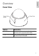
English English Overview Cover View Tamper Proof Screws Dome Cover Feature Description Dome Cover Vandal proof dome cover constructed out of aluminum with a polycarbonate bubble. Tamper Proof Screws TORX tamper-resistant captive screws to fix the dome cover to the base.
English Bottom View Dome Mounting Slot Cable Entry Hole Dome Mounting Slot Dome Mounting Slot Serial Number Tag Feature Description Cable Entry Hole An entry hole for network, power and I/O cables. Dome Mounting Slot Mounting points for the dome camera. Serial Number Tag Product serial number and part number label.
English English Front View Ethernet Port Power Connector Block Audio Connector Feature Ethernet Port I/O Terminals Description Accepts an Ethernet connection to a network. Server communication and image data transmission occurs over this connection. Also receives power when it is connected to a network that provides Power over Ethernet. The Ethernet Port has two status lights indicating link (left) and activity (right).
English Rear View Connection Status LED Image 180° Rotation Switch Feature Description Connection Status LED Provides information about the network connection. See the section about connecting to the network video recorder for more information. The Connection Status LED can be turned off for operating in covert installations. See the Avigilon Control Center Client User Guide for more information. Image Rotation Rotates the image by a 180˚ angle.
English English Heater View Heater Feature Description Heater Provides heat for the camera to extend the operating temperature range. The heater is not included with all models.
English Installation Required Tools and Materials • Small slotted screwdriver with 5/64” or 2 mm blade width — for connecting power when not using Power over Ethernet. Package Contents Ensure the package contains the following: • • • • • Avigilon Panoramic High Definition IP Dome Camera Terminal block T20 TORX tamper resistant key 3 screws and anchors for solid walls Drill template Installation Steps Complete the following procedures to install the dome camera. 1. 2. 3. 4. 5.
The dome camera can be mounted to a surface on its own or using one of the four dome camera mounting accessories: indoor electrical box mounting plate, indoor in-ceiling mount, indoor/outdoor mounting base, and indoor/outdoor pendant mount. To mount the dome camera, complete the following steps: 1. 2. 3. 4. 5. Using the drill template, drill three mounting holes and one cable entry hole in the ceiling/ wall. If using a dome camera mounting accessory, this step is not necessary.
English Connecting Power NOTE: Do not perform this procedure if Power over Ethernet (POE) is used. If PoE is not available, the dome camera needs to be powered through the removable power connector block. Refer to the diagrams in this guide for the location of the power connector block. The device can be powered from 12 VDC or 24 VAC. The power consumption information is listed in the product specifications. To connect power to the power connector block, complete the following steps: 1. 2.
English English Table:Wire Length for Different Wire Gauges Maximum Run Length (ft [m]) Wire Gauge AWG mm2 24 VAC 12 VDC 24 0.2 164[50] 43[13] 22 0.33 267[81] 71[21] 20 0.5 428[130] 114[34] 18 0.82 680[207] 181[55] 16 1.3 1071[326] 285[87] Aiming the Dome Camera 1. 2. 3. 4. Loosen the mounting screws. Turn the lenses to the desired direction by rotating the base. Once satisfied, secure the dome camera’s position by tightening the mounting screws.
English The connection status LEDs show the progress in connecting to the server and are described in the following table.
English English Advanced Features Upgrading the Firmware The firmware can be field-upgraded through the Avigilon Control Center software. Consult the software user guide for details on how firmware upgrades are performed. It is possible for the firmware to become corrupted during an upgrade — for example, if power is lost during the upgrade process. If this occurs, the dome camera can be reverted to run from bootstrap firmware. Once reverted, it can be upgraded as usual.
English Connecting to External Devices External devices are connected through the I/O terminal. The pinout for the I/O terminal is shown in the following table and diagram. Consult the software user guide for details on how to configure the external devices. Table:External I/O Terminals Pin Function Description 1 GND Ground for RS-485 interface. 2 RS-485 RX/TX+ 3 RS-485 RX/TX- Half-duplex RS-485 interface for controlling external equipment 4 Input (-)/Output A Shared pin for Input and Output.
The dome camera can be connected to an external microphone and speaker through the audio connector. The audio connector is a 3.5 mm (1/8”) input for a mono microphone or a line-in mono signal. The left channel of the stereo signal is used. The connector pinout is shown in the following diagram. Consult the software user guide for details on how configure the audio input and output. Audio IN Audio OUT GND Figure: Audio connector.
English Cleaning Body Use a dry or lightly dampened cloth to clean the camera body. Caution — Do not use strong or abrasive detergents when cleaning the camera body.
English English Specifications Network Network Cabling Type Connector Security Protocol 100Base-TX CAT5 RJ-45 SSL UDP, TCP, SOAP, DHCP, Zeroconf Mechanical Dimensions ØxH Weight Dome Bubble Body Housing Finish Adjustment Range 150mm x 120mm 5.9” x 4.7” 0.91kg (2.0lbs) without lens Polycarbonate, clear Aluminum Surface mount, vandal resistant Powder coat, cool gray 2 360° pan, 180° tilt, 180° azimuth Electrical Power Source Power Consumption Power Connector VDC: 12-24 V VAC: 24 V PoE: IEEE802.
English Limited Warranty & Technical Support Avigilon warrants to the original consumer purchaser, that this product will be free of defects in material and workmanship for a period of 3 years from date of purchase. The manufacturer’s liability hereunder is limited to replacement of the product, repair of the product or replacement of the product with repaired product at the discretion of the manufacturer.
© 11/7/11 Avigilon Corporation