Access Control Manager Application Configuration and Work Flow Guide
Access Control Manager Version 5.0/AV01-1213 Version 5.0 Copyright© 2012-2013 Avigilon Inc. Avigilon Inc. Box 378 #101-1001 West Broadway Vancouver, British Columbia V6H 4E4 Canada Phone:888.281.5182 Web:www.avigilon.
Access Control Manager Getting Help If you encounter a problem that is not discussed in available Avigilon Access Control Manager user guides or online help files, and need technical support, please contact your local Value Added Reseller (VAR) or Avigilon support (888.281.5182). When contacting your VAR, please be sure to have your registration material, serial number, and software version number available. For future reference, record these numbers here.
Table of Contents Overview . . . . . . . . . . . . . . . . . . . . . . . . . . . . . . . . . . . . . . . . . . . . . . . 1 Flowchart . . . . . . . . . . . . . . . . . . . . . . . . . . . . . . . . . . . . . . . . . . . . . . . . . . . . . . 2 Access Control Manager Workflow . . . . . . . . . . . . . . . . . . . . . . . . . 3 Connecting and Accessing the Access Control Manager Appliance . . . . . . . . . . . . . . . . . . . . . . . . . . . . . . . . . . . . . . . . . . . . . . . . . . . . .
Overview Thank you for your purchase of the Access Control Manager software. This configuration and workflow guide will walk you through the steps required to connect and configure your new Access Control Manager system. This is not a comprehensive guide of every feature and field in the system. For that, you can review the Access Control Manager online help files.
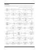
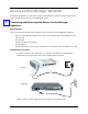
Flowchart The flowchart below shows the basic steps you should follow to complete the setup process.
Access Control Manager Workflow The following workflow is divided into sections and subsections representing the steps you will take in configuring the Access Control Manager system.
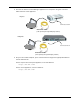
2. Connect the Access Control Manager appliance to a computer using the crossover cable to Port 2 of the appliance. Express Connect to Port 2 Crossover Cable (sold separately through third-party retailers) Enterprise Connect to Port 2 Crossover Cable (sold separately through third-party retailers) 3. On your connected computer, open a web browser and type the appropriate address into the address bar. For the express and enterprise appliance, enter this address: https://169.254.1.
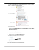
At this point, you will probably see a message indicating that you are trying to reach an unknown or insecure site, like these examples: If this is Firefox: If this is Internet Explorer: If this is Safari: If this is Chrome: 4. Do one of these things: • If this is Firefox, click the “Or you can add an exception...” or “I understand the risks” link, click the Add Exception button, click Get Certificate, then click Confirm Security Exception button.
Login: admin Password: admin NOTE: We highly recommend that you change the login and password for the system administrator account as part of the configuring of your new appliance. 6. Press Sign in. The home page appears like this example: 7. From the Setup section in the upper right corner, click Settings then System Settings. 8. Make changes as required to the language displayed as well as the token expiration time and the password strength, as required. 9. From the Setup section, click Appliance.
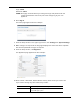
Host Name This is the DNS name for this appliance and is identified as such under the 'DNS Name' field on the Appliance Listing page. Domain Name Enter the domain name where this appliance resides. Name Server Enter the name of the domain server. Time Server Enter the time server connected to this appliance. Time zone From the drop-down pick list, specify the time zone where this appliance resides.
Specify the port number used to set the port you wish this appliance to use in order to listen for IP client panel connections. Mercury Client Port Note: This must be the same port configured on all of the IP Client panels that will connect to this appliance. Mercury-Require TLS Check this box, if required, to encrypt connections between the appliance and the Mercury Panel.
12. Click the button. First click the Save button then click the Reboot Appliance button. 13. Once the appliance reboots, click the About tab. The About page appears like the following example. EULA must be completed before you can install the hardware The essential information about this appliance, including the appliance license string and key are displayed. 14. For initial setup, click the “View End User License Agreement Terms and Conditions” link.
The Software Terms and Conditions form appears like this example: 15. Review the terms then enter the name of this company, the name of the administrator or owner, and the title of the person whose name appears here, then click Back. 16. Reboot the appliance as explained in Step 10, then click Logout at the top of the page to log out of the appliance. 17. Log in and click on Appliance. The Appliance property sheet appears. 18. Click on the Ports tab. The Ports page appears like this example: 19.
If you need to change any other values, they include: Name This field contains the name of the Ethernet port. Initially, the name that appears is the current or default name of the port; however, you can enter a new name if you require. Link Status This read-only field indicates whether the connection is currently up or down. IP Address Enter the IP address for this port. If you aren't sure what the address is, consult your IT administrator.
a. Remove the crossover cable and move the appliance to its required position in the system. b. Using a standard Ethernet cable, connect one end of the RJ-45 to an available RJ45 port on the appliance. c. Connect the other end of the Ethernet cable to the network. Express Enterprise If this is a Virtual appliance, ignored this step. NOTE: Access Control Manager only supports connectivity to Mercury controllers through IP. Serial connectivity to these panels is not currently supported.
2 Panels After setting up the appliance, your next step is to configure the panels to which this appliance is connected. For this document, we are only interested in Mercury Security panels. To configure Mercury Security panels: 1. From the icon task bar of the home page, click on Physical Access then click on Panels. 2. Click the button to add a panel. The Panel Add page appears like this example: 3. Assign the new panel a name, choose an appliance, and select Mercury for vendor type.
Lenel Mercury LNL-1300 MR50 LNL-1320 MR52 — MR51e 6. Leave the rest of the fields at their default settings and click settings. to save your The Sub-panels page appears like this example: 7. Choose the appropriate quantity of downstream panels attached to this master panel. 8. Click to save your settings. The Panel Configure page appears like this example: 9. Make changes, if required, and click to save your settings.
Partitions From the window, select one or more partitions to which this panel will be assigned. Only those partitions presently defined by this system appear in this list. Model This read-only field displays the Panel model to which the sub panel is connected. Time zone Identifies which time zone applicable to the panel. Select the time zone from the drop-down list. Only those time zones previously defined for this system can appear in this list.
From the window, select one or more partitions to which this panel will be assigned. Partitions Only those partitions presently defined by this system appear in this list. 12. Click IP Address Enter the IP address of this panel. Reply Timeout From the list, select the number of milliseconds this panel is allowed to wait for a reply from the primary Access Control Manager host.
The Firmware listing like this example: 15. Locate the firmware for the panel you installed and configured, then click the green check mark to download the firmware to the panel. NOTE: For instructions on copying firmware to your host computer, refer to the Access Control Manager online help. The system asks you to confirm that you want to download the firmware to the panel. 16. Click Yes. The firmware is installed. This takes approximately five minutes. 17.
6. Proceed to add Areas (page 19). If you do not require areas in order to define the doors, you can skip Areas and go directly to Doors (page 21).
3 Areas Areas are zones the Access Control Manager assigns to define a physical area within a secured location. This area can be relatively small, like a lab or a store room, or large, like a collection of buildings. Areas often incorporate one or more doors with their attached inputs and outputs. Once an area is defined, it can be assigned to a role or policy indicating that portion of a facility or company to which assigned users are limited.
These fields include: From the drop-down pick list, select one of the existing appliances in which this area appears. Appliance Only those appliances currently defined for this system appear in this list. Name Enter the name of this area Maximum Occupancy Enter the maximum number of cardholders allowed in this area at a specified time. Log Min Reached Record a transaction when the minimum count for this area is reached.
4 Doors After you have configured both the appliance and the panels it controls, it is time to create and configure each door associated with the created panels. To create and configure doors: 1. From the icon task bar on the home page, click Physical Access. 2. Click Doors. The Doors Listing page appears like this example: 3. Click the button. The Door Add screen appears like this example: 4. Enter the following information: • Door Name • An Alternate name (optional) • Location (optional) 5.
The Door Add page expands to include basic door configuration values, like the following example: The fields on this page include: Name Enter the name of this panel. Partitions From the window, select the partitions to which this door should be added. Only those partitions currently defined by the system appear in this window. Alt Name Enter a description of this panel, such as 'front door' or 'lab door'. Address This is a display-only field that is generated by the Access Control Manager.
Offline Mode Specifies the entry mode used for the door if the door controller is no longer communicating with the panel. Note: In many cases, the limited memory of most readers in offline mode requires a very simple solution to entry or exit, such as use of a facility code. Select the Offline Mode option from the drop-down list. Custom mode From the drop-down list, select the special mode to use during a time zone specified in the 'Custom Schedule' field.
Door Forced Filter Check this box to enable the filter feature for door forced alarms. There are instances when a door is either slow to close or is slammed shut and bounces open for a few seconds. With this filter, the monitor allows three seconds for a door to close before issuing an alarm. Log All Access as Used Check this box to log all access grant transactions as if the person used the door.
Alt Name Identifies an alternate name for the door. If there is an additional name the door is identified by, enter this alternate name. Location Identifies the location of the door. Enter a description of the door’s location. Appliance Identifies the appliance of the door. This is a display only field when in edit mode. Vendor Identifies the vendor of the door. This is a display only field when in edit mode.
Strike Mode Defines when a door should unlock. Specifies if the strike is deactivated when the door is opened, when the door is closed, or when the strike timer expires. Select the strike mode from the drop-down list. Cut short when open – the strike is deactivated on open Turn off on close – the strike is deactivated on close. LED Mode Specifies how the reader LEDs are to be displayed. Select the LED mode from the drop-down list. Your choice is 1, 2, or 3.
The Hardware page appears like this example: The fields on this page include: If a sub-panel has been assigned as the option for any of the following fields then saved, the edit sub-panel icon, this example: , will appear as shown in Click the icon to edit the sub-panel associated with the currently displayed option. There are three screens that can appear: • If you click at the 'Reader' or 'Alt Reader' pick list, a subpanel reader edit page can appear.
Alt Reader Select the option you require from the drop-down list. This identifies the subpanel and reader number of a secondary reader. A secondary reader is typically used for the secure side door or a biometric. If you select a sub-panel, the appears to the right of this selection. Click to bring up the edit page for this option. REX #1 Select the option you require from the drop-down list. This identifies the subpanel and input number connected to the first request-to-exit switch.
The Interlocks page appears like this example: Interlocks allow you to configure inputs and outputs connected to this door. NOTE: For more on interlocks, refer to the Access Control Manager online help. 14. Click the Cameras tab. The Cameras page appears like this example: The fields on this page include: Camera Type From the drop-down list, select the type of camera you want to add.
• The Access page is a quick reference by door to show what access groups, roles and identities have access to that door. • The Events page provides a record of both local and global events this door has detected. • The Transactions page displays a list of all transactions that have included use of this door. For more on all these functions, refer to the online help. 16. When you’ve finished entering all relevant values on the required pages, click to save these settings.
5 EOL Resistance End-of-line resistance refers to resistance levels that must be maintained for input points. Input devices used with doors from vendors, such as Mercury Security, measure resistance, in ohms, on the circuit. This corresponds to a steady state. If the resistance drops across the circuit, an alarm is sent back to the Access Control Manager. To define a resistance level: 1. From the icon task bar on the home page, click Physical Access. 2. From the sub-options list, click EOL Resistance. 3.
to: Select from the drop-down list the ending value of the inactive range. Values range from 100 to 9950 ohms in 50-ohm increments. Active Range Select from the drop-down list the beginning value of the active range. Values range from 100 to 9950 ohms in 50-ohm increments. to: Select from the drop-down list the ending value of the active range. Values range from 100 to 9950 ohms in 50-ohm increments.
6 Schedules A schedule is a time period defined for use by the system. It is an editable, reusable time template that can be used to control such things as when a door is accessible or when a device is activated. A user’s access privileges are the result of a three-way relationship that is created between a • • • group of users secured device schedule To create a new schedule: 1. From the Setup Links section of the home page, select Settings.
Mode Select the mode from the drop-down list. The options include: ON – turns the current schedule on OFF – turns the current schedule off SCAN – runs the schedule using its current set of parameters Partitions Select one or more existing partitions to which you want this schedule assigned. Only those partitions currently defined for this system appear in this window. Su - Sa Specify the days of the week that the schedule is active. Check the boxes for each day the schedule is active.
7 Holidays Holidays are those days during the year when normal security policy may not be followed, either because it is a vacation or because a different entry and exit pattern is observed. Such days as Christmas and New Year's Day are examples of holidays. To add a new holiday: 1. From the Setups section of the home page, click or mouse-over the Settings option. 2. From the drop-down option list, click the Holidays sub-option.
Partitions From the window, select one or more partitions to which you want to assign this holiday. Only those partitions previously defined for this system appear in this window. If no partitions are defined for this system, this field does not appear. Type Identifies the type of holiday. The holiday type is a number from 1 to 8. This number is user-defined. For example, security might define 1 as government, 2 as cultural, and 3 as company. Enter a value from 1 – 8. 5.
Policies Policies are limits that can be imposed on people and security devices within the Access Control Manager system. A policy is an aggregation of pre-selected hardware and software components that can be applied to groups, and through those groups, assign them to persons. For example, you can define a 'Technician' policy which restricts anyone who is a member of that policy to specific doors and areas associated with the company's laboratories.
Output Check this box to indicate that this policy affects outputs. An output page is added to this property sheet. 4. Click the button. The confirmation message, “Policy was successfully created.” displayed. The Policy properties edit screen appears like this example: Only those components you select on the policy page (plus the Mercury page) are represented on this screen. 5. Click each page in turn and make changes to that page as required.
8 Groups Groups combine one or more existing policies with the members (identities) who can use them. In order to create a group, you must first create one or more policies and one or more identities with which these policies are associated. Policies can also be assigned to people through the Identities assignment feature. In addition, the groups feature enables the operator to perform batch updates on groups associated with a particular identity profile.
5. Click the button. The confirmation message, “Group was successfully created.” displayed. The Group properties edit screen appears like this example: 6. Click the Policies tab. The Policies page appears like this example: 7. Assign policies to the newly created group as needed. 8. Click the button to save your changes. 9. Click the Members tab and the Member page appears like this example: 10. Assign members as required to the newly created group. 11. Click the button to save your changes. 12.
9 Card Formats Readers that control access to and exit from doors come in many varieties and use many different card protocols. The most commonly used card formats have been Wiegand and magnetic stripe; however, newer cards, using embedded chips, like Smart Cards, and proprietary formats have become more popular with the increase of security requirements.
Offset The offset number for this code. Max Digits The maximum number of digits this card format can possess. Min Digits The minimum number of digits this card format can possess. ABA Mag only. Even Parity Length The even parity length of the number on this card format. Wiegand only. Event Parity Location The location in the number string where the even parity bits reside. Wiegand only. Odd Parity Length The length of the odd parity bits on this card format. Wiegand only.
Once you have defined a card format, the format appears on the Door Operators page as a card format option, as shown in this example: 43
10 Event Types Event types are classifications of events that may occur during the operation of the Access Control Manager system. Event types are associated with specific event sources, such as doors, panels, and systems. NOTE: Particularly for initial installation, you can accept the default event types. To add or change event types: 1. From the Setup Links section of the home page, click or mouse-over the Settings option. 2. From the available sub-options, select Event Types.
These fields include: Name Identifies the event type. Enter a brief, meaningful name for the event type, such as “Door Held Open”. Suppress Schedule Pick from the drop-down list a schedule that is suppressed when this event type is triggered. Only those schedules currently defined for this system appear in this list. Priority Specifies the alarm priority number. The Alarm Monitor stacks alarms on the screen according to their priority.
11 Events Events include all messages and alarms issued by specific devices within the Access Control Manager system. Events are categorized by Event Types within Access Control Manager. Both events and event types can be modified or added as required for a specific installation. NOTE: Particularly for initial installation, you can accept the default events. All available events are provided by default. You cannot create additional events; however, you can edit existing events.
The Edit Event screen appears like this example: 4. Make changes to these fields as required. These fields include: Name Enter a name for this event. Return Enter a name for the return-to-normal (RTN) event. Event Type Select from the drop-down list the event type for this event. Only those event types current defined for this system appear in this list. Source Type Select from the drop-down list the device where this event originates. Priority Specify the priority of this event.
Masked Check this box to indicate that this a masked event. Logged Check this box to log the event. Show Video Check this box to auto-launch video camera feed on alarm. This feature only works if video is enabled. Two Persons Required To Clear Check this box to specify that two people are required to acknowledge and clear this event. If this box is checked then the operator that executes the clear cannot be the same operator that executed the Acknowledge.
12 Roles Roles limit or regulate the number of tasks that a specific user can perform within the Access Control Manager system. That is, use the Roles feature to associate a user with one or more application tasks. If a user tries to perform a task, such as generating reports, for which their role does not qualify them, the feature is not available to them. To access this feature: 1. From the icon task bar on the home page, click the Roles option.
Partitions Click to highlight those partitions you want to make members of this role. Only those partitions previously defined for this system appear in this window. If no partitions are defined for this system, this field does not appear. Installed 4. Click on the Check this box to indicate that this role is active and ready for use. button. Upon successfully adding a role, the Role Edit property screen appears like the following example: 5.
13 Access Groups Before creating a role, we recommend that you define your required access groups. Access Groups combine a schedule (time) with doors within the system. Access Groups define the doors and times that can be accessed by a specified role. To add one or more access groups: 1. From the icon task bar on the home page, click Roles. The Roles Listing page appears. 2. From the sub-options bar, click Access Groups.
This includes adding doors from the ‘Available’ window to the ‘Members’ window by selecting the selected door, then click the icon. 9. Click the Access tab. The Access page appears as shown in this example: 10. Review information as required. 11. If required, click the Audit tab. The Audit page appears like this example: 12. Review the audit history on this page as needed. 13. When you're finished, click . You are returned to the Access Groups Listing page with the newly-defined Access Group listed.
14 Delegation Groups Delegation (permissions) authorizes certain persons or groups of persons within the Access Control Manager database to perform predefined functions. In essence, this means that delegation groups are associations of identities with assigned Access Control Manager features. Before creating a role it is recommended that you determine the required delegations or permissions for that role. To add one or more delegation groups: 1.
The Delegation Groups Edit page appears like this example: Move available features to the ‘Members’ window as required 7. Define this group by adding features in this manner: a. In the ‘Available’ window, click to select a single function, click + Ctrl selects multiple non-sequential functions, or click + Shift to select sequential functions.
15 Partitions Access Control Manager utilizes partitions to limit the access of operators, devices, and users to only specified roles. This enables Access Control Manager to provide different levels of access to almost any element of the system. For example, say that only security guards are allowed to enter the Security Monitor room.
6. When, you're finished, click again. You are returned to the Partitions Listing page with the newly-defined partition on the list. For more on this, refer to Roles on page 49.
16 Badge Designer The Badge Designer is the utility the Access Control Manager uses to design badge templates for inclusion in badge holder credentials. The Designer consists of several features including: • • • • • User-defined field definitions Background color selection for both badge and components Photo frame placement Text placement Logo and insignia placement To create a badge template: 1. From the Setups section on the home page, click the Settings option.
The designated badge template add page appears like this example: 4. Enter a name for this badge template in the ‘Name’ field. 5. Specify the size of the badge you require in the ‘Size’ field. 6. If required, select one or more partitions this badge template is a member of. Only those partitions previously defined for this system appear in this window. 7. Design the badge like this: • To create a background, click the ‘BG Color’ field and specify a background for this badge template.
10. When you're finished customizing this template, click once again. A message appears indicating the success of the badge template creation. 11. Click and you are returned to the Badge Template Listing page with the newly defined badge template in the list. Changing a Background When you open a new badge template or edit an existing one, the canvas background like this example appears: To change the background: 1. Click on the ‘BG Color’ box. The color palette appears. 2.
The number in the Color field changes to reflect your choice. 4. If required, slide up or down the vertical slide bar to change the color still further. 5. When you're finished with this palette, click OK. 6. Click the icon to impose the new color on the canvas or other element. Adding Pictures When you click following example: Photo , an element entitled PHOTO is added to the Attributes list, like the Toggle this word to hide or reveal the fields.
NOTE: None of the values entered here are reflected on the canvas until you have saved the screen by clicking . Once saved, the preview pane displays the relevant image. Adding Database Fields Database fields are essentially placeholders for information that is supplied by the Identities database. These fields are populated by data supplied for the specific badge holder.
BG Color Enter the color you require for the background of this DB field. When you click on this field, a color palette appears. Select the general color, then fine tune it as required. Each change you make to the color is reflected on the work space. Font Select from the drop-down list the font you want used for the text in this data field. Font size Select from the drop-down list the font size you want used for the text in this data field.
When you click the button, a Text field appears, like this example: Text field and associated properties You can drag this placeholder to another location... Notice that a text placeholder appears on the canvas. Use your mouse to drag this text placeholder to the required position on the canvas, or alternatively fine-tune the position using the Location field. The fields in this section are described below: Text Enter the text you want to appear on this template.
Text Color Enter the color you require for the text used in this field. When you click on this field, a color palette appears. Select the general color, then fine tune it as required. Each change you make to the text color is reflected on the canvas only after you have saved it. Opacity In the text box, enter the percentage of opacity you want for the selected text color. The lower the number, the fainter the color that appears.
Maintain Aspect Click to check this box designating that resizing this graphic will not change the aspect ratio of the image. Using this feature you can avoid distorting the image. NOTE: None of the values entered here are reflected on the canvas until you have saved the screen by clicking . The Preview pane appears with the new data field reflected. Badge Camera Configuration The Access Control Manager enables the qualified operator to capture photos from a networked camera.
The IP Camera Listing page appears like this example. 3. Select one of the currently available device types: • • • • For an IP-based camera, go to step 4. For an Exacq server, click the Exacq tab and the Exacq Servers listing page appears. For a Pelco server, click the Pelco tab and the Pelco Server listing page appears. For a LifeSafety power supply, click the LifeSafety tab and the LifeSafety power listing page appears.
Preview URL Enter the URL or web address, if required, of this camera's web-based application showing a preview of the finished picture. Device Login Enter the login name that will enable access to this device. Many cameras accessed over the network require security to use. The Access Control Manager's device login is supplied by default. Device Password Enter the password that will enable access to this device. Many cameras accessed over the network require security to use.
File to Upload Either enter the name of the file required to run this server or click the button and find the required file. Username If required, enter the user name used to access this server. This user name is automatically entered whenever the server is accessed. Password If required, enter the password used to access this server. This password is automatically entered whenever the server is accessed.
VidProxyUrl The URL used as a translator between the appliance and the server. VidProxyImageUrl The URL used to store the video captured by the Avigilon server. Installed Check this box to indicate that this server is connected and working properly. Cameras The name and UUID of each camera this server accesses, their current status, whether they are PTZ or not, and their zoom capability. Salient Server Name The names of the video server for this system.
Username The name the user enters in order to gain access to this server. Password The password the user enters in order to gain access to this server. VidProxyUrl The URL used as a translator between the appliance and the server. VidProxyImageUrl The URL used to store the video captured by the Milestone server. Installed Check this box to indicate that this server is connected and working properly. 6.
17 User-Defined Fields and Lists User-defined fields are custom fields added to the Identity or other custom forms that the user can use to capture information the organization requires in order to define Identities. User lists are data or user fields located within identities that are associated with a drop-down box within the Identities configuration screens. User lists allow the system administrator to predefine the contents of these drop-down boxes. User-Defined Fields To add a user-defined field: 1.
You can also use this feature to create additional tabbed pages for an identity form. For more on this, refer to the Access Control Manager online help. User Lists You cannot add new lists; however, you can add options to existing lists. To add one or more items to an existing field: 1. From the Setup Links on the home page, click or mouse-over Settings. The Settings main page appears. 2. From the drop-down option list, click User Lists.
18 Routing The routing group is a method for associating specific event types with designated access groups that are effective during a specified time interval. In other words, a routing group consists of the following components: • • • • A schedule indicating how routing should take place based on the transaction timestamp A schedule qualifier that indicates how the schedule should be interpreted. A list of event types.
Schedule From the drop-down list, select the interval during which this routing group is active. The current options are: • Never Active - This schedule is never active. Nothing is routed. • 24 Hours Active - This schedule is always active. Everything is routed Schedule Qualifier From the drop-down list, select the option that qualifies the schedule.
The Groups page appears like this example: Move available access groups to the members window as required 10. Associate available access groups with this routing group as required. 11. When you're finished, click . You are returned to the Routing Groups Listing page.
19 Collaboration Collaboration provides the ability to exchange data between the Access Control Manager appliance application and a large number of other database types. NOTE: This is normally a second-level feature and need not be performed initially. For more on this, refer to the Access Control Manager online help and the Collaboration Administration Summary.
20 Identities The Identities feature is used to enroll employees and all other workers and service personnel who require access to a facility or location maintained and overseen by the Access Control Manager system. Adding Identities To add a new Identity: 1. From the home page icon task bar, click Identities. The Identities Listing page appears like this example: 2. Click the button.
The Identity Add page appears like this example: The fields on this page include: Identity Information Photo If you have either imported an image or captured an image for this identity, the photograph appears to the left of the Identity Information fields. Last Name Enter the last name of the user. This field is required. First Name Enter the first name of the user. This field is required. Middle Name Enter the middle initial.
Status Select the option from the pick list that describes the current status of this new user. Active - this is a current user. Expired - this user's access has expired. Lost - this user's access card/badge is reported lost. Stolen - this user's access card/badge is reported stolen. This field is required. Type From the drop-down list, select the type of identity this is. Default values include Employee, Contractor, and Visitor.
Remote Domain From the drop-down list, select an external domain (a domain outside this security system) from which this identity can seek authentication. Only those external domain previously defined by the system appear in this list. Record Modification This read-only field indicates the last time and date this user's identity was modified.
The Tokens page appears like this example: The fields on this page include: Embossed Number Enter the number embossed on the card that will be issued to this user. This is only required if a physical card is being issued. Internal Number Enter the actual number encoded on the ID card. PIN Enter the number this card requires to be entered at a reader in order to grant access to this user or perform the function for which the token was created.
Deactivate Date Click inside this field and use the calendar to specify the date when this token is deactivated. Alternatively, enter the date using the keyboard. Last Door Indicates the last door at which this token was used to gain access. Last Time Indicates the last time this token was used to gain access. Click this button to save the current settings. Click this button to exit this page and return to the higher level screen. 8. Customize tokens for this identity as required. 9.
If the capture device has been secured by a user name and password, this page will not appear until you have supplied the required values to the authentication prompt like this: 14. Supply the required user name and password then click OK and the Capture page should appear. 15. To capture a picture from this page using a previously attached and configured camera: a. Click on the next to the identity that requires a photo.
21. If you need to upload another photo, repeat Steps 17 through 19. Once a photo is uploaded, it appears on this page as shown in this example: 22.When you’re finished, click . 23.Click the Badge tab. The Badge page appears like this example: The fields on this page include: Badge Photo Select the picture to assign to this page. Only those pictures previously captured or uploaded appear in this list. For more on these topics, refer to the Identity Enrollment and Credential Guide or online help.
Badge Template Select an available badge template from the drop-down list. Badge Back Photo Select an available picture to place on the back of this card. Only those badge templates previously defined by the system appear in this list. For more on creating badge templates, refer to “Badge Designer” starting on page 57. Only those pictures previously captured or uploaded appear in this list. This field is not enabled unless the designated template allows both front and back design.
A badge for this person is printed to the designated badge printer. 28.If needed, click the Audit tab to display and review the Audit page. 29.When you're finished, click . 30.Click either the Identities > linked bread crumb above the page or click . You are returned to the Identities Listing page. Searching for Identities To search for previously created identities, or all identities: 1. In the 'Last Name' text box, enter the last name of the person you are looking for.
21 Identity Profiles Defining an identity can take a long time. The identity page alone contains more than 25 fields. Assigning attributes to that identity, such as roles, groups, tokens, and badge templates adds still more time. Identity profiles provide a shortcut that can speed up the process. Identity profiles are pre-defined templates that can be assigned to an individual identity. Once assigned, the field values assigned in the profile are used to populate the same fields for the individual identity.
22 Reports The qualified operator can generate reports, in either PDF or CSV format, concerning many areas of Access Control Manager system function including: • • • • • • • • • • • • • • • • • • • • • • • • • • • Access Grant via Operator Access Groups Action Audit Alarms Appliance Area Audit Log Cameras Collaboration Delegation Delegation Comparison Door Configuration Door/Identities with Access Events Event Type Group Holiday Identities Photo Gallery Identity/Doors Access Identity Summary Panel Policy
The Reports Listing page appears like this example: 2. At the required report line, do one of these: • Click the icon to generate a PDF. • Click the icon to generate a spreadsheet (in CSV format) based on the report. If you select as a PDF format, a dialog box like this example appears: If you select a spreadsheet format, a dialog box like this appears: 3.
• Click OK to display immediately the required report in the specified format. • Select the ‘Save File’ radio button then click OK. This will save the report to the browser's download utility from where it can be retrieved and viewed as required, or moved to another location. For information on how to customize a report, refer to Reports section in the Access Control Manager online help.
23 Maps Using the Access Control Manager’s Map Designer, the qualified operator can import maps and blue prints into the application, place the inputs, outputs, and other alarm points on that map in the location where they exist, then display the map for use by operators seeking to locate the source of a specific alarm or event. To create a map: 1. Using a drawing program, create a map or, alternatively, import a map from another source, such as a blueprint or architectural design.
The Map Edit page appears like this example: 8. Using the Map Details on the left side, click specify. next to the point category you want to A pick list appears for the specified type. You can choose from Doors, Panels, SubPanels, Inputs, Outputs, Cameras, Zoom In, or Zoom Out. Each point is represented by a different icon: Panel or subpanel Door Input Output Camera Zoom in Zoom out For more on the Zoom In and Zoom Out point types, refer to “Linking Maps” in the online help. 9.
12. When you're finished, click to save your modifications. At any point, you can expand the Map Details panel on the left to review the points you have defined, like this example: (To expand the point category, simply click the contract the category, click the button.) 13. Click button to the left of the point type; to to return to the Map Listing page. For more on using this function, refer to “How to Use Maps” in the Operators Guide.
24 Global Actions Global actions enable the qualified operator to associate an action -- defined by either a macro or a Exacq soft trigger -- with a trigger on one or more panels. In this way, you can cause an action to occur simultaneously at a large number of doors connected to more than one panel. One or more global actions must be defined before you can create Global Linkages. To define global actions: 1. At the icon task bar on the home page, select Physical Access.
25 Global Linkages Global linkages are the final step in the process that defines specific actions for triggering events at specific doors. What separates this procedure from the Macro or Trigger features available for specific doors or panels, is that this feature is capable of connecting many doors and inputs spread across many panels. For example, you could lock down an entire building simply by issuing a single trigger.
• • • • Linkages page Devices page Events page Actions page For more information on each page, refer to the online help. 6. When you're finished, click .
26 Elevator Access Levels Access Control Manager enables the qualified operator to define access for floors accessed by one or more elevators. NOTE: This feature currently applies to Mercury elevator transactions in floor tracking mode. For example, a person swipes his card then presses a button for a given floor. If he has access to that floor at that time, he gets a grant and the elevator proceeds to that floor.
5. When you're finished, click . The new access level appears on the listing page.
27 Appliance Back-Up To schedule a back up of your Access Control Manager database, click on the Backup icon and enter the required data. You have two choices for backup: SFTP or Windows Share. You can schedule backups of transactions in the system as well as the current system configuration. To back up the Access Control Manager database: 1. From the Setup Links section of the home page, click the Appliances icon. The Appliances page appears. 2. Click the Backups tab.
Host If you are using Windows Share, enter the IP address of the computer on which the share file will appear and the directory separated by a forward slash (/). An example of this format is shown in this example: If you are using SCP, enter just the host name (which can be just the IP address) without the directory. Data Type From the pick list, select the data type.
28 Monitoring When you click the Monitor option on the icon task bar of the home page, the Monitor feature appears with the Event page uppermost. The pages of the Monitor feature enable the operator to view second-by-second information about events and alarms occurring throughout the system. This feature also provides a search filter to specify which physical devices to display and monitor as well as a verification tool to ascertain whether a specific code or card is properly assigned.
Click this button to pause the flow of events down the page. This button is replaced with the Resume button. Polling is not suspended; detected events are not displayed until the Resume button is pushed. Click this button to remove all events from the screen. New events begin to populate the list. Click this button to activate the camera associated with the selected event. The Camera Video window appears. Click this button to activate the video server and camera associated with a selected event.
Monitoring Alarms When you click on the Alarms tab on the Monitor screen, a page like this appears: Any alarms detected are listed in the Acknowledged Alarms window and the server will beep. This page contains a row of buttons at the top and two windows. The buttons include these: Click this button to acknowledge one or more selected alarms. The selected alarms are moved from the Unacknowledged Alarms window to the Acknowledged Alarms window.
• • Unacknowledged Alarms window includes all those alarms recorded by the system that have not yet been acknowledged or addressed. Acknowledged Alarms window includes all those alarms that were initially listed in the Unacknowledged Alarms window but have subsequently been acknowledged and placed in this window. Each of these windows contains the following default columns: This indicates that the alarm has a camera associated with it. You can use the and at the site associated with this event.
Searching for Events and Alarms When you click the Search tab, a page like this example appears: Click the Search icon, enter a term, then click the Search button. The search and navigation tray appears at the bottom of this screen and looks like this: This includes the following buttons and windows: Click this icon to display the find dialog box that enables you to refine the focus of this report: For more on this, refer to Searching for Events.
The buttons on this screen include these: Click this button to activate the camera associated with the selected alarm or event. The Camera Video window appears. Click this button to activate the video server and camera associated with a selected alarm or event. The Video Window appears. For more on this feature, refer to the Operator’s Guide. Click this button to enter notes and/or reveal any previously saved notes associated with the selected alarm/event. The Alarm Notes window appears.
The string you enter can represent any item that appears in the “Source Location”, “Source Name”, “Last Name”, “Message” or “Event Name”. The wildcard * can be used along with other characters such as: • s* - any of the above fields starting with “s” • *s - any of the above fields ending with “s” • *s* - any of the above fields with “s” anywhere in them 5.
The Verification page appears as detailed in the Operator’s Guide and the online help. 2. Click one of the button. A list of available doors appears like this example: Only those doors previously defined for this system appear in this list. 3. Select the door you want to monitor.
Monitoring Hardware Status When you click the HW Status tab from the Monitor screen, a page like this example appears: This page displays the current status of all connected panels, doors, inputs, outputs and associated security devices. A qualified operator can also use this screen to control certain aspects of installed readers. These fields and buttons are defined below: Appliance name Displays the time this Access Control Manager appliance has been running.
Rx Indicates the number of data packets the designated Access Control Manager server port has received. Tx Indicates the number of data packets the designated Access Control Manager server port has transmitted.
All / None Check the individual box next to the door to indicate that the door on this line should be included in the control panel above. If you click on All in the title line, it automatically checks the boxes of all listed doors; the word changes to None. If all doors are currently listed, click None to deselect all listed doors. Name The name assigned to this door. Installed The status of the door's installation: Manuf The vendor or manufacturer of this door.
Name The name assigned to the panel. To expand this panel and review the dependent components -- such as subpanels, inputs, and outputs - controlled by this panel, click on the name.
Sub-Panel Status Indicates the number of the sub-panels attached to this panel. Each relevant subpanel is displayed together with its current status. The color indicates the current status. Subpanel The name of this subpanel. To drill down into the inputs and outputs associated with this subpanel, click this link. C Status of communications between the panel and specified sub-panels. The color indicates the current status. P Indicates the status of the power on this panel.
Name The name of the LifeSafety panel. Click this name to display the LSP details. Only those panels previously defined for this system appear in this list. Installed The status of the panel's installation: Commands If allowed, click one or more of these functions that can be performed on the available and installed LifeSafety panels. The possible functions are: or . This field is selectable and can be toggled. - Click this button to display the current status of the displayed LifeSafety panel.
To view a map of interest, simply click on the map name and the map appears. A map like this example appears with all available security points. For more information on the Monitoring feature, refer to the Operators Alarm Monitoring Guide. For more information on creating maps, see Maps on page 91.