
Installation guide

8
English
Connecting to External Devices
External devices are connected to the encoder through the I/O
terminal. The pinout for the I/O terminal is shown in the following table
and diagram.
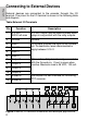
Figure: External I/O terminal schematics and example applications.
Table:External I/O Terminals
Pin Function Description
1 3.3 VDC
@200 mA max
3.3 VDC output. May be used to power small
relays in conjunction with the relay outputs.
2 Ground Ground.
3 Input 1 To activate, connect the Input to the Ground
pin. To deactivate, leave disconnected or
apply between 3-15 V.
4 Input 2
5 Input 3
6 Input 4
7 Output 1 When active, Output is internally connected
with the Ground pin. Circuit is open when
inactive. Maximum load is 25 VDC, 120 mA.
8 Output 2
9 Output 3
10 Output 4
11 RS485 A Half-duplex RS-485 interface for controlling
PTZ cameras.
12 RS485 B
GND
3.3V3.3V3.3V3.3V
GND3.3V
123456 7891011 12
RS485 Device