
User`s manual


E-10
A Check of the Supplied Items and the Names of the Parts
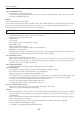
Names and Functions of the Parts (Projector)
Remotecontrol
IR sensor
Lenscap
Focusadjustmentring
Turn this to adjust the focus.
See Page E-24.
Projectionlens
The image is projected
from here.
* Be sure to remove the
lens cap before pro-
jecting.
Zoomlever
Turn this to adjust the screen size.
See Page E-24.
Documentcover
The document or printed material to be read is
placed under this cover.
See Page E-33.
Operationpanel
The buttons used for regular
operation are located here. See
Page E-13.
Tiltfoot
This foot is used to adjust the vertical angle of the
projection as well as the left-right balance. Turn-
ing it to the left extends it and turning it to the right
shortens it. See Page E-24.
Exhaustvents
Air is discharged from here.
Lampunitcover
(Underneathprojector)
The projection lamp unit is located inside.
See Page E-46.
ON/STANDBY
LAMP/COVER
TEMP
FREEZE OFF
FREEZE
PORTRAIT
INPUT
Airintake
Air is drawn in from the side.
Inputconnectorpanel
Included are connectors for per-
sonal computer, video, and USB
memory*, etc.
* Only for iP-01UE.
Tiltadjustmentlever
Press here to adjust the tilt foot. See Page E-24.
CAUTION
• Duringunitoperation,donotobstructthefrontofthelens.Duringoperation,stronglightthroughthe
lens is projected. Obstruct the front of the lens causes re or burn.
• Duringprojection,besuretoremovethelenscap.Negligencetoobserveitmaydeformthelenscap.
• Whenalampexplodes,itispossiblethatparticlesofglassandothermaterialmaybereleasedoutside
from the ventilation slots; therefore, do not bring your face close to the ventilation slots, or the air intake.