
Owner manual


Choose I/O Settings
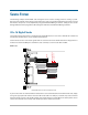
When programming a 6416Y2 card manually using its on‑board DIP switches, use switch block SW9 to set the
range of Slots (in blocks of 16 channels) that each 6416Y2 card will use when transmitting/receiving audio.
When programming the card using Pro64 Network Manager, these DIP switch settings are ignored.
DIP switches #7 and #8 are used for the receive Slot range, in groups of 16 channels (1‑16, 17‑32, 33‑48, or
49‑64). These are the channels from the Pro64 network being brought into the Yamaha device for mixing,
processing, etc.
DIP switches #5 and #6 are used to select the network transmit Slot range (available settings are 1‑16, 17‑32, 33‑
48, or 49‑64). Use these for audio being sent from the Yamaha device into the Pro64 network. Each Slot can be
activated individually using SW1 and SW2 (see below).
ON
ON
ON
ON
ON
ON
SW7
SW8
SW3
SW9
SW4
SW1
SW2
1 2 3 4 5 6 7 8 9 10
1 2 3 4 5 6 7 8 9 10
1 2 3 4 5 6 7 8
1 2 3 4 5 6 7 8
1 2 3 4 5 6 7 8
1 2 3 4 5 6 7 8
49-56 ON
57-64 ON
Receive 1-16
Transmit 49-64
MY16
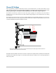
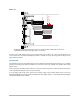
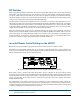
When programmed manually, block SW9 is used to choose A-Net Slot transmit (Tx) and receive (Rx) settings. The 6416Y2 card shown here
receives Slots 1-16 and transmits Slots 49-64 into the network.
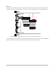
Remember that the 6416Y2 card functions as both an input and an output module. Set different Pro64 network
transmit/receive (Tx/Rx) Slot ranges to avoid channel/Slot allocation conflicts. This is especially important in
multi‑card systems.
41
co n f I G u r I n G t h e 6416Y2 ca r d