
Owner manual


Card 3 of 3
ON
ON
ON
ON
ON
ON
SW7
SW8
SW3
SW9
SW4
SW1
SW2
1 2 3 4 5 6 7 8 9 10
1 2 3 4 5 6 7 8 9 10
1 2 3 4 5 6 7 8
1 2 3 4 5 6 7 8
1 2 3 4 5 6 7 8
1 2 3 4 5 6 7 8
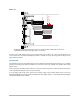
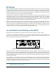
49-56 OFF
57-64 OFF
Receive 33-48
Transmit 49-64
MY16
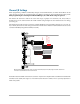
The third 6416Y2 card in the 48 x 16 digital snake receives Slots 33-48 from the network. As with card #2, none of its Slots are
transmitted back into the network even though the range is set to Slots 49-64.
As with card #2 of this digital snake, since the Transmit Slot range in SW9 is set to Slot range 49‑64 but has no
active channels (as seen in SW1 and SW2) this parameter could be set to any other range with no impact on the
digital snake’s operation.
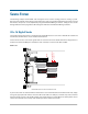
Install the Cards
Install 6416Y2 card #1 into Yamaha MY expansion slot #1, 6416Y2 card #2 into MY expansion slot #2, etc., to simplify
patching and routing from within the Yamaha user interface. Connect the 6416Y2 cards together with Cat‑5e
jumper cables.
If you are using the ASI A‑Net Systems Interface to connect a monitoring system, connect the monitoring devices
to the outputs marked 49‑64 on the rear panel of the ASI.
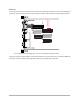
To create digital splits of the source signals in the network, simply connect Pro64 output devices such as the
6416o Output Module for analog outputs, the 6416dio for AES3 digital outputs, or even additional Yamaha digital
consoles with 6416Y2 cards installed.
45
co n f I G u r I n G t h e 6416Y2 ca r d