AN-16 A-Net Input Module User Guide P/N 9310 1007 0001 rev 2.00 © 2009 Aviom, Inc.
Certifications ETL/cETL Listed EMC: EN 55013, EN 55020, SAA AS/NZS 1053 Conforms to: IEC 60065, EN 60065, UL 6500-2001 Certified to: CAN/CSA E60065, KETI RoHS Status: Pb-free Pb Pb-Free Notice of Rights All rights reserved. No part of this document may be reproduced or transmitted in any form or by any means—electronic, mechanical, photocopy, recording, or otherwise—without written permission of Aviom, Inc.
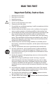
READ THIS FIRST Important Safety Instructions ! 1. 2. 3. 4. 5. 6. 7. 8. 9. 10. 11. 12. 13. 14. 15. 16. 17. Read these instructions. Keep these instructions Heed all warnings. Follow all instructions. Do not use this apparatus near water. Clean only with a dry cloth. Do not block any ventilation openings. Install in accordance with the manufacturer’s instructions.
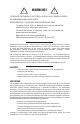
! WARNING! ! TO REDUCE THE DANGER OF ELECTRICAL SHOCK DO NOT REMOVE COVERS. NO USER SERVICEABLE PARTS INSIDE REFER SERVICING TO QUALIFIED SERVICE PERSONNEL ONLY To reduce the risk of fire or electrical shock, do not expose this product to rain or other types of moisture. To avoid the hazard of electrical shock, do not handle the power cord with wet hands. Replace fuse with same type and rating. Operating Temperature: 10˚C to 50˚C (50˚F to 122˚F) Risque de choc électrique – ne pas ouvrir.
Aviom, Inc. Limited Warranty Aviom, Inc. warrants this product against defects in materials and workmanship for a period of one year from the date of the original retail purchase. This warranty does not apply if the equipment has been damaged due to misuse, abuse, accident, or problems with electrical power. The warranty also does not apply if the product has been modified in any way, or if the product serial number has been damaged, modified, or removed.
Warranty Information Please record the following information for future reference: Your Authorized Aviom Dealer: Name: Address: Phone: Serial Numbers of Your Aviom Products: Date of Purchase: Your Authorized Aviom Dealer is your primary source for service and support. The information recorded above will be helpful in communicating with your Authorized Aviom Dealer should you need to contact Aviom Customer Service.
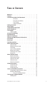
Table of Contents Welcome ��������������������������������������������������������������������������������������������������������1 Features ��������������������������������������������������������������������������������������������������������1 Conventions Used in this Document ������������������������������������������������1 AN-Series �������������������������������������������������������������������������������� 1 Using Personal Mixers �������������������������������������������������������� 2 Cat
Adding Personal Mixers ������������������������������������������������������������������ 24 Extending A-Net Cable Runs ����������������������������������������������������������������25 Audio Networks �����������������������������������������������������������������������������������������26 16-Channel Systems ��������������������������������������������������������������������������������26 32-Channel Systems ��������������������������������������������������������������������������������27 A-Net Expans
Welcome Thank you for purchasing the AN-16/i-M Mic Input Module, designed for use with the Pro16® Monitor Mixing System and audio networking products. All Pro16 products are powered by A-Net®, Aviom’s proprietary data transmission protocol designed especially for the unique demands of live streaming audio. This User Guide is designed to familiarize you with your new product and to have your system up and running in no time.
Using Personal Mixers It is possible to create an audio distribution and personal monitor system using any combination of Aviom AN-Series and Personal Mixer products, including the A-16II, and A-16R. When referring to the use of the personal mixers in a system in general, the terms A-16II Mixer or Personal Mixer are used to describe a case where a standard A-16II Personal Mixer or a rack mounted A-16R Personal Mixer (with/ without the optional A-16CS Control Surface) can be used.
Package Contents Check the contents of the shipping box carefully before making connections and continuing with installation.
Some of the benefits of using A-Net to transmit digital audio are: • • • • Virtually no latency No ground loops Easy cabling using readily available components An unlimited number of A-Net devices can be used in a system • Ease in spanning long distances between system components P Note: While the Cat-5e cables and connectors used on your Aviom products look like typical computer Ethernet network connections, do not connect computers, routers, or other home and business networking equipment to your Aviom p
The RJ45 connector looks similar to the connectors found on a telephone system, only larger. The twisting of the wire pairs helps to shield the cable from unwanted interference from electrical fields or radio interference (sometimes referred to as “RF”). Cat-5 cabling supports frequencies up to 100 MHz and speeds up to 1000 Mbps. RJ45 Jack Cat-5 Cable Cat-5 Cables The cables used with your Aviom system are interchangeable with any standard Cat-5e cables.
AN-16/i Input Module Up to 500 feet of Cat‑5e cable can be used to connect each system component AN-16/o Output Modules or Personal Mixers Infinite number of A-Net components Your cable length performance will be affected by a number of factors including the quality of the cables used, and the number of devices such as cable couplers used or passive wall panel interconnections in use. Use Cat-5e cable for best performance wherever possible. Stranded or solid Cat-5e cable can be used.
cable length specification can be compromised by using inline couplers or other passive connection devices. AC Line Conditioning Aviom products are digital devices and as such are sensitive to sudden spikes and drops in the AC line voltage. Changes in the line voltage from lightning, power outages, etc. can sometimes damage electronic equipment.
EtherCon Connector Some Aviom products use EtherCon® Cat-5 connectors. The Neutrik EtherCon connector is a dual RJ45 type connector. It can receive a standard Cat-5e cable or a cable fitted with the special heavy-duty EtherCon connector. When using a standard Cat-5e cable, plug the cable into the center of the jack; release the cable by pressing on the small plastic tab built into the cable connector. The locking EtherCon connector is similar to an XLR cable, the kind commonly used on microphones.
Front Panel Clip -10dB Signal Phantom Power +48V +48V 1 2 XLR: +6dB to +60dB TRS: -15dB to +36dB +6 +60 Gain +6 +60 Gain 85Hz 85Hz Flat Low Cut 1 2 Stereo Link Function 1 Clip LED 2 -10dB signal level LED 3 Signal present LED 4 +48 volt Phantom Power switch and LED 5 Rotary Gain knob 6 85Hz Low Cut rolloff 7 Phase Invert switch (polarity) 8 Stereo Link switch AN-16/i-M Mic Input Module User Guide 9
+48V +48V 15 16 AN-16 A-Net Input Module +6 +60 Gain +6 85Hz +60 Gain 85Hz 15 16 Power Stereo Link Function 9 Power LED 10 Power switch AN-16/i-M Mic Input Module User Guide 10
Rear Panel Input Mic/Line XLR Pin 2 Hot 15 16 14 13 12 14 13 12 Thru (DC Coupled Passive Splitter) 15 16 CAUTION Risk of electric shock! Do Not Open AVIS: Risque de choc electrique! Ne pas ouvrir 100-240VAC~ 50/60 Hz 60W CAUTION: Replace fuse with same type fuse and rating. 250VAC~ F4AL Send Send Send 16 15 14 Return Return Return WARNING! To reduce the risk of fire or electric shock do not expose this product to rain or moisture.
4 3 2 1 Conceived, designed and manufactured by Aviom, Inc.
Panel Descriptions This section explains the basic layout of your new Aviom product. The diagrams on the previous pages can be used as a quick visual guide to the location of the components of the AN-16/i-M mentioned in this section.
present, one LED to display when signal levels reach a point that is 10dB from maximum level, and another used to indicate that the input to a channel is causing audio clipping. The lower LED, marked Signal, will light as long as an audio signal of at least -40dB is present on the channel. It provides an easy way to confirm that audio is indeed passing into—and being processed by—the AN-16/i-M. The center LED lights when audio signals reach a level that is within 10dB of the maximum level before clipping.
Phantom Power +48V +48V 1 2 XLR: +6dB to +60dB TRS: -15dB to +36dB +6 +60 Gain +6 85Hz +60 Gain 85Hz Flat Low Cut 1 2 Stereo Link The channel gain, filter, and phase invert section of the channel strip Phase Invert Switch The Phase Invert switch alters the polarity of the audio signal on a perchannel basis. It can be used to correct phase anomalies that sometimes occur when using multiple microphones on the same sound source (such as a drum kit).
The default setting, with the Stereo Link switch to the left, allows independent control of each input channel from A-Net Personal Mixer products connected to the system. To link channels together as a stereo input, move the Stereo Link switch to the right. (Moving the switch to the link position causes all Personal Mixers connected to the system (including the A-16CS Control Surface used with the A-16R) to instantly update their channel status.
AN-16/i-M Rear Panel On the rear of the AN-16/i-M Mic Input Module are the power connector (with fuse), A-Net connections, the sixteen mic/line balanced analog audio inputs, the sixteen audio Thru jacks, and the balanced insert Send/Return jacks. Signal routing into and out of the AN-16/i-M Mic Input Module has been designed to be extremely flexible, allowing the AN-16/i-M to integrate into virtually any audio environment.
Channel Input Jacks The rear panel of the AN-16/i-M Mic Input Module contains sixteen audio input jacks. Microphones or line-level audio signals can be used. The combo jack used for audio input can accept an XLR connector or a ¼-inch TRS connector. The XLR input is designed to accept microphone-level signals from dynamic or condenser microphones. Phantom power (+48V) is supplied for each channel for use with condenser mics. The XLR input can also accept a line-level audio signal.
Channel Thru Jacks The sixteen XLR balanced audio Thru jacks on the AN-16/i-M provide an exact copy of the mic signal plugged into the Input jack just above it. This provides a passive splitter that can send a copy of the audio inputs to an analog audio mixer used for monitors in a digital snake installation, for example. No front-panel adjustments are passed on to the Thru connector with the exception of the phantom power used by condenser mics.
A-Net Connections Three A-Net connections appear on the rear panel of the AN-16/i-M Input Module. There are two A-Net Out jacks and one A-Net Expansion jack. 4 3 2 1 Conceived, designed and manufactured by Aviom, Inc.
meters), including connections using System Bridges. When a proper A-Net connection between the AN-16/i-M Mic Input Module and an AN-16/o Output Module (or Pro16 Series Personal Mixer) exists, the A-Net Active LED on the receiving device will light. A-Net Expansion The A-Net Expansion jack is used when creating a 32-channel digital snake or audio network using at least two AN-16/i-M Mic Input Modules and two AN-16/o Output Modules or other compatible output devices.
Parallel A-Net Routing Connecting A-Net devices in parallel involves the addition of an A-Net distributor. Any number of A-Net distributors can be added, creating an infinite number of digital splits. Using an A-Net Distributor AN-16/o AN-16/o AN-16/o A-16R A-16II A-Net In A-Net Out A-Net Distributor A-Net In A variety of A-Net compatible components are shown connected in parallel to an A-16D or A-16D Pro A-Net Distributor.
Connecting an Output Module To convert the mic- or line-level signals connected to the AN-16/i-M back to 16 discrete channels of analog audio, the AN-16/i-M needs to be connected to a compatible A-Net output module such as the AN-16/o Output Module. Simply connect a Cat-5e cable from A-Net Out on the AN-16/i-M to A-Net In on the output module. 16 Channels In AN-16/i-M AN-16/o 16 Channels Out A-Net Sixteen mic/line sources are output as analog audio up to 500 feet away.
To create a sixteen channel digital snake with splits: • Connect mic/line audio sources to the inputs of the AN-16/i-M • Connect the A-Net Out jack on the AN-16/i-M to the A-Net In jack on the first AN-16/o Output Module. • Expand the system by connecting a Cat-5e cable from the A-Net Out of the first AN-16/o Output Module to the A-Net In jack on the next AN-16/o Output Module • Repeat this same patching as needed for each additional AN-16/o added to the system. • Connect the audio outputs of each AN-16/o.
Extending A-Net Cable Runs To go longer than the maximum specified distance A-Net allows (500 feet, 150 meters), the A-16D (or A-16D Pro) A-Net Distributor can be used as a signal repeater. Simply insert the A-16D or A-16D Pro into the A-Net stream at the 500-foot point and the A-Net signal will be refreshed. Another 500 feet/150 meters of cable can be added. This process can be repeated as many times as required to extend cables.
Audio Networks Pro16 A-Net input and output modules can be combined to create digital snakes and audio networks of up to sixty-four audio channels with unlimited expansion. When more than sixteen channels of audio are required in a Pro16 system, there are several options available. Systems using sixteen or thirty-two audio channels can be configured with no additional hardware using the built in A-Net Expansion port.
32-Channel Systems Aviom’s Pro16 Series of audio network products work in groups of sixteen channels. Audio networks of thirty-two channels can be configured as: • 32 channels send by zero channels return (32 x 0 ) • 16 channels send by 16 channels return (16 x 16) • 0 channels send by 32 channels return (0 x 32) The descriptions above are similar to those used for traditional analog audio snakes. The configurations refer to the number of audio channels used as inputs on each side of the snake.
Some points to remember about using the A-Net Expansion jacks on the Pro16 input modules and AN-16/o to create a digital snake or audio network: • When creating a network with four Pro16 Series units, one A-Net Expansion jack will be connected to an A-Net In port while the other A-Net Expansion jack will be connected to an A-Net Out port. • The A-Net Out jacks on the AN-16/o Output Modules should be empty when only four Pro16 Series units are being used to create a network.
32-Channel Snake The 32 x 0 configuration has all audio inputs on one side of the system and all audio outputs on the other side. This setup could be used to send 32 mic signals form a stage to a front-of-house (FOH) mixing console, for example. Audio channels 1-16 16 Channels In AN-16/o AN-16/i-M 16 Channels Out A-Net Expansion 16 Channels In AN-16/i-M Audio channels 17-32 AN-16/o 16 Channels Out A-Net 32 channels are sent from a stage to the FOH mix position.
Front-of-house Stage Channels 1-16 Channels 17-32 Cat-5 connections for a 32 x 0 system, shown in a live performance setting; use either AN-16/i or AN-16/i-M Input Modules as needed. 16 Channels Send by 16 Channels Return The 16 x 16 configuration has sixteen inputs and sixteen outputs on each side of the digital snake or audio network.
Front-of-house Stage Channels 1-16 Channels 17-32 Cabling for a 16 x 16 system; use either AN-16/i or AN-16/i-M Input Modules as needed. To configure a 16 x 16 system: 1. Set up one Pro16 input module (AN-16/i or AN-16/i-M) and one AN-16/o on each side of the network. (For example, one set is at the front-of-house mix position, the matching set is placed on the stage.) 2. Connect sixteen mic- or line-level audio sources to inputs 1-16 on the first Pro16 input module. 3.
Adding More Audio Outputs As mentioned previously, the A-Net Out jacks on the AN-16/o Output Modules remain available even when creating a bidirectional digital snake or audio network. This allows additional output modules to be added as needed to create digital splits for a variety of audio situations. Any Pro16 Series A-Net compatible product can be added to an A-Net Out port.
an AN-16/o Output Module that you want to use to expand the system. • Each additional AN-16/o that you want to add is connected by patching a Cat-5e cable from the A-Net Out jack on the module preceding it to its A-Net In jack. Using an A-Net Distributor While the A-16D and A-16D Pro Distributors are not compatible with the data being generated by the A-Net Expansion ports on the AN-16/i, AN-16/i-M and AN-16/o, you can use a distributor to add wiring flexibility to your system.
64-Channel Systems When used with the optional AN-16SBR System Bridge, Pro16 input and output modules can create digital snakes of up to sixty-four channels. Up to four input modules and four output modules can be used in a variety of combinations to create a flexible and reconfigurable audio distribution network. Console cards can also be used as input modules.
Connecting the System Bridge Adding a System Bridge to a system is quite simple. Two System Bridges are used to create a network The four A-Net connectors (labeled A, B, C, and D) on the one side of the network are directly related to the A, B, C, and D connectors on the other side of the network. That is, if you patch an AN-16/i Input Module into port “A” on one side of a System Bridge, an AN-16/o Output Module would be connected to port “A” on the other side of the System Bridge.
4. 5. Repeat this process to connect ports B, C, and D to the remaining AN-16/o Output Modules. Connect the two sides of the audio network by running a Cat-5e cable (with or without an EtherCon connector) between the Bridge jacks on the System Bridges. To use other configurations, simply move any pair of input and output modules. In the following example, the devices connected to port D on the AN-16SBR System Bridge have been swapped to create a 48-channel send x 16-channel return system.
A-Net Out AN-16/i-M AN-16/i-M AN-16/i-M AN-16/o A B Bridge C D System Bridge A B C D System Bridge A-Net In AN-16/o AN-16/o AN-16/o AN-16/i-M Ports A, B, and C use the same type of module. A-Net Out AN-16/o AN-16/i-M AN-16/i-M AN-16/i-M A B B r id ge C D System Bridge A B C D System Bridge A-Net In AN-16/i-M AN-16/o AN-16/o AN-16/o Ports B, C, and D use the same type of module. For a 32 x 32 configuration, place two similar modules together, connected to ports B, and C on the System Bridge.
the A-16D Pro) can also be used to expand a system. The following example shows one variation of an expanded system. B r i d ge A B C D System Bridge A-Net In A-Net Out AN-16/o AN-16/o AN-16/o AN-16/o AN-16/o AN-16/o AN-16/o AN-16/o A-16D A-16R A-16R A-16R A-16R A-16R AN-16/o One side of an expanded digital snake system This example starts as a 64 x 0 configuration (the input side of the system is not shown in the diagram). Two of the outputs are expanded.
System Bridges can also be used to combine A-Net streams from multiple networks in an installation, allowing, for example, ports A and B from Network #1 to be sent along with streams B and C from Network #2 to a third area, creating Network #3.
A-Net Out AN-16/o AN-16/i-M AN-16/i-M AN-16/o A B Bridge C D System Bridge A B C D System Bridge A-Net Out AN-16/o AN-16/i-M AN-16/i-M AN-16/o A B Bridge A B C D C D System Bridge System Bridge Bridge A-Net In AN-16/i-M AN-16/o AN-16/o AN-16/i-M A-Net In AN-16/i-M AN-16/o AN-16/o AN-16/i-M A B C D System Bridge A-Net Out A B C D System Bridge A-Net In AN-16/o AN-16/o AN-16/o AN-16/o An expanded digital snake using two System Bridges The output modules connected to ports B and C from the
Specifications XLR Input (mic/line) Pin 1: Ground; Pin 2: Audio +; Pin 3: Audio - TRS Inputs (balanced line level) Tip: Audio +; Ring: Audio -; Sleeve: Ground Insert Send and Return Tip: Audio +; Ring: Audio -; Sleeve: Ground Audio Thru (XLR) Pin 1: Ground; Pin 2: Audio +; Pin 3: Audio Direct coupled passive throughput Operating Level +4dBu Insert Send Connector: TRS Signal: Impedance Balanced Nominal level: 0dBu Peak Level (A/D clip point): +14dBu The Send connector is a line output in the sign
Signal to Noise Ratio (unweighted) Send jack: -113dB (Gain = minimum) Mic Input EIN (Equivalent Input Noise): -128dBu A/D: -105dB Reference = +14dBu (A/D clip point) (Rs = 150 Ohms, 20kHz BW, Gain = +60dB) CMMR (Common Mode Rejection Ratio): 80dB @ 120Hz (Gain = +60dB) Low Cut Filter -3dB @ 85Hz, -18 dB per octave Phantom Power +48 Volts, per channel Splitter Output, Mic Thru Direct coupled passive throughput A/D converters 24 bit Digital Outputs A-Net: 2 (Main and Aux) A-Net Expansion: 1 RJ45
Block Diagram AN-16/i-M Mic Input Module User Guide Audio thru 1-16 Mic: + 6dB to +60dB Line: -15dB to +36dB Gain Insert in XLR/TRS Audio Input 1-16 +48V Phantom Insert out HPF Insert Insert point A/D converter Stereo Channel Link A-Net Signal -10dB Clip This block diagram shows the signal path as it flows through the AN-16/i-M.
Dimensions AN-16/i-M Mic Input Module User Guide 44
AN-16/i-M Mic Input Module User Guide 45
Index Symbols -10dB LED 9 16-Channel Systems 26 32-Channel Systems 21, 27 +48 volt 9, 11, 14 64-Channel Systems 34, 36 85Hz Low Cut 9 85Hz Low Cut rolloff 14 A A-16CS Control Surface 16 A-16D 2 A-16D A-Net Distributor 3 A-16D Distributor 21, 25, 28, 33, 38 A-16D Pro 2 A-16D Pro A-Net Distributor 3 A-16D Pro Distributor 21, 33 A-16II 24 A-16II Personal Mixer 16 A-16R 16, 24, 33, 38 AC current 17 AC Line Conditioning 7 A/D converter 42 Adding More Audio Outputs 23, 32 Adding Personal Mixers 24, 32 AN-16/i In
L Control Surface 16 crossover cables 5 D daisy-chain 21, 24, 38 digital snake 15–25, 26 digital split 22, 23, 32 digital splits 26 Direct Line Outputs 19 Distributor 22, 33, 38 E effects device outputs 15 EtherCon Connector 36 Ethernet 3 expanded network 32 Expanding 33, 37 Expansion 12, 21, 28, 29, 34 Expansion jack 34 Extending A-Net 25 F fiber optic 25 FOH 26 Frequency Response Front Panel AN-16/i 13 Fuse 11, 42 41 G Gain 9 Gain knob 14, 18 Gain Range 14, 41 Group A-16II and A-16R 16 guitar 18 I
Personal Mixers 32 Phantom Power 14, 19, 42 phantom power switch 9 Phase Invert Switch 9, 11, 15 polarity 9 ports 35 Power Connector 17 Power LED 10, 16 Power Supply 17, 42 Power switch 10 Pro16 1, 3, 24 Pro16 Monitor Mixing System 3, 24, 32 Pro16 Personal Mixer 15 Pro16 Series 27, 32 Pro64 4 R Rear Panel description repeater 25 Return insert 19 Insert 41 Return jack 12 RJ45 8 RJ45 connector 5 RoHS ii Rolloff 9, 14 router 4 rumble filter 14 17 T Thru jack 11, 19 Tip, Ring, and Sleeve 18 TRS 18, 19, 41 TR
Warranty Registration Please take a moment to fill in this warranty registration form. Return it to Aviom via mail or fax. All information will be kept confidential.
1157 Phoenixville Pike, Suite 201 • West Chester, PA 19380 Voice: +1 610.738.9005 • Fax: +1 610.738.9950 • www.Aviom.