DMP-300 Digital Media Player Installation Guide Version: V3.0 Date: 08 September 2009 Doc Number: DMP010 AVIONICS INNOVATIONS, INC. 2450 Montecito Road Ramona, CA 92065 Phone (760) 788-2602 Fax (760) 789-7098 www.avionicsinnovations.
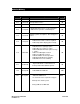
Revision History Version Date Description By V1.0 05-Jan-02 Initial Release SB V1.1 10-Jun-02 First production release SB V1.2 30-Jul-02 Added GPS Monitor screen SB V1.3 11-Sep-02 -Clarified pull-down resistors for discrete triggers. -Added remote operations of PAUSE input. SB V1.4 14-Jan-03 Added Jog Mode description to discrete triggers 6 and 7 SB V1.
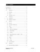
Table of Contents Revision History ..................................................................................................2 Table of Contents................................................................................................3 1.0 Introduction ......................................................................................5 1.1 Description .......................................................................................5 1.2 Scope .....................................
.1.1 Discrete Triggers 1 Through 7 – Active Level..........................12 4.1.2 External Pause – Active Level ..................................................12 4.1.3 External Chime Length..............................................................12 4.1.4 Display Brightness.....................................................................12 4.1.5 MINIMUM External Dimmer Level............................................13 4.1.6 MAXIMUM External Dimmer Level ...........................
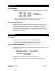
1.0 Introduction 1.1 Description The DMP-300 Digital Media Player is a self-contained unit which stores and replays prerecorded audio tracks. The audio tracks are encoded in “Motion Picture Expert Group (MPEG) Level 3” format, commonly referred to as “MP3”. Audio files are stored in a removable Compact Flash™ memory card which is prepared and installed by the user. Audio tracks are selected via a single rotary pushbutton on the front panel of the DMP-300.
2.0 Mechanical 2.1 Specifications The DMP-300 is fully contained within a 2-inch (5cm) high standard DZUS mount enclosure. Height: Width: Depth*: Weight: 2.0 in. 5.75 in. 5.0 in. 3.25 in. 0.75 lb (5.1 cm) (14.6 cm) (12.7 cm) (8.26 cm) (350 g) Front Panel System Enclosure * Connector shell protrudes 0.25” (0.64 cm) beyond system enclosure. Allow an additional 2.5” (6.35 cm) behind unit for mating connector and wiring. 2.
3.3 3.3.1 Inputs Dimmer The vacuum-fluorescent display on the DMP-300 can be set to one of eight different levels of brightness in Setup Mode. Alternatively, the brightness level may be selected via the external dimmer input. Three different inputs are provided for each of the three common types of dimmer busses: 05VDC, 0-14VDC and 0-28VDC. Connect the aircraft dimmer signal to only one of these inputs. The two remaining unused inputs must remain unconnected.
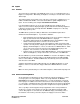
after each track to initiate playback of the next audio track. The Remote Pause/Play input can be configured in Setup Mode as active high or active low. It can also be configured as either an “edge-activated” or a “level-activated” signal: • Edge-Activated When set to “edge-activated” (the default setting), the remote pushbutton works exactly like the front panel knob.
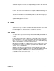
Example: Active Low Example: Active High 3.3.4 Jog Mode If enabled on the memory card using the CardPrep software, Jog Mode causes four of the available seven trigger inputs to be redefined: - Triggers 6 and 7 are used to remotely step the DMP-300 through its menus. This is particularly useful for helicopter installations or any installation where the pilot needs to be able to quickly step back or ahead through the playlists and select a new track.
configured to illuminate whenever the corresponding audio track is playing. This configuration is selected in Setup mode. See the Setup description on page 15. 3.3.6 GPS Data The DMP-300 can receive RS-232 or RS-422/485 serial data from panel-mount GPS receivers. This feature allows an audio track to be assigned to a latitude/longitude trigger via the CardPrep software. The GPSIN pin should be connected to either the GPS receiver’s RS232 out pin, or to RS-422 “Data HI” or RS-485 “Data B”.
3.
4.0 Setup Mode 4.1 Entering and Exiting Setup Mode Setup Mode is entered via the following steps: 1. Turn the unit off by pulling on the on/off knob 2. Depress and hold the front panel rotary knob. 3. Apply power by pushing in the on/off knob while continuing to hold in the front panel rotary knob. 4. Release the rotary knob when the display first lights up. After the 5-second intro screen, the first Setup Mode item is displayed. Setup Mode is exited by simply turning off the unit.
4.1.5 MINIMUM External Dimmer Level If is selected as the display brightness, the DMP-300 will automatically choose one of eight levels of brightness depending on the external dimmer input control voltage. This Setup option allows you to set the value of external dimmer input corresponding to the lowest brightness of panel lighting. The DMP-300 will use the spread between this value and the MAX level, and will choose one of eight brightness levels accordingly.
helpful suggestions of user interface options. Each push of the front panel knob toggles between the selections of each type of display. 4.1.9 GPS Status To aid with installation troubleshooting, this screen presents a continuously-updated message describing the state of the GPS data input. One of three messages will be displayed: Message Description no GPS RS232 No serial GPS data is being received at all. Check power and wiring.
4.1.12 Dedicated Annunciators for Triggers 1, 2 and 3 This page allows the selection or deselection of “Dedicated Annunciator Mode” for Triggers 1, 2 and 3. When enabled, this mode causes a separate discrete annunciator to illuminate whenever the audio track for that trigger is playing. A particular installation could include up to three dedicated pushbuttons for (particular briefing tracks, background music, etc) along with an annunciator to indicate when that trigger is active.
1. Press and hold the rotary knob while pushing in the on/off knob turning on power. Release the button when the DMP-300 display first lights up. 2. The DMP-300 will be in SETUP mode. Advance through all the setup items as described above, and set the options to match your installation. Do NOT select the setup item: “Set LOUD volume level” unless you have a memory card installed that has been prepared using the supplied CardPrep software. 3.
6.0 Troubleshooting and Error Messages 6.1 Troubleshooting Here are a few common problems and their potential causes: Symptom No audio, even though display shows track playing. Possible Causes/Solutions • Not using a Sandisk card may be a possible cause of failure. Only Sandisk brand cards should be used in the DMP-300 • Volume turned down. Last volume setting is retained between power cycles, and previous user may have turned volume way down. Push-and-turn knob to change volume.
6.2 Error Messages In addition, the DMP-300 may display the following error messages: Display Meaning Invalid Card, no firmware. The firmware update file, “0002.hex”, cannot be opened on the CompactFlash card. Invalid Card, no MP3 config. The MP3 configuration file, “0002.xd3”, cannot be opened on the CompactFlash card. Internal error number XX A fault has occurred between the two internal processors of the DMP-300.
7.0 Drawings 7.1 Mechanical Drawing DMP-300 INSTALLATION GUIDE P/N DMP010 V3.
7.2 Electrical Interconnect DMP-300 INSTALLATION GUIDE P/N DMP010 V3.