
Installation guide


DMP-300 INSTALLATION GUIDE PAGE 6 OF 20
P/N DMP010 V3.0
2.0 Mechanical
2.1 Specifications
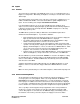
The DMP-300 is fully contained within a 2-inch (5cm) high standard DZUS mount enclosure.
Height: 2.0 in. (5.1 cm)
Width: 5.75 in. (14.6 cm) Front Panel
5.0 in. (12.7 cm) System Enclosure
Depth*: 3.25 in. (8.26 cm)
Weight: 0.75 lb (350 g)
* Connector shell protrudes 0.25” (0.64 cm) beyond system enclosure. Allow an
additional 2.5” (6.35 cm) behind unit for mating connector and wiring.
2.2 Mounting Considerations
The DMP-300 should be installed in a normally heated, pressurized section of the aircraft,
however the unit contains no moving parts and does not require special vibration isolation.
The unit may be mounted in an auxiliary area of the instrument panel, in a pedestal, or
anywhere in the aircraft cabin outside of the cockpit. In a severe vibration environment, the
unit should not be mounted vertically with the front panel facing down, to ensure that the
memory card does not accidentally vibrate loose. Otherwise, the DMP-300 may be installed in
any orientation and at any angle.
3.0 Electrical
3.1 General
The following guidelines should be used when installing the DMP-300:
♦ All wiring to be installed in accordance with FAA AC-4313-1A, Chapter 11, Sect. 2
♦ All non-audio wiring to be MIL-W-22759 unless otherwise specified
♦ All audio wiring to be MIL-C-27500 shielded unless otherwise specified
3.2 Connection to Aircraft Power
The DMP-300 accepts a wide range of input voltage directly, without the need for converters or
configuration changes.
Minimum input: 10.0 VDC (1.0 Amp @ 10.0 VDC)
Maximum input: 35.0 VDC (0.1 Amp @ 35 VDC)
Nominal input: 14 VDC / 0.5 Amp
28 VDC / 0.25 Amp
Aircraft power must be supplied via a 2 Amp resettable circuit breaker.
The DMP-300 has a switch mounted on the face of the unit labeled “push on” “pull off”.