Instruction Manual For intermediate to advanced pilots
SAFETY INSTRUCTIONS 1. Please read this manual carefully and follow the instructions before you use this product. 2. This airplane is not a toy, due to it's advanced flying qualities it is only suitable for experienced pilots. If you are a novice then please only operate with the assistance of an experienced pilot. 3. Not recommended for children under 14 years old. 4.
The C-130 is an American four-engine turboprop military transport aircraft which is capable of using unprepared runways for takeoffs and landings. The C-130 was originally designed as a troop, medevac, and cargo transport aircraft. The versatile airframe has found uses in a variety of other roles, including as a gunship (AC-130), for airborne assault, search and rescue, scientific research support, weather reconnaissance, aerial refueling, maritime patrol and aerial firefighting.
Assembly 1 Main fuselage assembly. 2 Install the fiberglass rods into the carbon sleeves at the rear of the fuselage as shown.
4 Slide the tail assembly onto the rods 5 6 4
7 Then install the vertlcal fin onto the fuselage. 8 9 3mm x 25mm 3mm x 20mm Use the supplied screws to lock the vertical fin onto the fuselage. Note: The longer 3x25mm screw should be installed just behind the cargo bay door as shown in the picture above.
10 Install the supplied rudder steering control horn as shown in the picture. (Z link goes to the servo horn). 11 Ensure the rudder control surface is aligned with the vertical fin. Use an Allen key to tighten the grub screws of the control horn and also apply some Loctite glue onto the threads. The rudder servo horn and the rudder control horn should be at 90° to the main axis of the fuselage.
12 Slide into the fuselage the main wing spar. 13 Install both wings.
15 Push both wings up against the fuselage wing roots, make sure the electrical connectors on the wings line up and plug in correctly. 16 3mm x10mm Insert 4 off 3mm x 10mm screws into the fuselage wing roots as shown. Use a Hex key with ball end to tighten the screws.
17 18 Install the propeller assemblies as shown. Use a Hex key to lock the prop adaptor onto the motor shaft then fit the propeller and spinner. Note: Apply some Loctite to the threads and then tighten the screws securely.
19 Install the outboard flap pushrod linkages to the flaps as shown. (Z link to the servo horn). 20 Install the elevator pushrod linkage to the elevator as shown. (Z link to the servo horn).
Figure 1 Figure 2 Plug in the UBEC cables to the power cables on the plane. Pay attention to the polarity and ensure that all the pins are fully seated into the socket. See pic #1 and #2.
Radio Control Setup Please also study your computer radio instruction manual carefully for the programming and the proper setup of each function on this airplane. Flaps setting procedure: Note: Please do not have the flap control linkages attached until you have the radio set up done. Once you have set up your radio you may install the control linkages and fine tune the flap control surface travels evenly on both sets of flaps on both wings. 1.
12. Finally check again to ensure all the flap control surfaces are operating in the same manner. 13. Pic #3 below shows the inboard and outboard flaps when fully deployed. Pic #1 Pic #2 Pic #3 Cargo bay door setting procedure: 1. Switch on your radio. You can either assign a two way switch or a three way switch to a free channel to operate the cargo bay door. 2. Then go into the end points setup page. 3. Adjust both end points to approximately 30% of the total travel on either side. 4.
For a two way switch setup 1. Adjust the end point so that with the switch position selecting the door closed and the door is flushed with the fuselage and there is no buzzing from the servo. 2. Flick the switch to the door down position and adjust the end point so that the door just misses the ground. For a three way switch setup 1. Flick the switch to the door up position and adjust the end point value until it is flushed with the fuselage and there is no buzzing from the servo. 2.
Put the C-130 on a plane stand. 1. With landing wheels down ( gear switch should be in gear down position ). 2. Replace the depleted battery with a fresh battery pack and hook it up to the power input cables. 3. Cycle the gear switch once. 4. Only the nose gear door will open and close again ( Nose wheels and main wheels will remain in the down position ). 5. Flick the retract switch to the retracted position. It will operate normally with all the wheels retracting and all the doors closed.
Scale detail parts assembly: Pictures showing the fitting of the windshield wipers.
Fitting the pitot tubes.
18
Fitting the dew point sensor.
Note: The cargo door ramp is just only for you to install it when you want to display your Avios C-130 on the ground for the most ultimate scale looking model. Please don't install it and use it in flight whatsoever. Again, the ramp is for display purposes only.
Direction of propellers rotation CAUTION: Please stay away the spinning propellers at all times.
Accessories 1 3 2 4 5 6 7 8 Main Wing HM 3 mm x 10 mm Flap HM 2 mm x 10 mm Aileron HM 2 mm x 10 mm Elevator HM 2 mm x10 mm Scale detail parts UBEC 5V 3A Joiner spar for the empennage Rudder PM 3 mm x 20 mm PM 3 mm x 25 mm Cargo bay door ramp 1 Fuselage 4 Vertical tail 7 Wing joiner 2 Main wing 5 Propeller 8 3 Horizontal tail 6 Auxiliary tank Control linkages accessory parts, ubec and cargo bay door ramp 22
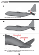
Recommended Control Throws 15mm 15mm Elevator travel: 15mm up / 15mm down Ailerons travel: 10-12mm up / 10-12mm down Rudder travel: 10-12mm left / 10-12mm right 12 mm Outboard flap travel: 12mm down 23 23 25
Specifications 1195 mm 6.5 x 5 inch 4-blade propeller x 4 pcs Brushless Outrunner Motor, 4S 2627 KV1000 1600 mm 18A Brushless ESC x 4 pcs Servos: 9 g x 14 pcs Battery: 2200 mAh 4S 14.8V 40C ( Recommended ) Radio System: 2.4 Ghz 8 Ch & up Transmitter and Receiver 2.
25
26
We reserve the right to change or modify the specification and the product design of this product without prior notice.