AviStart 3001 Installation Manual, Revision B 100199
Table of Contents Important Information . . . . . . . . . . . . . . . . . . . . . . . . . . . 1 Recommended Installation Tools . . . . . . . . . . . . . . . . . . . . 1 Recommended Procedures . . . . . . . . . . . . . . . . . . . . . . . 1 14 Pin Connector . . . . . . . . . . . . . . . . . . . . . . . . . . . . 3 6 Pin Connector . . . . . . . . . . . . . . . . . . . . . . . . . . . . . 3 Installation Procedures. . . . . . . . . . . . . . . . . . . . . . . . . . . 4 Control Unit . . . . . . . . . . . . . . .
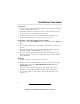
Important Information Recommended Installation Tools Voltmeter Wire Strippers Electrical Drill & Bits Phillips Screwdriver Convoluted Tubing * Solder Gun * Wire Crimpers Shrink Tube or Electrical Tape * Optional Recommended Procedures 1 . Test all circuits with a voltmeter. 2 . Make all wiring connections with the supplied solderless crimp connectors. DO NOT twist wires or use scotch-lok connectors. 3 . Route the small and large RED, RED/WHITE and BLACK wires from the control unit directly to the battery.
Main Wiring Diagram 2 AviStart 3001 Installation Manual, Revision B 100199
14 Pin Connector Pin Number Wire Color Description 1 2 3 4 5 BLUE/WHITE GREEN/WHITE ORANGE/BLACK WHITE/BLACK Lock (-) Output Unlock (-) Output Glow Plug Light (+) Input Dome Light (-) Output for Factory Alarm Rearming Battery (-) BLACK WHITE/GREEN YELLOW YELLOW/BLACK TAN RED/BLACK GRAY/BLACK GRAY/WHITE RED/WHITE RED 6 7 8 9 10 11 12 13 14 Tachometer Input Brake Switch (+) Input Reverse Light (+) Input Hood Switch (-) Input Parking Light Output Remote Start Activated (-) Output Factory Alarm Disarm (
Installation Procedures Control Unit 1 . Select a location under the dash that will allow you to use the tie wraps to securely fasten the control unit. 2 . Mount the control unit as high as possible to ensure maximum security. 3 . Do not mount the control unit near moving parts. 4 . Avoid areas that are in the direct path of air blowing from the vents. 5 . Route wires from this point, leaving slack for ease of service. RangeMaster™ Super Heterodyne Receiver Module 1 .
Valet Switch 1 . Discuss placement with the owner. 2. Choose a location for the valet switch that is hidden, but convenient for the owner to access. 3 . Drill a ¼" hole and mount the switch. 4. Route the valet switch wires to the control unit. 5 . Plug the valet switch WHITE connector into the control unit WHITE plug.
Reverse Light : Some vehicles allow you to remove the gear shift selector from "Park" even while the ignition key is not on. As a safety I CAUTION feature, the system will monitor the reverse wire. If the vehicle is removed from "Park" while in the remote start mode, the system will shut down immediately. 1 . Set the parking brake. 2 . Turn the ignition key to the "ON" position and adjust the gear shift selector to "Reverse." 3 .
System #1 This type of system has a designated alarm arm wire that requires a (-) pulse to arm the alarm 1. Use a volt/ohmmeter to find the factory arm wire that will show (-) ground while the driver door key cylinder is turned to the "LOCK" position. If you are interfacing with the vehicle power door locks, use the diagram at right. If not, proceed to step #2. 2. If you are not interfacing with the vehicle power door locks, connect the AviStart BLUE/WHITE wire to the vehicle arm wire.
Ignition #1 Ignition #2 The AviStart module has two onboard 30-amp relays. Most vehicles have only one ignition wire necessary to start the vehicle. Some vehicles have two ignition wires. Make all wire connections at the ignition switch wire harness. 1 . Use a voltmeter to locate the wire(s) that show +12 volts while the ignition key is in the "ON," "CRANK" and "RUN" positions and 0 volts when the ignition key is in the "OFF" position. 2 . Connect the 14 ga PINK wires to the vehicle ignition wire. 3.
Remote Engine Start Neutral Safety Switch Bulletin A neutral safety switch is a mechanism on almost every vehicle equipped with an automatic transmission. The neutral safety switch prevents the vehicle from starting while the gear shift selector is in "Reverse" or "Forward" gear positions. There are basically two types of neutral safety switches. The most common is the mechanical (separate) neutral safety switch. A small group of vehicles use a combined neutral safety switch.
NOTE: Use the following test procedure upon completion of every remote start regardless of the make and model of the vehicle. Test Procedure Be sure there is at least 5 feet of unobstructed clearance at the front and rear of the vehicle. Make sure to alert anyone near I CAUTION: the vehicle you are testing that the vehicle may move forward slightly. 1. Apply the parking brake. 2 . Turn the ignition key to the "ON" position and place the vehicle in "DRIVE." 3.
Gen eral Mo tors Sport Util ity Ve hi cles, Trucks and Col umn Shift Pas sen ger Ve hi cles Dodge Da kota Pickup Trucks 11 AviStart 3001 Installation Manual, Revision B 100199
Glow Plug Light Monitoring The glow plug light (+) input wire will monitor the glow plug light in the dashboard. When a remote start is attempted, the ignition will turn on and when the glow plug light turns "OFF" the engine will start 1 . Locate the glow plug light wire that will show (+) 12 volts while the ignition key is on and the glow plug light wire is illuminated. 2 . Connect the AviStart ORANGE/BLACK wire to the vehicle glow plug might wire.
13 AviStart 3001 Installation Manual, Revision B 100199
14 AviStart 3001 Installation Manual, Revision B 100199
Tach Wire (RPM Monitoring) The AviStart is designed to monitor the vehicle RPM by connecting directly to the vehicle tachometer wire which is usually located at the distributor, ignition coil or diagnostic plug. On most vehicles, the tach wire is easily accessible. If the tach wire is not accessible, there are several alternative choices. Contact Avital Technical Support Department for alternate choices.
Power and Ground Connections : Do not plug in the system fuses until the final step below. I CAUTION 1 . Connect the 18 ga RED wire to one end of a supplied 20 amp fuse assembly. 2. If the vehicle parking lights are positive trigger, connect the RED/WHITE wire to one end of the other supplied 20 amp fuse assembly. 3. Connect the BLACK wire to the 10 mm ring terminal. 4. Connect the 10 ga RED wire to one end of both 30-amp fuse assemblies. 5.
Programmable Features All AviStart system and remote control programmable features are accomplished by turning the ignition key to the “ON” position or starting the engine and flicking the valet switch on and off a preset number of times. The built-in piezo beeper will beep for audible programming confirmation. The AviStart also allows the user to add new remote controls in one step, delete lost or stolen remote controls or rearrange the factory preset remote control functions. 1 .
Programming Table for System Features Feature Factory Setting No.